1
®
MILLER
GyroMixer
Operation &
Instruction
Manual
Part No: 4708000
Rev. H
10.30.09
©2009 Fluid Management as published work all rights reserved.
Under the copyright laws, this material may not be copied, in whole or in part, without the
written consent of Fluid Management.
Your rights to the software are governed by the accompanying software license
agreement.
Use of Fluid Management trademarks, service marks, or logos for commercial purposes
without the prior written consent of Fluid Management may constitute trademark
infringement and unfair competition in violation of federal and state laws. Fluid
Management, FMDirect, ColorPro, DVX, Harbil, Blendorama, Accutinter, Duraflow, Fast &
Fluid Management, GyroFlex, GyroMixer, Infina, MicroTint, TintMaster, V1, and VR1 are
trademarks of Fluid Management, registered in the U.S. and/or other countries.
Every effort has been made to ensure that the information in this guide is accurate.
Fluid Management is not responsible for printing or clerical errors.
Fluid Management
1023 Wheeling Road
Wheeling, Illinois 60090-5776 USA
800-462-2466
http://www.fluidman.com
Published in the United States.
Mention of third-party products is for informational purposes only and constitutes neither
an endorsement nor a recommendation. Fluid Management assumes no responsibility
with regard to the performance or use of these products
Fluid Management Customer Service 1.800.462.2466
Table of Contents
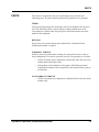
SAFETY INFORMATION . . . . . . . . . . . . . . . . . . . . . . . . . . . . . . . .1
MIXER WARNING LABELS . . . . . . . . . . . . . . . . . . . . . . . . . . . . . . . . 1
SAFETY NOTICE INFORMATION . . . . . . . . . . . . . . . . . . . . . . . . . . 1
WARNINGS AND CAUTIONS . . . . . . . . . . . . . . . . . . . . . . . . . . . . . . 2
INTRODUCTION . . . . . . . . . . . . . . . . . . . . . . . . . . . . . . . . . . . . . . .3
PRODUCT DESCRIPTION . . . . . . . . . . . . . . . . . . . . . . . . . . . . . . . . 3
SPECIFICATIONS . . . . . . . . . . . . . . . . . . . . . . . . . . . . . . . . . . . . . . . 3
CONTAINER DIMENSIONS . . . . . . . . . . . . . . . . . . . . . . . . . . . . . . . 3
ELECTRICAL SUPPLY . . . . . . . . . . . . . . . . . . . . . . . . . . . . . . . . . . . 4
EQUIPMENT MAINTENANCE LOG. . . . . . . . . . . . . . . . . . . . . . . . . . 5
SPARE PARTS ORDER FORM . . . . . . . . . . . . . . . . . . . . . . . . . . . . . 6
UNPACKING DIRECTIONS . . . . . . . . . . . . . . . . . . . . . . . . . . . . . .7
INSPECT FOR DAMAGE . . . . . . . . . . . . . . . . . . . . . . . . . . . . . . . . . 7
REMOVE MIXER FROM SKID . . . . . . . . . . . . . . . . . . . . . . . . . . . . . 7
UNPACK THE MIXER . . . . . . . . . . . . . . . . . . . . . . . . . . . . . . . . . . . . 7
SETTING UP THE MIXER . . . . . . . . . . . . . . . . . . . . . . . . . . . . . . .8
INSTALLATION . . . . . . . . . . . . . . . . . . . . . . . . . . . . . . . . . . . . . . . . . 8
ELECTRICAL CONNECTION . . . . . . . . . . . . . . . . . . . . . . . . . . . . . . 8
LEVELING . . . . . . . . . . . . . . . . . . . . . . . . . . . . . . . . . . . . . . . . . . . . 11
OPERATIONAL TEST . . . . . . . . . . . . . . . . . . . . . . . . . . . . . . . . . . . 12
OPERATIONS . . . . . . . . . . . . . . . . . . . . . . . . . . . . . . . . . . . . . . . 13
OPERATING THE MIXER . . . . . . . . . . . . . . . . . . . . . . . . . . . . . . . . 13
MIX TIMES . . . . . . . . . . . . . . . . . . . . . . . . . . . . . . . . . . . . . . . . . . . . 14
MAINTENANCE . . . . . . . . . . . . . . . . . . . . . . . . . . . . . . . . . . . . . .15
TROUBLESHOOTING . . . . . . . . . . . . . . . . . . . . . . . . . . . . . . . . . 17
SERVICE . . . . . . . . . . . . . . . . . . . . . . . . . . . . . . . . . . . . . . . . . . . 20
GENERAL INFORMATION . . . . . . . . . . . . . . . . . . . . . . . . . . . . . . . 20
REMOVING THE SHEET METAL COVERS . . . . . . . . . . . . . . . . . . 21
REPLACING/SERVICING THE SECONDARY DRIVE V-BELT . . . 21
REPLACING/SERVICING THE PRIMARY DRIVE POLY V-BELT . 22
ADJUSTING THE CLAMPING FORCE IN THE CLAMP HANDLE . 23
ADJUSTING THE DOOR LOCK LINKAGE AND START SWITCH . 23
GyroMixer Operation & Maintenance Manual
Table of Contents
REPLACING THE ROLLER . . . . . . . . . . . . . . . . . . . . . . . . . . . . . . 24
INSTALLING THE UPPER TABLE PAD . . . . . . . . . . . . . . . . . . . . . 24
REPLACING THE SLIDING DOOR . . . . . . . . . . . . . . . . . . . . . . . . 25
REMOVING THE MOTOR . . . . . . . . . . . . . . . . . . . . . . . . . . . . . . . . 27
REASSEMBLING THE MOTOR . . . . . . . . . . . . . . . . . . . . . . . . . . . 28
ELECTRICAL . . . . . . . . . . . . . . . . . . . . . . . . . . . . . . . . . . . . . . . . 30
REPLACING THE TIMER . . . . . . . . . . . . . . . . . . . . . . . . . . . . . . . . 30
REPLACING THE POWER RELAY . . . . . . . . . . . . . . . . . . . . . . . . . 30
ELECTRICAL DRAWINGS . . . . . . . . . . . . . . . . . . . . . . . . . . . . . . . 31
PARTS . . . . . . . . . . . . . . . . . . . . . . . . . . . . . . . . . . . . . . . . . . . . . 33
FLUID MANAGEMENT PAINT EQUIPMENT
LIMITED WARRANTY . . . . . . . . . . . . . . . . . . . . . . . . . . . . . . . . . 58
Fluid Management®
SAFETY INFORMATION
SAFETY
INFORMATION
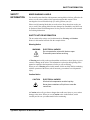
MIXER WARNING LABELS
You should become familiar with important warning labels which are affixed to the
mixer, as well as the symbols which appear throughout this manual. These
warnings have been included to help you safely perform your job.
Please read all warning labels that are on the mixer. Keep them clean so they are
easy to read. If the warning labels become damaged or unreadable, new labels can
be purchased from Fluid Management. See the parts list in the back of the manual
for ordering information.
SAFETY NOTICE INFORMATION
The two main safety notices used in this manual are Warning and Caution.
Notices in this manual will look like the example below.
Warning Notice
WARNING
ELECTRICAL HAZARD
Do not operate the mixer with the door open.
Disconnect power before servicing.
A Warning notice tells you about a hazard that could cause serious injury to you or
extensive damage to the mixer. This information is placed at the beginning of the
manual to emphasize the importance of safety to your well being.
When you see a Warning notice in this manual, read it carefully. Before continuing
with the operation of the mixer, take all necessary precautions to avoid potential
injury.
Caution Notice
CAUTION
ELECTRICAL HAZARD
All electrical components must be kept dry.
Never place containers of liquid on or near the
control box.
A Caution notice tells you about a danger that could cause injury to you or minor
damage to the mixer. When you see a Caution notice in this manual, read it
carefully and be sure you understand it before continuing.
GyroMixer Operation & Maintenance Manual
1
SAFETY INFORMATION
Information Notice
Note:
If the cabinet vibrates, loosen the locking nuts on the right
front leveling foot and slightly adjust the length.
An Information notice gives details that will assist you in efficiently using the
mixer. When you see an Information notice in this manual, know that it is there to
save you time and energy.
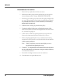
WARNINGS AND CAUTIONS
WARNINGS
•
•
•
•
•
•
The paint mixer must be properly grounded to protect the operator from
possible electrical shock. Only use a 3-prong receptacle.
Do not operate the mixer if the power cord has been cut or damaged. Keep
the cord away from open flame or heat exposure.
Properly level the paint mixer. Improper leveling may cause severe damage
to the machine during the mixing operation.
Always shut off the POWER lever and unplug the mixer from the AC
power outlet before servicing the paint mixer.
Keep hands away from moving parts.
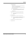
NON-EXPLOSION MODEL
• Do not use the paint mixer near flammable liquids.
• Do not mix flammable liquids containing gasoline or toxic materials.
• Do not clean the mixer with flammable solvents.
CAUTIONS
•
•
•
•
•
2
Always check to be sure that the containers are tightly sealed.
Overloading can damage the paint mixer. The maximum capacity is a 125
pound solid load.
Make sure the bail shield is properly positioned before operating the mixer.
The mixer's sliding door must be closed to operate the mixer.
Most containers one gallon or larger have bails. All such containers must
have the bail properly secured to prevent possible damage to the
equipment. As an option to using the bail shield, an elastic cord can be used
to achieve this purpose.
Fluid Management®
INTRODUCTION
INTRODUCTION
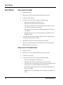
PRODUCT DESCRIPTION
The Miller GyroMixer is a versatile, automatic paint mixer designed for safety,
reliability and ease of use. Its features are as follows:
•
•
•
•
•
•
•
Improved mixing. Gyroscopic mixing at a 2:1 ratio thoroughly blends the
toughest colorants.
Robust design. Handles up to 125 pound (56.7 kg.) solid load.
Easy to service. Most service and repair procedures can be performed by
opening the door, removing the back panel or the top cover.
Simple to move and operate. Casters on the bottom of the mixer allow it to
be moved into operating position.
Safe to operate. The mixer offers improved safety features.
Universal can sizes. Handles the requirements of paint manufacturers
around the world.
Easy to load. A roller in the front of the table assists in loading the
container. A groove in the table keeps the container centered and in the
proper position.
SPECIFICATIONS
Height
39.5" (100.3 cm)
Width
32" (83.8 cm)
Depth
28" (71.0 cm) with removable shelf
26” (66.0 cm) without shelf
Shipping Weight
400 lb (181 kg)
CONTAINER DIMENSIONS
Accepts can heights from 3.5” (with bail shield removed) to 16”
GyroMixer Operation & Maintenance Manual
3
INTRODUCTION
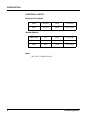
ELECTRICAL SUPPLY
Explosion-Proof Model
28708
200-240 V
60 Hz
5.5-4.6 Amps
28709
100-120 V
60 Hz
12-10.1 Amps
28988, 28989
110 V
60 Hz
11.0-9.4 Amps
30099
220 V
60 Hz
5.5-4.8 Amps
28987
220 V
50 Hz
6.5-5.7 Amps
Standard Models
Motor
1 HP, 1425/1725 RPM, 50/60 Hz
4
Fluid Management®
INTRODUCTION
EQUIPMENT MAINTENANCE LOG
RECORD MODEL NUMBER HERE: _________________________
RECORD SERIAL NUMBER HERE: _________________________
SERVICE
DATE
DESCRIPTION & PARTS REPLACED
(STATE IF UNDER WARRANTY)
GyroMixer Operation & Maintenance Manual
SERVICED
BY
5
INTRODUCTION
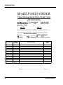
SPARE PARTS ORDER
Fluid Management Parts Order Form
Photocopy and use this form to
Mail or fax orders to:
Phone:
1(800) 462-2466
| Fax:
1(847) 537-5530
|
|
Sold To:
Ship To:
________________________ ________________________
________________________ ________________________
________________________ ________________________
________________________ ________________________
Purchase Order Number_________________
Ship Via: ______________________
Collect
Prepaid
1023 Wheeling Road
Wheeling, IL 60090
Taxable
QUANTITY
PART
NUMBER
IDEX
Tax Exempt (Fax copy of exemption certificate.)
DESCRIPTION
UNIT
PRICE
S
S
S
S
S
S
S
S
S
S
S
Comments:
____________________________________________________
____________________________________________________
____________________________________________________
_________________________________________________
Signature
6
______________
Date:
Fluid Management®
UNPACKING DIRECTIONS
UNPACKING
DIRECTIONS
INSPECT FOR DAMAGE
Inspect the shipping carton for damages. If any damage is found, notify the carrier
at once and arrange for an inspection in order to claim recovery.
Note:
Claims for damage must be made by the consignee (you).
The carrier assumes full responsibility upon acceptance of
shipment and will not entertain any claims by the consignor
(Fluid Management).
REMOVE MIXER FROM SKID
1.
Place the carton in the area where the mixer will be located.
2.
Remove the strapping and the cardboard carton stapled to the skid.
3.
Open the sliding door.
4.
Remove the two bolts holding mixer to the skid.
5.
Slide the mixer back until half of the unit is off of the skid.
6.
Carefully tilt the mixer back until its lower rear edge touches the floor
and the skid is free.
Important: Keep the weight of the mixer on its lower rear edge.
7.
Pull the skid out from under the front of the unit.
8.
Carefully tilt the mixer forward until all four casters are on the floor.
UNPACK THE MIXER
Caution
Do not operate the mixer until the shipping
inserts are removed.
1.
Open the mixer’s sliding door
2.
Remove the two (2) shipping inserts positioned in the base of the mixer.
Note:
3.
The inserts are wedged against the sides of the mixer.
Record the serial number and model number in the space provided on
page 5. (See the identification label located on the side of the mixer. It is
important data when ordering parts or servicing the mixer.)
GyroMixer Operation & Maintenance Manual
7
SETTING UP THE MIXER
SETTING UP
THE MIXER
INSTALLATION
The following instructions are for both the standard and explosion-proof models.
Refer to the boxes for special information on explosion-proof installations.
1.
Move the mixer to its permanent location.
2.
Refer to the Electrical Supply section of this manual for power
requirements.
3.
Locate the mixer as close as possible to a properly grounded outlet.
4.
Leave ample room around the paint mixer to facilitate safe operation and
routine maintenance.
Explosion-Proof Installation
•
Installation to be completed by a registered master electrician
following local codes and regulations.
•
Loosen the screws in order to remove the back cover.
•
Referring to the wiring diagram in the Service Section of this manual,
connect the power supply to the explosion-proof box.
The timer, shipped with the mixer, is located within the explosion-proof box.
It is preset for 1-1/2 minutes, but may be adjusted up to 3 minutes by
qualified service personnel.
ELECTRICAL CONNECTION
8
Caution
The unit must be plugged into a dedicated
electrical line with no other equipment using the
same circuit. DO NOT use an adapter or
extension cord with this product.
WARNING
Improper use of the grounding plug can result in
a risk of electric shock.
Fluid Management®
SETTING UP THE MIXER
Grounding
This product must be grounded. In the event of an electrical short circuit, grounding
reduces the risk of electrical shock by providing an escape for the electric current.
This product is equipped with a cord that has a grounding wire and an appropriate
grounding plug. The plug must be inserted into an outlet that is properly installed
and grounded in accordance with all local codes and ordinances.
WARNING
Check with a qualified electrician or service
person if grounding instructions are not
completely understood or if in doubt as to
whether product is properly grounded.
WARNING
Improper installation of the grounding plug can
result in a risk of electric shock. If repair or
replacement of the cord or plug is necessary, do
not connect the grounding wire to either flat
blade terminal.
The insulation wire with green or green and yellow stripes on the outer surface is
the grounding wire. Check with a qualified electrician if the grounding instructions
are not completely understood, or if in doubt about whether the product is properly
grounded. DO NOT modify the plug provided. If it will not fit into the outlet, have
the proper outlet installed by a qualified electrician.
This product is designed for use in 100 to 240 Volt operation. The power
requirements of your unit will be outlined on the nameplate.
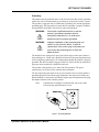
The non explosion-proof model is for use on a nominal 120-volt circuit and has a
grounding plug that looks like the plug illustrated in the figure below. Make sure
that the product is connected to an outlet having the same configuration as the plug.
No adapter should be used with this product.
Note:
If product has a nameplate for nominal 220-volt circuit, make
sure the proper grounded outlet is used.
Figure 1. Grounding Methods
GyroMixer Operation & Maintenance Manual
9
SETTING UP THE MIXER
Caution
Under no circumstances should you modify the
plug if it does not fit the outlet. Check with a
qualified electrician or serviceman if you are not
sure how to ground this unit.
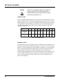
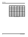
Supply Current
The table "Minimum Wire Gauge" (below) shows the recommended wire size for
home run lengths. NOTE: The smaller the gauge number, the heavier the wire.The
following chart is the wire gauge size required for the distance from the circuit box
to the grounded receptacle (for up to 15 amperes at 115V, 60 Hz). Smaller gauge
wire than shown on the table could result in a voltage drop that can effect the
operation of your unit.
Distance (feet)
25
50
100
150
20
250
300
400
500
Gauge Size
220V
14
14
12
10
10
8
8
6
6
Gauge Size
115V
14
12
8
6
6
4
4
2
2
Table 1. Minimum Wire Gauge
Extension Cords
Extension cords for 220 VAC models are not recommended. If an extension cord is
to be used, it should not be combined with others. Use only a 3-wire extension cord
that has a 3-pole grounding plug. Power should be provided by a 3-pole receptacle
that will accept the plug on the product. Make sure that your extension cord is in
good condition. It must have # 14 AWG conductors up to 25 feet long. An
extension cord no longer than 50 feet is permissible provided it has conductors of at
least # 12 AWG. It must be heavy enough to carry the current your product will
draw. An undersized cord will cause a drop in line voltage resulting in loss of
power and overheating.
10
Fluid Management®
SETTING UP THE MIXER
LEVELING
The customer must level the mixer. Although the unit is shipped on casters for ease
of positioning the mixer, all 4 feet must be extended firmly to the floor. Variations
on the floor will necessitate adjusting the leveling feet to ensure proper operation
and to minimize vibration.
CAUTION
Improper leveling may cause severe vibration
while the mixer is operating.
1.
Roll the unit into its intended location.
2.
Lower the four (4) leveling feet to the ground. Each of the four leveling
feet can be adjusted independently. Using the front of the mixer as a
position guide, turn the foot in a clockwise direction to lengthen, or in a
counter-clockwise direction to shorten.
IMPORTANT: The feet should carry the load; not the casters.
Check the stability of the mixer on the floor by making
sure that the mixer is resting on all four feet, not on its
casters. All casters must rotate freely.
3.
Verify that the mixer is level by gripping its sides and gently attempting
to rock the machine. It should not move.
4.
Lock the leveling feet into place by tightening the upper locknuts to the
mixer bottom with a 3/4" wrench.
Note:
Should additional leveling be necessary, loosen the upper
locknuts and repeat steps 2 - 3.
GyroMixer Operation & Maintenance Manual
11
SETTING UP THE MIXER
OPERATIONAL TEST
1.
Verify that the power is connected to the mixer.
2.
Open the mixer's sliding door.
3.
Slide a container into the groove on the table.
Note:
4.
Rotate the clamp handle counter clockwise first to open
the clamp arms.
Rotate the bail shield over the container bail. Remove the shield for
containers smaller than one gallon.
Note:
Failure to properly position the bail shield on containers
larger than one gallon may damage the mixer.
5.
With both hands, turn the knobs on the crank handle clockwise until
snug. Continue turning until the crank handle suddenly slips.
6.
Close the sliding door.
7.
Set the timer. (Not required for Explosion-Proof model)
Note:
8.
Move the power lever to the ON position. The unit should cycle
automatically with minimum vibration. If vibration of the cabinet
occurs, immediately depress the emergency stop switch.
Note:
9.
Make sure that the emergency stop switch is in the "on"
(pulled out) position. This can be done by turning the
knob counter clockwise.
Vibrations may occur because the unit is not properly
leveled. Try rocking the unit to make sure that all four feet
are solidly contacting the floor. Readjust the feet if
necessary. After the feet have been adjusted, reset the
emergency stop switch and continue.
When the test is complete, move the power lever to the OFF position.
10. Open the sliding door.
11. Rotate the mechanism to an upright locking position.
12. Use the knob marked "open" to turn the crank handle in the direction of
the arrow until the container is free. If necessary rotate the bail shield
away from the bail and remove the container.
12
Fluid Management®
OPERATIONS
OPERATIONS
Before operating the paint mixer, carefully read the Warnings and Cautions in the
Safety section and on the mixer, then follow these steps:
OPERATING THE MIXER
1.
Open the mixer's sliding door.
2.
Slide a container into the groove on the table. Rotate the clamp handle
counter clockwise to open the clamp arms.
3.
Position the bail shield over the container bail by rotating the upper
plate. The bail shield must be removed for containers smaller than
7-1/4" high.
Note:
CAUTION
In situations involving frequent mixing of large and small
(less then 1-gallon) containers, a special elastic cord is
supplied to fasten the bail to the can.
Failure to properly position the bail shield on
containers larger than one gallon may damage
the mixer. It is normal for the bail to move freely
behind the shield.
4.
With both hands, turn the knobs on the crank handle clockwise until
snug. Continue turning until the crank handle suddenly slips.
5.
Close the sliding door.
6.
Set the timer. (Not required for Explosion-Proof model)
7.
Make sure that the emergency stop switch is in the "on" position (pulled
out). This can be done by turning the knob counter clockwise.
EXPLOSION-PROOF MODEL
•
The timer is set to 1-1/2 minutes at the factory before
shipment.
•
See the Service Section of this manual or consult an
authorized Service Center to adjust the timer.
GyroMixer Operation & Maintenance Manual
13
OPERATIONS
8.
Move the POWER lever to the ON position.
WARNING
A safety interlock system prevents the operator
from opening the sliding door while the mixer is
running. Do not attempt to open the door while
the mixer is running.
• For an emergency stop in mid-cycle, push the EMERGENCY STOP
button.
• If vibrations occur, turn off the machine and refer to the leveling
section of this manual.
9.
When the mixer has completed its cycle, move the power lever to the
OFF position.
10. Open the sliding door.
11. Rotate the mechanism to an upright locking position.
12. Use the knob marked "open" to turn the crank handle in the direction of
the arrow until the container is free. If necessary rotate the bail shield
away from the bail and remove the container.
MIX TIMES
Material
Quantities
Approx. Mix Times *
Latex Paint
5 gal, 15L, 20L
15 - 30 seconds
Latex Paint
1 gal, 5L or less
30 - 60 seconds
Gum-Based Paint
20L
1 - 1.5 minutes
Stucco**
5 gal, 15L, 20L
1.5 - 2 minutes
*
Actual mixing times may vary depending upon material viscosity, container
size, head space, and colorant.
** When mixing stucco or other textured coatings, tip the container upsidedown, then upright again before adding colorant.
14
Fluid Management®
MAINTENANCE
MAINTENANCE
The Miller GyroMixer is designed for simple maintenance. For example, the motor
contains sealed bearings which require no lubrication.
To ensure safe, dependable operation of the paint mixer, follow the maintenance
schedule detailed below.
WARNING
Always unplug the power cord when performing
maintenance procedures.
DAILY
Immediately clean up spills with mild soap and water. A 3/4” drain pipe is
located under the front shelf to aid in cleanup.
•
Thoroughly remove soap film with clean, lukewarm water.
•
DO NOT clean this mixer with flammable solvents.
WEEKLY
•
Inspect electrical cord for damage or wear.
•
Clean/scape debris from sliding door track to maintain smooth operation.
MONTHLY
•
Clean debris from guide rods for the upper and lower moving arms.
•
Lubricate the guide rods and lead screws with graphite grease or
medium weight oil. NO grease or oil should touch the belts or pulleys.
GyroMixer Operation & Maintenance Manual
15
MAINTENANCE
SEMI-ANNUALLY
16
•
Test the secondary drive V-belt tension. Adjust, if necessary, to proper
tension (approximately 7 lbs to deflect the belt 1/4”).
•
Check the secondary drive V-belt for wear or damage. Replace if
necessary.
•
Remove the rear access panel. Test the primary drive poly V-belt
tension. Adjust, if necessary to proper tension (approximately 4-5 lbs to
deflect the belt 3/8”).
•
Check the primary drive poly V-belt for wear or damage. Replace, if
necessary.
•
Check clamping force.
- Load a container into the mixer
- Fully clamp the container into position.
- Attempt to move the container.
- If the container moves, adjusts the clamping force by tightening the
nut on the handle. Refer to the Service section for further instructions.
•
Spray silicone in the door tracks for smooth operation.
•
Inspect the door lock linkage for tightness. Refer to the Service section.
Fluid Management®
TROUBLESHOOTING
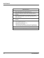
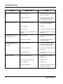
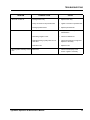
TROUBLESHOOTING
Using the chart below, locate the problem in the first column, then select the
probable cause to check and action to take from the next two columns. The
problems are arranged from the simplest to the most complex.
Where appropriate, refer to the Service section to correct the problem.
PROBLEM
Mixer does not start.
POSSIBLE CAUSE
ACTION
POWER lever is in OFF position.
•
Move POWER level to ON position.
Power supply cord is unplugged or
damaged.
•
•
Plug in cord.
Replace damaged cord.
Extension cord unplugged or inoperative.
•
Inspect extension cord. Connect or
replace if damaged.
Door is open and the safety switch has
prevented operation.
•
Close door.
Emergency stop button is pushed.
•
Turn to disengage E-stop button
Power lever not fully engaging switch.
•
Adjust the power level switch.
Replace, if necessary.
E-stop button is inoperative.
•
Check E-stop button. Replace, if
necessary
Door lock linkage needs adjusting.
•
Adjust door lock linkage.
Power relay not operating.
•
Press the test switch underneath the
power relay to close the points.
Check for loose wire connections.
Check voltage.
Replace power relay, if defective.
•
•
•
Timer knob is turned on, the
power level is in ON position, the
E-stop button is disengaged, but
mixer does not operate.
Electrical supply voltage not present.
•
Check electrical supply voltage at
the wall breaker. Correct if
necessary.
Thermal overload protection engaged due
to excessive heat in motor.
•
Turn off mixer and allow to cool
overnight. The next day test run the
mixer for 60 seconds. If the
symptom persists, replace the
motor.
GyroMixer Operation & Maintenance Manual
17
TROUBLESHOOTING
PROBLEM
Mixer operates, but does not
mix.
Mixer operates, but is noisy.
Mixer operates, but vibrates
excessively or “walks”.
Mixer operates and timer cycles
completely, but does not mix
thoroughly.
Motor runs erratically.
18
POSSIBLE CAUSE
ACTION
Belts loose or defective.
•
Check the poly V-belt and the V-belt.
Replace if necessary.
Improper timer setting.
•
Extend mixing setting. Smaller
containers and heavier viscosities
require extended mixing times.
Container not securely clamped in.
•
Check container. Reposition and
clamp securely if necessary.
Bail is not retained.
•
Retail bail.
Belt has fallen off.
•
Check belt. Reposition if necessary.
Binding occurring when rotating clamping
assembly.
•
Replace flange bearing in clamping
assembly.
Mixer is not level.
•
Verify if mixer is level. Level if
necessary.
Container is not centered.
•
Center the pail on the table and
reclamp into position.
Improper timer setting.
•
Extend mixing setting. Smaller
containers and heavier viscosities
require extended mixing times.
Incorrect drive belt tension.
•
Inspect and adjust drive belt tension
if necessary.
Secondary belt broken.
•
Check secondary belt and replace if
necessary.
Frayed or loose motor wire.
•
Tighten loose wire or replace
damage wire.
Thermal overload relay defective.
•
Replace motor.
Motor bearings bad.
•
Replace motor.
Primary belt has fallen off.
•
Check primary drive belt. Reposition
or replace, if necessary.
Fluid Management®
TROUBLESHOOTING
PROBLEM
Mixer will not shut off.
Mixer hums, but will not run.
Mixer squeaks at startup, but still
runs.
POSSIBLE CAUSE
ACTION
Damaged timer relay.
•
Replace timer relay.
Faulty connection to the potentiometer.
•
Tighten connection to potentiometer.
Damaged potentiometer.
•
Replace potentiometer.
Insufficient current.
•
Verify mixer is correctly installed to a
dedicated line.
Something caught in mixer.
•
Check for obstructions.
Defective bearing in pulleys four arms or
main drive.
•
Check each bearing for roughness.
Replace if necessary.
Defective motor.
•
Replace motor.
Belts loose.
•
Check V-belt and poly-V belt
tension. Tighten if necessary.
GyroMixer Operation & Maintenance Manual
19
SERVICE
SERVICE
GENERAL INFORMATION
If you do not feel confident about disassembling the paint mixer or replacing a part,
DO NOT ATTEMPT THE PROCEDURE. Should problems or questions arise,
contact Customer Service at Fluid Management.
Carefully read all of the instructions before you begin. For component
identification and location, refer to the Parts Section of this manual.
WARNING
ELECTRICAL HAZARD
Always shut off the POWER switch and unplug
the mixer before servicing.
CAUTION
Wear safety glasses to prevent possible injury.
Recommended Spare Parts
Belts:
Primary: 16-rub poly-V belt
Part Number 18444
Secondary: V-belt,
Part Number 18396
Bail Retainer
Part Number 20810
Rubber Pad
Part Number 18351
Special Tools
Belt tensioning gauge
Voltage meter
20
Fluid Management®
SERVICE
REMOVING THE SHEET METAL COVERS
1.
Unplug the mixer.
2.
Loosen the six (6) screws on the rear access panel and lift the panel up
and off of the screws. Set aside the panel.
3.
Remove the top cover by removing the two (2) screws which are located
under-neath the right and left back corners of the mixer cover. Save the
screws in a cup or jar.
4.
Open the sliding door.
5.
Remove the two (2) screws underneath the right and left front corners of
the mixer cover.
6.
Perform service.
7.
Replace top cover, then rear access panel.
8.
Restore power to the mixer.
REPLACING/SERVICING THE SECONDARY DRIVE V-BELT
1.
Unplug the unit.
2.
Close the sliding door approximately 4" to disengage the anti-rotation
pin.
3.
Turn the rotating assembly until upside down.
4.
Inspect the secondary drive V-belt for worn or frayed areas.
•
If the belt is in good condition, continue to set the belt tension to
approximately 1/4" deflection, as described in steps 8-9.
•
If the belt needs to be replaced continue to step 5.
5.
Using a 1-1/8" open-end wrench, loosen the nuts holding the secondary
idler bracket in place.
6.
Move the bracket forward until it is loose enough to remove the old belt.
Note:
7.
It is easier to remove the belt from the bottom first.
Beginning at the bottom, place the new V-belt into position around the
stationary pulley, up and around the two (2) idler pulleys and finally
around the secondary pulley in the front.
GyroMixer Operation & Maintenance Manual
21
SERVICE
8.
Evenly move the secondary idler bracket to set the belt tension.
Note:
9.
Belt tension should be set so that a seven (7) pound force
will deflect the belt 1/4".
Tighten the nuts holding the secondary idler bracket in place.
10. Restore power to the unit.
REPLACING/SERVICING THE PRIMARY DRIVE POLY V-BELT
1.
Unplug the unit.
2.
Remove the rear access panel by loosening the screws and lifting the
panel off the screws.
3.
Inspect the primary drive poly V-belt for worn or frayed areas.
•
If the belt is in good condition, continue to set the belt tension in
step 7.
•
If the belt is frayed or damaged, continue to step 4.
4.
Using a 9/16" wrench, loosen the two screws holding the idler bracket.
5.
Loosen the idler adjustment screw behind the idler pulley in order to
release the tension enough to remove the old belt.
6.
Place the new belt in position over the motor drive pulley, then over the
idler pulley, and finally around the driven pulley.
Note:
7.
Tighten the screw behind the idler pulley to set the belt tension. The poly
V-belt requires a 4-5 pound force to deflect the belt 3/8".
Note:
22
The belt must be fully engaged in all the grooves of both
the driven pulley and the motor drive pulley. Rotate the
motor drive pulley by hand to ensure that the belt is riding
on all the grooves.
The poly V-belt will feel looser than a standard V-belt.
8.
Tighten the two screws holding the idler bracket.
9.
Test run the mixer for 60 seconds. Check the belt tension and adjust if
necessary.
Fluid Management®
SERVICE
10. Replace the rear access panel.
11. Restore power.
ADJUSTING THE CLAMPING FORCE IN THE CLAMP HANDLE
1.
Unplug the unit.
2.
Load container into mixer.
3.
Clamp the container.
4.
Test the clamping force by pushing the container with two hands. If the
container moves, the clamping force must be adjusted as follows:
•
Remove the black plastic plug from the center of the clamp handle.
•
Using a needle-nose pliers, remove the cotter pin.
•
Tighten the locknut by turning it clockwise one or two revolutions.
•
Recheck the clamping force. If the container still moves when
clamped, tighten the nut until the pail does not move when clamped.
5.
When the clamping force is correct, place the cotter pin that was
removed in step 4 back into the mechanism.
6.
Place the plastic plug back into the center of the crank handle.
7.
Restore power to the mixer.
ADJUSTING THE DOOR LOCK LINKAGE AND START SWITCH
1.
Disconnect the power.
2.
Remove rear access panel.
3.
Remove the top cover by removing the screws holding it in place.
4.
Loosen the two (2) screws between the door lock linkage brackets.
5.
Loosen the two (2) screws in the start switch mounting bracket. (Only
for explosion-proof models.)
6.
Turn the power lever to the ON position.
7.
With the door locking bracket in a fully upright position against the
rubber stop, retighten the two (2) adjustment screws between the door
lock linkage brackets.
GyroMixer Operation & Maintenance Manual
23
SERVICE
CAUTION:
To avoid breakage, do not over actuate the power
lever.
8.
After tightening the screws in step 7 and with the power lever still in the
ON position, slide the start switch bracket toward the front of the mixer
until fully depressed by the roller. Tighten the screws while the switch is
in this position.
9.
Replace the top cover and rear access panel. Tighten the screws.
10. Restore the power.
REPLACING THE ROLLER
1.
Unplug the mixer.
2.
Open the sliding door.
3.
Remove the screw on each end of the roller bracket. Use a needle-nose
pliers to hold the plastic bushing while removing the Phillips screw.
4.
Remove and discard the old roller.
5.
Place the plastic bushings in the ends of the new roller.
6.
Place the roller on the roller bracket.
7.
Using the needle-nose pliers to keep the plastic bushing from rotating,
tighten the screws on the roller bracket.
8.
Close the sliding door.
9.
Restore power to the mixer.
INSTALLING THE UPPER TABLE PAD
24
1.
Unplug the electrical cord.
2.
Raise the sliding door.
3.
Turn the rotating assembly upside down.
4.
Use a scraper to loosen the pad around the edges.
5.
Pull off the old pad.
Fluid Management®
SERVICE
6.
Using mineral spirits or similar non-flammable liquid, remove the old
adhesive residue left on the table.
7.
Remove the adhesive paper on the back of the new pad.
8.
Carefully aligning the new pad, attach the pad to the upper table. Apply
pressure from the center outward and over the entire surface of the pad
until it is secure.
9.
Close the sliding door.
10. Restore power to the mixer.
REPLACING THE SLIDING DOOR
1.
Unplug the mixer.
2.
Remove the rear access panel.
3.
Remove the top cover.
TOP COVER
TRACK
Figure 2. Door Covers
4.
Remove the two (2) screws and door stop from the right track. (Figure 3,
as viewed from back.)
GyroMixer Operation & Maintenance Manual
25
SERVICE
5.
Close the sliding door.
TRACK
DOOR STOP
Figure 3. Door Stop
6.
Working at the back of the mixer, gently slide the door out of the two
notches in the top of the right and left side door tracks (see Figure 3).
Set door aside.
7.
Clean the door tracks.
8.
Place the new door on a clean, flat surface.
9.
Vertically apply masking tape to the slats in order to keep the slats in
line.
10. Feed the replacement sliding door into the two notches on the top right
and left side door tracks.
11. Gently glide the door all the way down.
12. Remove the masking tape.
13. Test the operation of the door by opening and closing. Make
adjustments, as necessary.
14. Mount the door stop back onto the right track with the two (2) screws.
15. Reassemble the top cover and rear access panel.
16. Restore power to the mixer.
26
Fluid Management®
SERVICE
REMOVING THE MOTOR
1.
Unplug the electrical cord.
2.
Remove the rear access panel and top cover by removing the screws.
3.
Loosen, but do not remove, the idler pulley.
4.
Remove the belt from the motor pulley.
5.
Loosen the screw holding the conduit box cover in place.
6.
Remove the conduit box cover in order to disconnect the following three
wires:
• Brown (L1) and blue (L2) wires which are secured with wire nuts.
•
Ground wire held with in place with a green screw.
7.
Inside the conduit box, remove the nut securing the tubing connector to
the conduit box and separate the connector from the conduit box.
8.
Holding the motor securely, remove the four (4) screws holding the
motor to the motor mounting bracket. Save the screws. Discard the
motor.
9.
For reassembly purposes, measure the position of the motor drive pulley
before removing it from the driveshaft: measure from the face of the
motor to the edge of the pulley.
Note:
The key should be flush with the shaft.
10. Loosen the motor drive pulley set screw and remove the pulley. Save the
circular push-on retaining ring for reassembly.
11. Set the pulley aside for later use.
12. Discard the old motor.
GyroMixer Operation & Maintenance Manual
27
SERVICE
REASSEMBLING THE MOTOR
1.
Remove the key taped to the side of the new motor.
2.
Slide the motor drive pulley onto the shaft and into the same position
measured during removal in Step 9, REMOVING THE MOTOR.
3.
Place the key inside the keyway in the motor drive pulley and tighten the
set screw. The key should be seated in the driveshaft keyway. It should
be positioned in the same way as on the old motor (as noted in Step 9,
REMOVING THE MOTOR).
4.
Push the circular retaining ring into the motor pulley.
5.
Viewing the shaft end of the motor, confirm that the rotation of the
motor is CW (clockwise). Refer to the diagram on the side of the motor
for a detailed wiring diagram.
6.
Lift the motor, with the wires pointing downward, into position and
fasten to the motor mounting bracket with the four (4) screws.
7.
Before completely tightening the screws, manually turn the rotating
mechanism one full revolution to verify that the motor does not interfere
with the rotating mechanism.
Note:
If there is interference, move the motor slightly to correct
the problem before tightening the screws.
8.
Connect L1, L2, and ground wires to the motor. Refer to the diagram on
the side of the motor to verify the motor wiring for clockwise rotation as
viewed from the shaft end.
9.
Reassemble the tubing connector nut onto the conduit box.
10. Close the motor cover plate with the screw.
28
Fluid Management®
SERVICE
11. Perform a motor test:
• Plug in the mixer.
•
Turn on the motor and confirm that the rotation of the motor is
clockwise, as viewed from the shaft end.
•
If not, refer to the wiring diagram on the side of the motor and
correct the rotation setting.
Note:
•
If the diagram does not specify, the default is as viewed
from the lead end where the power wires are located.
Unplug the mixer.
12. Replace the belt on the motor pulley and set the belt tension.
Note:
The tension on the poly V-belt will fell looser than a
standard V-belt.
13. Plug in the mixer.
14. Test run the mixer for 60 seconds to check the belt tension.
Note:
If necessary, unplug the mixer and adjust the tension. This
is also the time to adjust the motor drive pulley, if
required.
15. Reassemble the top cover and the rear access panel.
16. Plug in the mixer.
GyroMixer Operation & Maintenance Manual
29
ELECTRICAL
ELECTRICAL
REPLACING THE TIMER
1.
Unplug the mixer.
2.
Remove the rear access panel and the electrical cover plate.
3.
Locate the timer module.
4.
From the back of the mixer, perform the following steps:
• Make a wiring diagram or label the wires.
•
Disconnect all wire connections at the timer.
•
The timer is secured to a screw on the back panel with one (1) nut.
Use a socket wrench to remove the nut.
•
Place the new timer on the screw and hand tighten the nut. Do not
over tighten.
•
Reattach the new timer to the connecting wires according to your
diagram or labels.
5.
Verify that all connections fit tightly. Repair any loose connections by
crimping or replacing the loose ones.
6.
Reinstall the electrical cover plate and rear access panel.
7.
Plug in the electrical cord and verify that the mixer operates properly.
Make adjustments, if necessary.
REPLACING THE POWER RELAY
30
1.
Unplug the mixer.
2.
Remove the rear access panel and the electrical cover plate.
3.
Locate the power relay.
4.
From the back of the mixer, perform the following steps:
• Make a wiring diagram or label the wires.
•
Disconnect all six (6) wire connections at the power relay.
•
The power relay is secured to two (2) screws on the back panel with
two (2) nuts. Use a socket wrench to remove the nuts.
•
Place the new power relay on the screws and hand tighten the nuts.
Do not over tighten.
•
Reattach the six (6) connecting wires according to your diagram or
labels.
Fluid Management®
ELECTRICAL
5.
Verify that all connections fit tightly. Repair any loose connections by
crimping or replacing the loose ones.
6.
Reinstall the electrical cover plate and the rear access panel.
7.
Plug in the electrical cord and verify that the mixer operates properly.
Make adjustments, if necessary.
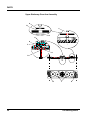
ELECTRICAL DRAWINGS
T1
K1
S1
L1
A B
L2
GND
EMERGENCY
STOP
4
S2
C D
1
START
SWITCH
0
6
2
4
1
+
5
CYCLE
COUNTER
M
CYCLE
COUNTER
M
-
3
ELECTRICAL SCHEMATIC, 100-120V, 50/60Hz
NOTE: THE CONNECTIONS SHOWN FOR S1 & S2
ARE LABELS ONLY. REFER TO TABLE FOR
CORRESPONDING CONNECTIONS.
T1
K1
L1
S1
A B
L2
GND
EMERGENCY
STOP
S2
C D
6
1
8
2
4
1
+
5
START
SWITCH
0
3
2 4
ELECTRICAL SCHEMATIC, 200-240V, 50/60Hz
-
Figure 4. Electrical Schematic
GyroMixer Operation & Maintenance Manual
31
ELECTRICAL
Switch
Terminal
Standard
Intn’l
X-Proof
US
X-Proof
X-Proof
S1
A
21
1
N.C.
---
S1
B
22
2
N.C.
---
S2
C
13
3
N.O.
---
S2
D
14
4
N.O.
---
S1
A
21
---
---
N.C.
S1
B
22
---
---
N.C.
S2
C
13
---
---
N.O.
S2
D
14
---
---
N.O.
Table 2. Electrical Schematic
32
Fluid Management®
PARTS
PARTS
This section is designed to assist you in performing service functions and
identifying parts. All repairs must be performed by qualified service personnel.
TERMS
Unless prior arrangements have been made, parts will be shipped UPS. All prices
are F.O.B. Wheeling, Illinois, and are subject to change without notice.In all
correspondence or phone orders for parts, please state model number and serial
number of the equipment.
RETURNS
No parts are to be returned without prior authorization. A Returned Goods
Authorization number is required.
WARRANTY SERVICE
Defective parts are replaced under warranty for a period of two years. Labor on
major components is covered for a period of one year. The procedure is as follows:
•
•
Call the Customer Service department at 1(800) 462-2466. Have the serial
number and model number ready.
If the problem can be handled over the phone, an RGA(Return Goods
Authorization) number will be assigned.You must return defective parts to
avoid billing.
NON-WARRANTY SERVICE
•
Call the Customer Service department at 1(800) 462-2466. Have the model
number ready.
GyroMixer Operation & Maintenance Manual
33
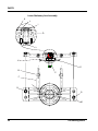
PARTS
F
E
B
H
D
G
A
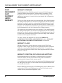
34
C
Fluid Management ®
PARTS
PART NO
DESCRIPTION
A
18307
BACK PANEL
1
B
F29082-01
DIGITIAL TIMER PANEL
1
C
20811
SCREW, PAN HEAD WITH EXTERNAL LOCK WASHER
(10-24 X 1/2”, PHILLIPS) BACK PANEL MOUNTING SCREW
6
D
29546
STANDARD COVER ASSEMBLY
4
E
4980024
DECAL, CONTROL PANEL
STANDARD GYROMIXER
1
F
4980025
DECAL, WARNING/NOTICE
STANDARD GYROMIXER
1
G
4980029
DECAL, EMERGENCY STOP SWITCH
STANDARD GYROMIXER
1
H
28232
ON/OFF EMERGENCY STOP KIT
1
H
26050
EMERGENCY STOP - SWITCH ONLY
1
H
26052
EMERGENCY STOP - SWITCH MECHANISM ONLY
1
19337
TIMER KNOB (NOT SHOWN)
EXPLOSION PROOF GYROMIXER ONLY
1
1980026
DECAL, WARNING / NOTICE (NOT SHOWN)
EXPLOSION-PROOF GYROMIXER ONLY
4980067
DECAL, CONTROL PANEL (NOT SHOWN)
EXPLOSION-PROOF GYROMIXER ONLY
GyroMixer Operation & Maintenance Manual
NO REQ
1
35
PARTS
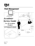
J, K
A
F
L
I
D
H
M
E
G
B
36
C
Fluid Management ®
PARTS
PART NO
DESCRIPTION
NO REQ
A
F0113
STAINLESS STEEL THREADED STANDARD SCREW
1
B
18334
SHAFT, HEX, SOUPLER, 11” HEXX4.66LG
1
C
18396
SECONDARY DRIVE V-BELT
1
D
18442
POLY-V MOTOR PULLEY
STANDARD GYROMIXER
1
E
18444
MAIN DRIVE POLY-V BELT, 820 J 16
1
F
18450
EMERGENCY STOP SWITCH COVER
1
G
18490
CABINET, STANDARD MACHINE
1
H
4980029
DECAL, E-STOP, STANDARD GYROMIXER
1
I
28232
ON/OFF EMERGENCY STOP KIT
1
J
5108219
BULB HOLDER AND START SWITCH MECHANISM
STANDARD GYROMIXER
1
K
5108330
START PUSH BUTTON, GREEN
STANDARD GYROMIXER
1
L
21516
STANDARD COVER ASSEMBLY
1
M
F0103408
SCREW, HEX, 1/4-20X1/2, FLANGE
1
19345
POTENTOMETER, 1.5 MEGOHM (NOT SHOWN)
EXPLOSION PROOF GYROMIXER ONLY
4
F0116A406
SCREW, SET, 1/4-20X3/8, SOCKET CAP (NOT SHOWN)
1
GyroMixer Operation & Maintenance Manual
37
PARTS
G
F
H
E
I
J
D
000000
C
B
A
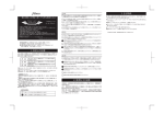
38
Fluid Management ®
PARTS
PART NO
DESCRIPTION
NO REQ
A
18370
INCOMING CORD, 12 FEET; STANDARD GYROMIXER
1
B
18444
MAIN DRIVE POLY-V BELT, 820 J
1
C
118487
IDLER ADJUSTMENT BRACKET
1
D
26458
MOTOR (1 HP, 100-200V/200-240V, 50/60 HZ - 1425/1725 RPM)
STANDARD GYROMIXER
1
D
20824
MOTOR (1 HP, 115/230VAC, 60 HZ - 1425/1725 RPM)
EXPLOSION PROOF GYROMIXER ONLY
1
E
119348
CABINET WIRING HARNESS
STANDARD 100-120V GYROMIXER
1
F
32563
SOLID STATE INTERVAL TIMER 100-120V
STANDARD GYROMIXER
1
F
32564
SOLID STATE INTERVAL TIMER 220-230V
EXPLOSION PROOF GYROMIXER ONLY
1
G
4000096
NUT, HEX (1/4-20, WITH NYLON PATCH)
ANTI-ROTATION ASSEMBLY AND TIMER MOUNTING SCREW
AVAILABLE ONLY IN PACKAGE OF TWELVE - PART NO. S4000438
5
H
5608204
LOW VOLTAGE POWER RELAY
STANDARD AND EXPLOSION PROOF GYROMIXER
NOTE: THE LOW VOLTAGE POWER RELAY IS USED ON 100-120VOLT
EXPLOSION PROOF GYROMIXERS AND MUST BE INSTALLED IN AN
EXPLOSION PROOF BOX.
1
I
F0103616
SCREW, HEX SERRATED FLANGE (3/8-16 X 1")
TWO IDLER ADJUSTMENT BRACKET MOUNTING SCREW AND FOUR
MOTOR MOUNTING SCREWS
6
J
F01191008
SCREW, HEX SERRATED FLANGE; NO. 10 X 1/2”, WITH NYLON PATCH
ELECTRICAL COVER MOUNTING SCREW
4
20446
ELECTRICAL COVER (NOT SHOWN)
1
GyroMixer Operation & Maintenance Manual
39
PARTS
R
P
H
G
N
E
F
I
Q
C
M
O
A
J
L
M
D
K
B
40
Fluid Management ®
PARTS
PART NO
DESCRIPTION
A
17268
SEALED BEARING (35MM ID)
2
B
18354
SWIVEL CASTER
4
C
18387
STAINLESS STEEL FRONT SHELF
1
D
18400
ANTI-ROTATION ASSEMBLY
1
E
18441
PRIMARY AXIS SHAFT
1
F
18443
MAIN DRIVE POLY-V PULLEY (19” DIAMETER)
1
G
18452
STATIONARY PULLEY
1
H
16077
WASHER (3/8” ID X 1" OD)
(FOR STATIONARY PULLEY MOUNTING SCREWS)
6
I
17279
MAIN DRIVE PULLEY WASHER
1
J
18480
FRONT PANEL
1
K
21515
LEVELING FOOT ASSEMBLY
4
L
4000096
NUT, HEX (1/4-20, WITH NYLON PATCH)
ANTI-ROTATION ASSEMBLY AND TIMER MOUNTING SCREW
AVAILABLE ONLY IN PACKAGE OF TWELVE - PART NO. S4000438
4
M
4000370
SCREW, HEX HEAD CAP (5/16-18 X 3/4”, WITH NYLON PATCH)
ONE - MAIN DRIVE POLY-V PULLEY MOUNTING SCREW AND SIXTEEN
SWIVEL CASTER MOUNTING SCREWS
17
N
4000126
NUT, HEX (5/16-18, WITH NYLON PATCH)
FOR STATIONARY PULLEY MOUNTING SCREWS
AVAILABLE ONLY IN PACKAGE OF TWELVE - PART NO. S4000441
6
O
F0100A4P12
SCREW, BUTTON HEAD CAP (1/4-20 X 3/4”, SOCKET, WITH NYLON PATCH)
FRONT PANEL AND SHELF MOUNTING SCREWS
1
P
F0106A5B44
SCREW, SOCKET HEAD CAP (5/16-18 X 2-3/4”)
STATIONARY PULLEY MOUNTING SCREWS
6
Q
F0104A6B14
SCREW (3-8-16 x .875) BLACK OXIDE WITH PATCH
1
R
18305
START SWITCH SPRING MOUNTING BRACKET EXPLOSION PROOF
GYROMIXER ONLY
1
GyroMixer Operation & Maintenance Manual
NO REQ
41
PARTS
A
H
C
B
E
D
F
G
42
Fluid Management ®
PARTS
PART NO
DESCRIPTION
A
28533
SLATTED FRONT DOOR ASSEMBLY
1
B
18487
IDLER ADJUSTMENT BRACKET
1
C
19437
SCREW, HEX HEAD (3/8-16 X 3-1/2”)
IDLER ADJUSTMENT BRACKET MOUNTING SCREW
1
D
20459
MAIN DRIVE IDLER PULLEY1
1
E
F0103616
SCREW, HEX SERRATED FLANGE (3/8-16 X 1")
TWO - IDLER ADJUSTMENT BRACKET MOUNTING SCREW AND FOUR MOTOR MOUNTING SCREWS
6
F
F0103824
SCREW, HEX SERRATED FLANGE (1/2-13 X 1-1/2”)
MAIN IDLER PULLEY MOUNTING SCREW
1
G
29536
SOLENOID ASSEMBLY, 120VAC, 60 HZ
1
H
26065
INTERLOCK SWITCH ASSEMBLY
1
GyroMixer Operation & Maintenance Manual
NO REQ
43
PARTS
B
D
A
G
C
E
F
H
H
44
Fluid Management ®
PARTS
PART NO
DESCRIPTION
A
18306
START SWITCH SPRING PIN
1
B
18325
DOOR LOCKING BRACKET
1
C
21518
START SWITCH HANDLE ASSEMBLY
1
D
18365
DOOR LOCK MOUNTING BLOCK
11
E
18393
START HANDLE MOUNTING BLOCK
1
F
20445
START HANDLE SPRING
1
G
20813
DOOR LOCKING LINKAGE
1
H
F0103408
SCREW HH (1/4-20X1/5 LG, LOCKING, SERRATED)
4
GyroMixer Operation & Maintenance Manual
NO REQ
45
PARTS
CABINET & ELECTRIC COMPONENTS NOT SHOWN
46
PART NO
DESCRIPTION
NO REQ
18305
START SWITCH SPRING MOUNTING BRACKET PIN
1
18365
DOOR LOCK MOUNTING BRACKET
1
18393
START HANDLE MOUNTING BLOCK
1
19333
TIMER RELAY AND CONTROL MOUNTING BRACKET, EXPLOSION-PROOF
1
19334
TIMER MOUNTING BRACKET
EXPLOSION-PROOF GYROMIXER ONLY
1
19340
CABINET ASSEMBLY
EXPLOSION-PROOF GYROMIXER ONLY
1
19347
POTENTIOMETER (2.0 MEGOHM)
EXPLOSION-PROOF GYROMIXER ONLY
1
19351
SOLID STATE INTERVAL TIMER (EXPLOSION-PROOF 200-240V)
NOTE: THE INTERVAL TIMER MUST BE INSTALLED IN AN EXPLOSIONPROOF BOX ON THE EXPLOSION-PROOF MIXER.
1
19354
DOUBLE GANG EXPLOSION-PROOF BOX
EXPLOSION-PROOF GYROMIXER ONLY
1
19355
EMERGENCY STOP SWITCH
EXPLOSION-PROOF GYROMIXER ONLY
1
19356
MOMENTARY START SWITCH
EXPLOSION-PROOF GYROMIXER ONLY
1
20804
CABINET WIRING HARNESS 200-240V
EXPLOSION-PROOF GYROMIXER ONLY
1
20806
EXPLOSION-PROOF CONDUIT BOX
EXPLOSION-PROOF GYROMIXER ONLY
1
20812
DOOR STOP BRACKET
1
20813
DOOR LOCKING LINKAGE
1
21515
LEVELING FOOT ASSEMBLY
1
21516
COVER ASSEMBLY
STANDARD GYROMIXER
1
Fluid Management ®
PARTS
21517
COVER ASSEMBLY
EXPLOSION-PROOF GYROMIXER ONLY
1
21518
START SWITCH HANDLE ASSEMBLY, INCLUDES DOWEL PIN AND ROLLER
1
21519
STATIONARY PULLEY ASSEMBLY, INCLUDES BEARINGS AND PRIMARY
AXIS SHAFT
1
21521
DOOR LOCK MOUNTING ASSEMBLY
1
4980026
DECAL, WARNING/NOTICE
EXPLOSION-PROOF GYROMIXER ONLY
1
26052
ON/OFF EMERGENCY STOP SWITCH MECHANISM
STANDARD GYROMIXER
1
5108219
BULB HOLDER AND START SWITCH MECHANISM
STANDARD GYROMIXER
1
5608300
HIGH VOLTAGE POWER RELAY (EXPLOSION-PROOF)
NOTE: THE HIGH VOLTAGE POWER RELAY IS USED ON 200-240 VOLT
EXPLOSION-PROOF
1
4000370
CREW, HEX HEAD CAP (5/16-18 X 3/4” WITH NYLNO PATCH)(1 MAIN DRIVE
POLY-V PULLEY MOUNTING & 16 CASTERS)
1
F0103408
SCREW, HEX SERRATED FLANGE (1/4-20 X 1/2”, WITH NYLON PATCH)
(FOUR - COVER ASSEMBLY MOUNTING SCREW AND TWO - DOOR STOP
BRACKET)
6
GyroMixer Operation & Maintenance Manual
47
PARTS
Upper Stationary Arm Assembly
C
E
D
F
O
K
Q
I
Lower Moving Arm Assembly
M
F
E
B
H
J
O
N
P
M
I
A
L
48
G
R
Fluid Management ®
PARTS
PART NO
DESCRIPTION
A
17268
BEARING, SEALED (35MM)
2
B
18312
LOWER MOVING ARM
1
C
18313
UPPER ARM TABLE
1
D
18316
UPPER ARM LEAD SCREW BUSHING
2
E
18317
GUIDE ROD BUSHING (1.004 X 1.25 X 1.5)
2
F
18332
LOWER TABLE
1
G
18333
DRIVE SHAFT
1
H
18336
LOWER ARM LEAD SCREW ASSEMBLY
2
18339
UPPER TABLE PAD (NOT SHOWN)
2
I
18438
WASHER (1/4” ID X 3/4” OD)
4
J
19317
LOWER ARM ROLLER MOUNTING BRACKET
1
K
20814
BAIL SHIELD
1
21520
UPPER TABLE KIT, INCLUDES UPPER TABLE & UPPER TABLE PAD
(NOT SHOWN)
1
21522
UPPER MOVING ARM, WITH BEARINGS & TABLE HUB (NOT SHOWN)
1
21523
UPPER TABLE HUB ASSEMBLY (NOT SHOWN)
1
L
21524
LOWER TABLE HUB KIT, INCLUDES DOWEL PINS, HUB AND LOWER TABLE
1
M
4000255
SCREW (5/16-18 X 1/2 SOCKET)
4
N
5103153
PLASTIC ROLLER ASSEMBLY, INCLUDES BEARINGS, TUBE, SHAFT
AND SCREWS
1
O
F01050410
SCREW, SHOULDER (1/4” X 5/8” WITH NYLON PATCH)
4
P
F001101
RETAINING RING (80MM INTERNAL)
1
Q
F0100A4B12
SCREW, BUTTON HEAD CAP (10-24 X 5)
3
R
F012703
RETAINING RING, INTERNAL (5/8” CRESCENT)
1
GyroMixer Operation & Maintenance Manual
NO REQ
49
PARTS
Lower Stationary Arm Assembly
K
J
I
D
L
H
E
B
C
F
G
G
M
50
Fluid Management ®
PARTS
PART NO
DESCRIPTION
A
01007
ROLL PIN (3/16 X 1” SS)
2
B
03163
NUT (3/4-10 HEX)
2
C
18334
SHAFT COUPLER (1” HEX)
1
D
18392
SEALED BALL GEARING
1
E
18397
SECONDARY PULLEY
1
F
18456
SECONDARY IDLER SHAFT
2
G
20454
BALL BEARING, R8ZZ (5” ID X 1.125 OD)
2
H
21528
PULLEY HUB ASSEMBLY, INCLUDES ROLL PINS, HUB, PULLEY AND
LOWER ARM
1
I
F00101
RETAINING RING, EXTERNAL (. 1”)
2
J
F000904
RETAINING RING, EXTERNAL (1.5”)
1
K
F001101
RETAINING RING, INTERNAL (80MM)
1
L
F0100A4B12
SCREW (1/4-20)
1
M
21529
LOWER STATIONARY ARM ASSEMBLY, INCLUDES BEARINGS AND HUB
1
M
18391
LOWER STATIONARY ARM
1
GyroMixer Operation & Maintenance Manual
NO REQ
51
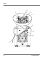
PARTS
Rotary Assembly
Q
I
J
V
P
H
N
O
G
A
M
R
U
B
C
D
F
U
L
S
52
Fluid Management ®
PARTS
PART NO
DESCRIPTION
NO REQ
A
01113
SCREW (8-32 X 3/8)
4
B
18310
UPPER MOVING ARM ASSEMBLY, INCLUDES BUSHINGS, SCREWS,
MOVING ARM & UPPER TABLE
1
C
18322
YOKE
1
D
18323
ROD GUIDE
2
E
18324
LEAD SCREW
2
F
18330
LOWER MOVING ARM ASSEMBLY (INCLUDES BUSHINGS, SCREWS,
LOWER MOVING ARM & TABLE)
1
G
18341
PLANE BUSHING (1/2” X 5/8” OD X 5/16”)
1
H
18342
COMPRESION SPRING (0.6 OD, X 1”)
4
I
22876
PIN
1
J
22875
NUT, SLOTTED
1
K
18340
CLAMP HANDLE ASSEMBLY
1
L
18390
LOWER STATIONARY ARM ASSEMBLY
1
M
18420
UPPER STATIONARY CLAMPING GEAR ARM ASSEMBLY, INCLUDES
BEARINGS, BUSHINGS, CLAMPING PRESSURE PLATES, GEAR ARM
ASSEMBLY & GEARS
1
N
18422
GEAR ARM COVER
1
18430
TORSION SPRING (NOT SHOWN)
1
O
25279
RATCHET, CLAMP LOCKING
1
P
18447
THRUST BUSHING (1/2” X 1” OD)
3
Q
18459
PLUG, POLYETHYLENE (2”)
1
21525
LOWER MOVING ARM ASSEMBLY, INCLUDES BEARINGS AND HUB
(NOT SHOWN)
1
21526
CLAMP HANDLE ASSEMBLY, INCLUDES BUSHINGS AND DOWL PIN
(NOT SHOWN)
1
21527
LOCKING LINKAGE KIT, INCLUDES DOWEL PIN, PAWL SCREWS AND
SPRING (NOT SHOWN)
1
R
F0103816
SCREW (1/2-13 X 1”)
2
S
F0103824
SCREW (1/2-13 X 1-1/2”)
2
F0115A0724
DOWEL PIN (1/2-13 X 1-1/2”) (NOT SHOWN)
2
T
F0100A3B08
SCREW (10-24 X 1/2”)
8
U
F01260812062
SPACER, 1/2” ID X 3/4” OD X 1/8”
6
GyroMixer Operation & Maintenance Manual
53
PARTS
Secondary Idler Pully Assembly
E
A
C
B
D
F
54
Fluid Management ®
PARTS
PART NO
DESCRIPTION
NO REQ
A
03163
NUT (3/4-10 HEX)
2
B
18453
V-IDLER PULLEY WITH BEARINGS
2
C
18454
SECONDARY IDLER MOUNTING BRACKET118457SECONDARY IDLER
BUSHING
1
D
18457
SECONDARY IDLER BUSHING
4
E
18460
IDLER ASSEMBLY, SECONDARY(INCLUDES BUSHINGS, MOUNTING
BRACKET, PULLEYS, AND SCREWS)
1
F
4000227
HEX SCREW (3/8-16 X 1.25)
2
GyroMixer Operation & Maintenance Manual
55
PARTS
Upper Stationary Gear Arm Assembly
A
B
C
H
K
G
F
I
D
18421
E
56
J
E
Fluid Management ®
PARTS
PART NO
DESCRIPTION
NO REQ
A
18301
LEAD SCREW CAP
2
B
18302
KEY, 48 TOOTH GEAR (1/8” X 1/8” X 1/4”)
2
18311
FEMALE CLAMPING PRESSURE PLATE (NOT SHOWN)
1
C
18319
NYLON SPACER (3/8” X 3/4” X 1/8”)
4
D
18343
CLAMPING HANDLE PIN
1
18398
BRASS 72 TOOTH GEAR (NOT SHOWN)
EXPLOSION PROOF GYROMIXER ONLY
2
E
18399
STEEL 48 TOOTH GEAR
2
F
18427
THRUST BUSHING (3/8” ID X 3/4” OD)
4
18428
FLANGE BUSHING, 3/8” ID X 1/2” OD 5/16” (NOT SHOWN)
G
18429
FLANGE BEARING (1/2” ID X 5/18” OD X 1/2”)
1
H
18447
THRUST BUSHING (1/2” ID X 1” OD)
2
18451
BRASS 48 TOOTH GEAR (NOT SHOWN)
EXPLOSION PROOF GYROMIXER ONLY
2
20454
RADIAL BALL BEARING (1/2” X 1-1/8:) (NOT SHOWN)
2
21530
GEAR ARM ASSEMBLY(INCLUDES DOWEL PINS)
1
21531
UPPER STATIONARY GEAR ARM ASSEMBLY, COMPLETE,
INCLUDES BEARINGS, BUSHINGS, CLAMPING PRESSURE PLATES,
GEAT ARM ASSEMBLY AND GEARS (NOT SHOWN)
STANDARD GYROMIXER
1
21532
UPPER STATIONARY GEAR ARM ASSEMBLY, COMPLETE,
INCLUDES BEARINGS, BUSHINGS, CLAMPING PRESSURE PLATES,
GEAT ARM ASSEMBLY AND GEARS (NOT SHOWN)
EXPLOSION PROOF GYROMIXER ONLY
1
J
21533
STEEL 72 TOOTH CENTER GEAR WITH TAPPED HOLES,
INCLUDES BUSHINGS
1
K
21534
STEEL 72 TOOTH GEAR WITH BUSHING
(TWO FOR EXPLOSION-PROOF, FOUR FOR STANDARD)
2/4
21535
MALE CLAMPING PRESSURE PLATE ASSEMBLY, INCLUDES
BUSHINGS (NOT SHOWN) STANDARD GYROMIXER
1
21536
MALE CLAMPING PRESSURE PLATE ASSEMBLY, INCLUDES
BUSHINGS (NOT SHOWN) EXPLOSION PROOF GYROMIXER ONLY
1
F0024A3B08
SCREW, FLANGE HEAD CAP (10-32 X 1/2” SOCKET WITH NYLON
PATCH)
6
I
L
GyroMixer Operation & Maintenance Manual
57
FLUID MANAGEMENT PAINT EQUIPMENT LIMITED WARRANTY
FLUID
MANAGEMENT
PAINT
EQUIPMENT
LIMITED
WARRANTY
WARRANTY COVERAGE
Fluid Management, Inc. ("Fluid Management") warrants all Fluid Management
Accutinters, Manual Paint Dispensers, and Paint Mixers and Shakers ("Paint
Equipment") to be free of defects in material and workmanship during normal
operation, use and service for a period of two years from the date of shipment by
Fluid Management.
The first year of the warranty period covers parts and labor. If any Paint Equipment
fails during normal operation, use and service during the first year of the warranty
period due to a defect in material or workmanship, Fluid Management will repair
the defective Paint Equipment and replace any defective parts at no charge to the
Customer. The warranty repairs and defective parts replacement will be carried out
by Fluid Management or one of its Authorized Service Representatives.
The second year of the warranty period covers parts only. If any Paint Equipment
fails during normal operation, use and service during the first year of the warranty
period due to a defect in material or workmanship, Fluid Management will provide
Customer with a replacement for any defective parts at no charge to the Customer.
Customer will be responsible for all labor.
The above warranty and obligations are subject to the WARRANTY
CONDITIONS, EXCLUSIONS AND LIMITATIONS and the WARRANTY
DISCLAIMERS AND LIABILITY LIMITATIONS set forth below.
WARRANTY CLAIMS
Warranty claims must be asserted during the warranty period. While Paint
Equipment is under warranty, no repair or part replacement should be undertaken
without first contacting Fluid Management at 800-462-2466. To expedite the
process, the model and serial numbers of the Paint Equipment should be available
at the time of the call.
WARRANTY CONDITIONS, EXCLUSIONS AND LIMITATIONS
Fluid Management shall have no liability or obligation under its warranty in
connection with any warranty claim asserted or any failure or malfunction
occurring after the expiration of the warranty period.
As a condition to any warranty repair or part replacement, Fluid Management shall
have the right to first inspect, test and evaluate the Paint Equipment and parts that
are claimed to be defective.
Return of Paint Equipment and parts to Fluid Management requires a Return Goods
Authorization (RGA) from Fluid Management, and the RGA number must be
included with any returned Paint Equipment or part.
58
Fluid Management ®
FLUID MANAGEMENT PAINT EQUIPMENT LIMITED WARRANTY
Customer shall be required to provide Fluid Management and its Authorized
Service Representatives with all information that any of them may request
concerning the maintenance, operation, use, service, failure or malfunction of Paint
Equipment and parts that are claimed to be defective.
Fluid Management may use reconditioned parts for warranty repairs and parts
replacement.
Warranty repairs and part replacement do not extend the warranty period for Paint
Equipment and repaired Paint Equipment and replacement parts are warranted only
for the remainder of the original warranty period.
Any repair or replacement requested as a warranty repair or replacement that is not
covered by Fluid Management's warranty will be billed to Customer as nonwarranty repair or replacement on a time and materials basis.
Fluid Management's warranty transfers to the new owner with transfer of
ownership Paint Equipment. It is the responsibility of new owner to notify Fluid
Management at 1-800-462-2466 of the transfer of ownership of Paint Equipment.
Transfer of ownership does not extend the warranty period.
Fluid Management's warranty does not cover, extend or apply to, or include:
•
Computer or computer-related equipment such as laptops,
monitors and printers and other third-party equipment supplied
with Paint Equipment (In the case of computer and computerrelated equipment such as laptops, monitors or printer, and other
third-party equipment, any warranty is limited to a pass through to
Customer of any warranty received from the equipment
manufacture, and is subject to whatever terms, conditions and
limitations are imposed by the equipment manufacturer)
•
Third-party software (In the case of third-party software, any
warranty is limited to a pass through to Customer of any warranty
received from the software provider and is subject to whatever
terms, conditions and limitations are imposed by the software
provider)
•
Normal wear and tear
•
Any Paint Equipment or part that fails or malfunctions due to any
computer or computer-related equipment, other peripheral
equipment, third-party software or software or equipment
provided by Customer or a third party
•
Any Paint Equipment or part failure or malfunction that Fluid
Management or one of its Authorized Service Representatives
determines to have been caused by or attributable to damage
GyroMixer Operation & Maintenance Manual
59
FLUID MANAGEMENT PAINT EQUIPMENT LIMITED WARRANTY
during or after shipment, colorant in the wrong canister, colorant
related issues (e.g. beads in colorant, etc.), overfilling of canisters,
improper operation or misuse, lack of daily maintenance, power
surge, power outage, fire, flood, water leakage, accident, acts of
god, casualty, or other similar causes
•
Any Paint Equipment or part that Fluid Management or one of its
Authorized Service Representatives determines was tampered
with, disassembled, repaired, modified or altered by anyone other
than Fluid Management or one of its Authorized Service
Representatives without the prior written authorization of Fluid
Management, used to mix or dispense material that the Paint
Equipment was not designed to mix or dispense or otherwise used
for a purpose or under conditions that differ from those for which
the Paint Equipment was designed, or subjected to abnormal use
or service, or has had its serial number removed or altered.
•
Field repair, removal, reinstallation or other similar tasks not
performed by Fluid Management or one of its Authorized Service
Representatives
•
Cabinets and structural frames
•
Mistints or misfills
WARRANTY DISCLAIMERS AND LIABILITY LIMITATIONS
THE ABOVE WARRANTY IS THE SOLE AND EXCLUSIVE WARRANTY
MADE BY FLUID MANAGEMENT WITH RESPECT TO EQUIPMENT,
COMPONENTS OR PARTS AND IS IN LIEU OF ALL OTHER
WARRANTIES, EXPRESS OR IMPLIED, INCLUDING, BUT NOT
LIMITED TO, ALL WARRANTIES OF MERCHANTABILITY AND
FITNESS FOR A PARTICULAR PURPOSE, ALL OF WHICH OTHER
WARRANTIES ARE EXPRESSLY EXCLUDED.
THE OBLIGATIONS, RIGHTS AND REMEDIES SET FORTH ABOVE
ARE THE SOLE AND EXCLUSIVE OBLIGATIONS OF AND SOLE AND
EXCLUSIVE RIGHTS AND REMEDIES AGAINST FLUID
MANAGEMENT WITH RESPECT TO ANY ALLEGED DEFECT OR
DEFICIENCY IN ANY EQUIPMENT, COMPONENTS OR PARTS.
UNDER NO CIRCUMSTANCES SHALL FLUID MANAGEMENT OR ANY
OF ITS AUTHORIZED SERVICE REPRESENTATIVES HAVE (I) ANY
LIABILITY FOR ANY CLAIM, LOSS, DAMAGE, INJURY, LIABILITY,
OBLIGATION, COST OR EXPENSE THAT DIRECTLY OR INDIRECTLY
RELATES TO OR ARISES OUT OF THE PERFORMANCE OF ANY
SERVICES OR THE USE, FAILURE OR MALFUNCTION OF ANY
EQUIPMENT, COMPONENT OR PART OR (II) ANY LIABILITY FOR
60
Fluid Management ®
FLUID MANAGEMENT PAINT EQUIPMENT LIMITED WARRANTY
INDIRECT, SPECIAL, PUNITIVE OR CONSEQUENTIAL DAMAGES,
INCLUDING, BUT NOT LIMITED TO, LOSS OF SALES, LOSS OF
PROFITS, LOSS OF MATERIAL BEING DISPENSED, DOWN TIME,
LOSS OF PRODUCTION, LOSS OF CONTRACTS, OR DAMAGE TO
REPUTATION OR GOOD WILL, WHETHER OR NOT FLUID
MANAGEMENT OR ANY OF ITS AUTHORIZED SERVICE
REPRESENTATIVES WAS AWARE OF OR ADVISED OF THE
POSSIBILITY OF SUCH DAMAGES.
IN ANY EVENT, FLUID MANAGEMENT'S TOTAL LIABILITY IN
CONNECTION WITH ANY INDIVIDUAL ITEM OF EQUIPMENT SHALL
LIMITED TO THE NET PRICE PAID TO FLUID MANAGEMENT FOR
SUCH ITEM OF EQUIPMENT.
(Dec. 2008)
GyroMixer Operation & Maintenance Manual
61
FLUID MANAGEMENT PAINT EQUIPMENT LIMITED WARRANTY
62
Fluid Management ®
Part No. 4708000
Rev. H
10.30.09
Fluid Management®
1023 Wheeling Road
Wheeling, Illinois 60090-5776
Telephone: (847) 537-0880
1-800-462-2466
Fax: (847) 537-5530
www.fluidman.com