1
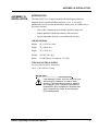
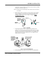
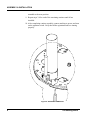
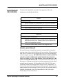
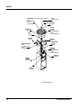
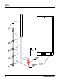
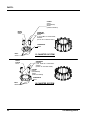
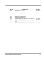
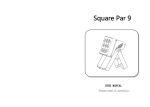
®
®
HARBIL
NSC50
Compact Colorant
Dispenser
Operating and
Instruction
Manual
Part # - 4700220
Rev. E
06/07/01
CONFIDENTIAL
PROPERTY OF FLUID MANAGEMENT®
(C) COPYRIGHT 2001 FLUID MANAGEMENT
AS AN UNPUBLISHED WORK ALL RIGHTS RESERVED
This material cannot be copied or disclosed to others without
the prior written permission of Fluid Management.
FLUID MANAGEMENT
A Unit of IDEX, Corp.
1023 Wheeling Road
Wheeling, Illinois 60090-5776
Voice
(847) 537-0880
US
(800) 462-2466
Fax
(847) 537-5530
www.fluidman.com
TABLE OF CONTENTS
Table Of Contents
ASSEMBLY & INSTALLATION - - - - - - - - - - - - - - - - - - - - - - -5
ASSEMBLY & INSTALLATION - - - - - - - - - - - - - - - - - - - - - - -6
BASIC OPERATION - - - - - - - - - - - - - - - - - - - - - - - - - - - - - - 12
MAINTENANCE PROCEDURES - - - - - - - - - - - - - - - - - - - - - 13
PARTS: - - - - - - - - - - - - - - - - - - - - - - - - - - - - - - - - - - - - - - - - 14
NSC50 Operating & Instruction Manual
3
4
Fluid Management ®
ASSEMBLY & INSTALLATION
ASSEMBLY &
INSTALLATION
INTRODUCTION
The Harbil NSC50 is a compact manual colorant dispenser that was
designed for exceptional reliability and ease of use. It is a nearly
maintenance free device that should deliver many years of reliable service.
Its features include:
•
Heavy-duty components and a durable finish for long wear.
•
Botton agatation linked with rotation of the canisters.
•
Special adjustable shelving to accomidate all can sizes.
SPECIFICATIONS
Height
60" (152.4 cm.) Max
Width
24" (609.6 cm.)
Depth
30" (762.0 cm.)
Weight
195 lbs" (88.5 kg.)
Motor
1/6 HP (Draws 3.0 Amps @ 115 VAC)
TYPICAL ELECTRICAL SUPPLY
See name plate for specific information.
120 V ± 10%, 60 Hz 15 Amp
IMPORTANT:
If any damage is found, notify the carrier at once
and arrange for inspection in order to claim
recovery. Claims for damage must be made by
the consignee (YOU).The carrier assumes full
responsibility upon acceptance of shipment and
will not entertain any claims by the consignor
(Fluid Management).
NSC50 Operating & Instruction Manual
5
ASSEMBLY & INSTALLATION
ASSEMBLY &
INSTALLATION
MOUNTING THE CANISTERS
The Harbil NSC80 requires only the simple fastening of the individual
canisters to the turntable. The canisters must be mounted in the proper order.
Do not fill the canisters before that are mounted.
It is critical that the crank be captured by the bushings that are part of the
star wheel assembly. For machine configurations containing less than 12
canisters, hole plugs are provided (FM P/N 25956) to cover the unused
canister positions.
1. Unplug the machine before installing canisters.
2. The drive star rotates freely around the drive cam mechanism under the
turntable. Rotate drive star with fingers (or other object) inserted through
the large holes. Rotate until all of the nylon drive star bushings are
visible through all of the large holes. (See Figure 1)
BUSHING
NOT
SHOWING
ALL
BUSHINGS
VISIBLE
CORRECT
NOT
CORRECT
Figure 1 BUSHING ALIGNMENT
3. Insert two screws into the threaded holes on bottom of the canister.
Allow about 1/8”-1/4” of thread (3-5 threads) to be exposed, as shown in
Figure 2 on page 7.
4. Align the screw heads with the button holes on the turntable for the front
canister position and rotate the agitation blade until the agitation crank is
aligned with the nylon bushing. (Figure 3 on page 7)
5. Lower the canister into position, assuring that the agitation crank is
captured by the nylon bushing and that the screw heads pass through the
6
Fluid Management ®
ASSEMBLY & INSTALLATION
button holes, as shown in figure 3-A. Rotate canister clockwise locking
it into place as shown in Figure 3-B.
NOTE: The dispense port will fall through its hole, and the canister will sit flat on
the turntable.
6. While holding canister in position, secure the canister to the turntable
using a screwdriver. Access holes are provided at the bottom of the
turntable to tighten the two screws. (Figure 4 on page 8) Do not
overtighten these screws.
CANISTER
1/4”- 20
CANISTER
MOUNTING
HOLES
AGITATION
CRANK
1/8”- 1/4”
1/8 to 1/4
BOTTOM
VIEW
Figure 2 CANISTER
7. Verify that the agitation crank is engaged by the nylon drive star
bushing. This is done by turning the agitation blade inside the canister.
Resistance to turning indicates that the agitation rod is engaged. If the
agitation blade turns freely, the agitation rod is not engaged and the
canister must be re-mounted.
IF AGITATION
BLADE MOVES
BY HAND, THE
CRANK IS NOT
CAPTURED BY
BUSHING.
ROTATE CLOCK-WISE
TO LOCK CANISTER
INTO PLACE.
(A )
(B)
BUTTON
HOLE
Figure 3 BUTTON HOLE MOUNTING
8. After installing the first canister, lower the index lever and rotate the
NSC50 Operating & Instruction Manual
7
ASSEMBLY & INSTALLATION
turntable to the next position.
9. Repeat steps 3-6 for each of the remaining canisters until all are
installed.
10. After completing canister assembly, connect machine to power, and turn
on the agitation switch. Verify that all the agitation blades are turning
properly.
Figure 4 SECURING CANISTER
8
Fluid Management ®
ASSEMBLY & INSTALLATION
CONNECTING TO THE POWER SOURCE
GROUNDING
In the event of an electrical short circuit, grounding reduces the risk of
electrical shock by providing an escape wire for the electric current. The 3prong plug, equipped with grounding wire, must be plugged into a 3-slot
receptacle that is properly installed and grounded in accordance with all
local codes and ordinances.
DANGER:
Improper use of the grounding plug can
result in a risk of electric shock.
GROUNDED
OUTLET
GROUNDING
PIN
Figure 5 Grounding Methods
DO NOT connect the grounding wire to a flat-blade terminal. The wire with
the insulation having an outer surface that is green (with or without yellow
stripes) is the grounding wire.
Check with a qualified electrician or serviceman if you are not sure how to
ground this machine. Under no circumstances should you modify the
plug if it does not fit the outlet.
WARNING:
After you have plugged the unit into a
dedicated power line and leveled it, inspect
to be sure that you have removed the
shipping materials.
NSC50 Operating & Instruction Manual
9
ASSEMBLY & INSTALLATION
Connect the 115 volt models only to a 115 volt outlet rated at at least 15
ampere. Connect the 220 volt models only to a 220 volt outlet rated at at
least 15 ampere. The equipment requires a single, grounded outlet.
EXTENSION CORDS
Extension cords for 220 VAC models are not recommended. If an extension
cord is to be used, it should not be combined with others. Use only a 3-wire
extension cord that has a 3-pole grounding plug. Power should be provided
by a 3-pole receptacle that will accept the plug on the product. Make sure
that your extension cord is in good condition. It must have # 16 AWG
conductors up to 25 feet long. An extension cord 25 feet long, but no longer
than 50 feet is permissible provided it has conductors of at least # 12 AWG.
It must be heavy enough to carry the current your product will draw. An
undersized cord can cause a drop in line voltage resulting in loss of power,
overheating and damage to the motor.
Under no circumstances should you modify the plug if it does not fit the
outlet.
Check with a qualified electrician or serviceman if you are not sure how to
ground this machine.
10
DISTANCE
25
ft
50
ft
100
ft
150
ft
200
ft
250
ft
300
ft
400
ft
500
ft
GAUGE
SIZE
220V
14
14
12
10
10
8
8
6
6
GAUGE
SIZE
115V
14
12
8
6
6
4
4
2
2
Fluid Management ®
ASSEMBLY & INSTALLATION
FILLING CANISTERS
After all of the canisters have been installed on the turntable, they can be
filled. Each canister has a maximum capacity of 2-1/2 quarts. It is
recommended that each canister be filled with two (2) quarts of colorant.
The maximum capacity of the pump is two (2) ounces.
The following steps represent the process by which the canisters should be
filled:
1. Locate the first canister and determine which colorant is to be placed
into that canister.
2. Place the appropriate decal on the canister.
3. Shake of stir the colorant following manufacturers recommendations.
4. Slowly, pour the colorant into the canister to the level of approximately
two (2) quarts.
5. Place the top on the canister.
6. Repeat these steps for each of the remaining canisters.
7. After all of the canisters have been filled, agitate by turning on the
agitation motor. This will release any air trapped in the colorant.
PRIMING OF PUMPS
Once the canisters have been both filled and agitated, the pumps attached to
each of the canisters must be properly primed. Follow these steps to prime
the pumps.
1. Locate the first canister.
2. Slowly pull the pump handle all of the way to the top of its stroke and
wait in this position for a count of approximately three (3) seconds.
3. Slowly press the pump handle all of the way down to the bottom of its
stroke.
4. Repeat these steps five (5) times.
5. Repeat steps 1 through 4 for each of the remaining canisters.
NSC50 Operating & Instruction Manual
11
BASIC OPERATION
BASIC
OPERATION
This dispensing equipment is designed for ease of use. The following steps
represent the method by which a formula is to be dispensed:
1. Determine the formula of the color selected by the customer.
2. Refer to the formula book and select the proper base paint.
3. Remove the lid on the base paint.
4. Pull out the appropriate shelf and place the can of base paint on the shelf.
5. Press the indexing lever down and rotate the turntable to the position
indicated by the formula book.
6. Turn the pump gauge to center the indicator pointer.
7. Lift the pump handle up until the indicator is opposite the notch on the
gauge.
8. Turn the gauge into the notch that represents the desired amount of colorant per the formula book.
9. After the pump handle has been in this position for about three (3) seconds, slowly pull the valve lever down and hold in that position with the
left hand.
10. While holding the valve down with the left hand, turn the gauge to the
center of the indicator and slowly push the pump handle down all of the
way to the bottom of the stroke. This will dispense a metered amount of
colorant into the base paint. (Repeat this step as may be required by the
formula book.)
11. Referring to the formula book, Pull down the indexing lever and rotate
the turntable to the next position indicated and repeat these steps for
each of the colorants in the formula.
12. At this point in the process, the can of base paint has been tinted.
Remove the can, press the lid back on and mix appropriately.
12
Fluid Management ®
MAINTENANCE PROCEDURES
MAINTENANCE
PROCEDURES
To ensure safe, dependable operation of the equipment, follow the
maintenance schedule detailed below:
DAILY
Cleaning & Filling:
•
Agitate colorants every morning for five (5) to ten (10) minites.
•
Clean nozzles & outside cabinet surfaces with soap and water.
•
Check canisters and fill as required.
WEEKLY
Cleaning & Nozzle Maintenance:
•
Dispense a full measure of any colorant that has not been used
during the previous week. Dispense into a clean container and
return to the appropriate canister.
•
Clean all accessible inside surfaces with soap and water.
GENERAL MAINTENANCE
If a nozzle becomes clogged, the obstruction can generally be cleared by
inserting a paper clip or similar object in the valve opening. Before inserting
such a device, open the valve by pulling the valve lever down and holding
while clearing the opening. BE SURE THAT THE VALVE IS OPENED,
AND STAYS OPEN WHILE CLEANING IN THIS WAY. IF THE
VALVE CLOSES AT ANY TIME DURING THIS OPERATION, THE
VALVE COULD BE DAMAGED. If colorant leaks develop at the top of
the pump, or if colorant can be observed on the pump piston rod, the pump
assembly must be repaired. The Pump Repair Kit (P/N 4223212) can be
purchased from the Fluid Management Customer Service Department. A
colorant leak at the bottom of the pump assembly generally indicates that the
pump assembly has been damaged. In this case, the valve assembly must be
replaced with either the Viton Valve Repair Kit (P/N 4231002) or the
Thiokol Repair Kit (P/N 4231011).
NSC50 Operating & Instruction Manual
13
PARTS:
PARTS:
EQUIPMENT MAINTENANCE LOG
RECORD MODEL NUMBER HERE: _________________________
RECORD SERIAL NUMBER HERE: _________________________
SERVICE
DATE
14
DESCRIPTION & PARTS REPLACED
(STATE IF UNDER WARRANTY)
SERVICED
BY
Fluid Management ®
SPARE PARTS ORDER
Fluid Management Parts Order Form
Photocopy and use this form to
Mail or fax orders to:
1(800) 462-2466
Fluid Management A unit of IDEX | Phone:
1023 Wheeling Road
| Fax:
1(847) 537-5530
Wheeling, IL 60090
|
|
Sold To:
Ship To:
_____________________
_____________________
_____________________
_____________________
____________________
____________________
____________________
____________________
Purchase Order Number_________________
Ship Via: ______________________
Collect
Prepaid
QUANTITY
Taxable
PART
NUMBER
Comments:
Tax Exempt (Fax copy of exemption certificate.)
DESCRIPTION
_____________________________________
_____________________________________
_____________________________________
_____________________________________
________
UNIT
PRICE
______________
Date:
_________________________________________________
Signature
NSC50 Operating & Instruction Manual
15
PARTS:
TURNTABLE (12 CANISTER SHOWN) CAP
25318
F0060T13XR
(16 CANISTER)
NUT
25033
07046
WASHER
(12 CANISTER)
25249
BUSHING
24039
DRIVE
PLATE
CAM
25317
25219
(16 CANISTER)
25032
SPACERS
(12 CANISTER)
25224
WHEEL
25222
CIRCLE SHEAR
25316
(16 CANISTER)
25030
(12 CANISTER)
MOUNTING
PLATE
25225
MOTOR
8100001
SWITCH
4000033
LEVER
SPRING
4110906
SHELF
4110909
COUNTER TOP MODELS
16
Fluid Management ®
PART NO
DESCRIPTION
NO REQ
07046
5/8”-11 NUT
1
24039
BUSHING
25030
CIRCLE SHEAR (12 CANISTER UNITS ONLY)
1
25032
DRIVE PLATE (12 CANISTER UNITS ONLY)
1
25033
CIRCLE SHEAR (12 CANISTER UNITS ONLY)
1
25219
CAM ASSY
1
1 PER CANISTER
25222
WHEEL
5
25224
SPACER
10
25225
MOTOR MOUNTING PLATE
1
25249
5/8” FLAT WASHER
1
25318
TURNTABLE (16 CANISTER UNITS ONLY)
1
4000033
POWER SWITCH
1
4110906
LEVER SPRING
1
4110909
SHELF
1
8100001
DRIVE MOTOR
1
CAP
1
F0030T13XR
NSC50 Operating & Instruction Manual
17
PARTS:
CAP
TURNTABLE (12 CANISTER SHOWN)
F0060T13XR
25318
(16 CANISTER)
NUT
25033
07046
WASHER
(12 CANISTER)
25249
BUSHING
24039
CAM
25219
WHEEL
25222
CIRCLE SHEAR
25316
(16 CANISTER)
25030
(12 CANISTER)
DRIVE
PLATE
25317
(16 CANISTER)
25032
(12 CANISTER)
SPACER
25224
MOUNTING
PLATE
25225
MOTOR
8100001
(120VAC/60HZ)
23252
(220VAC/50HZ)
SWITCH
4000033
LEVER
SPRING
4110906
KNOB
4000008
FLOOR MODELS
18
Fluid Management ®
PART NO
DESCRIPTION
NO REQ
07046
5/8”-11 NUT
1
23252
DRIVE MOTOR
(220VAC/50HZ UNITS ONLY)
1
24039
BUSHING
25030
CIRCLE SHEAR (12 CANISTER UNITS ONLY)
1
25032
DRIVE PLATE (12 CANISTER UNITS ONLY)
1
25033
TURNTABLE (12 CANISTER UNITS ONLY)
1
25219
CAM
1
25222
WHEEL
5
25224
SPACER
10
25225
MOTOR MOUNTING PLATE
1
25249
5/8” FLAT WASHER
1
25316
CIRCLE SHEAR (16 CANISTER UNITS ONLY)
1
25318
TURNTABLE (16 CANISTER UNITS ONLY)
1
1 PER CANISTER
4000008
BLACK
1
4000033
POWER SWITCH
1
4110906
LEVER SPRING
1
8100001
DRIVE MOTOR
(120VAC/60HZ UNITS ONLY)
1
CAP
1
F0060T13XR
NSC50 Operating & Instruction Manual
19
PARTS:
PIN
8101106
CRANK
SHAFT
24383
AGITATION
BLADE
23243
20
CANISTER
4215000
(FOR 1 OZ. PUMP)
4215011
(FOR 2 OZ. PUMP)
Fluid Management ®
PART NO
DESCRIPTION
NO REQ
23243
AGITATION BLADE
1 PER CANISTER
24383
CRANK SHAFT
1 PER CANISTER
24831
TUBE (NOT SHOWN)
1 PER CANISTER
423100
VITON VALVE ASSY (NOT SHOWN)
1 PER CANISTER
4215000
CANISTER CANISTER 50 OZ. (FOR 1 OZ. PUMP)
4215011
CANISTER CANISTER 50 OZ. (FOR 2 OZ. PUMP)
1 PER STATION
1 PER STATION
4221100
PUMP TUBE AND PISTON (NOT SHOWN)
1 PER CANISTER
4228102
PUMP CAP INDICATOR (NOT SHOWN)
1 PER CANISTER
4231070
THIOKOL VALVE ASSY (NOT SHOWN)
1 PER CANISTER
8101106
PIN
1 PER CANISTER
8100311
TUBE BUSHING (NOT SHOWN)
1 PER CANISTER
NSC50 Operating & Instruction Manual
21
PARTS:
COVER
23244
(STANDARD)
24584
(FOR SOLVENTS)
DRIVE
PLATE
25032
CANISTER
ASSEMBLY
25428
(1-OZ. PUMP W / VITON SEAL
4305004
(10-OZ. W / THIOKOL SEAL)
TURNTABLE
25033
BOLT
02494
DRIVE
PLATE
25317
12 CANISTER SYSTEM
CANISTER
ASSEMBLY
4305004
(1-OZ. PUMP W / VITON SEAL
4305011
(20-OZ. W / THIOKOL SEAL)
COVER
23244
(STANDARD)
24584
(FOR SOLVENTS)
TURNTABLE
25318
BOLT
02494
22
16 CANISTER SYSTEM
Fluid Management ®
PART NO
DESCRIPTION
NO REQ
02494
MOUNTING BOLT, 14 X 20 X 1/2”
2 PER CANISTER
23244
CANISTER COVER (STANDARD)
1 PER CANISTER
24584
CANISTER COVER (FOR SOLVENTS)
1 PER CANISTER
25032
DRIVE PLATE (12 CANISTER UNITS)
1
25033
TURNTABLE (12 CANISTER UNITS)
1
25317
DRIVE PLATE (16 CANISTER UNITS)
1
25318
TURNTABLE (16 CANISTER UNITS)
1
25428
CANISTER ASSEMBLY (INCLUDES PUMP & 1 OZ. PUMP VALVE)
4000108
NOZZLE CAP W / PAD (NOT SHOWN)
4305004
CANISTER ASSY (INCLUDES PUMP, 1-OZ. THIOKOL SEAL PUMP
VALVE)
4305011
CANISTER ASSEMBLY (INCLUDES PUMP & 2 OZ. PUMP VALVE)
NSC50 Operating & Instruction Manual
1 PER STATION
1 PER CANISTER
1 PER STATION
23
Part No. 4700220
Rev. E
06/07/01
Fluid Management
1023 Wheeling Road
Wheeling, Illinois 60090-5773
Telephone: (847) 537-0880
1-800-462-2466
Fax (847) 537-5530
www.fluidman.com
Part No. 4700220
Rev. E
06/07/01