1
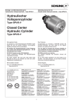
User’s Manual Model TUS400G Ultrasonic Oscillator IM 19C1B4-01E R IIM 19C1B4-01E 6th Edition i <INTRODUCTION> INTRODUCTION This user’s manual describes instructions for handling of the TUS400G ultrasonic oscillator, including procedures for installation, operation, inspection and maintenance. Also, information necessary for you to further understand the product is described as required. For handling of an ultrasonic vibrator for use together with this apparatus, refer to the user’s manual attached to the instrument with the ultrasonic vibrator built in. Model TB750G Title Right Angle Scatterde Kight TUrbidimeter IM No. IM 12E01A06-01E In continuous turbidity measurement, pollutive components sticking to the sensor of a turbidity meter is one of the causes of inaccurate measuring results. Therefore, cleaning of the sensor is an indispensable maintenance item for a lot of turbidity meters. Ultrasonic cleaning is one of methods for cleaning sensors. The major strong point of ultrasonic cleaning is that you can continuously perform it while making measurement. Ultrasonic cleaning has cleaning effect on most of pollutive components. The TUS400G ultrasonic oscillator is an apparatus for supplying an ultrasonic vibrator, built in a turbidity detector, with high-frequency energy. Below is the description of what you should do before use of the apparatus and what you should understand before reading this instruction manual. Specification Check Unpack your ultrasonic oscillator with care, and check for any damage that may be caused during transport. The TUS400G ultrasonic oscillator is fabricated to the customer specifications. For precautionary purposes, check to see that your ultrasonic oscillator is in accordance with your specifications, and that there is no missing accessory. Use the model codes indicated on the nameplate to check the specifications of your ultrasonic oscillators. For the meaning of the model codes, refer to Section 1.2. TUS400G -NN-NN-1-L1-J Location of Nameplate: Panel inside apparatus. Example on Indication of Nameplate Precautions Which Must Be Taken when Actuating TUS400G Ultrasonic Oscillator during Inspection NOTE When actuating the TUS400G ultrasonic oscillator, be sure to connect the ultrasonic vibrator (under load, that is, immersed in fluid) as under normal operating conditions. Operating the ultrasonic oscillator solely (or, with the ultrasonic vibrator under no load connected) may cause some electric parts to be abnormally heated. This is unfavorable in terms of the life of the ultrasonic oscillator. Media No. IM 19C1B4-01E 6th Edition : May. 2015 (YK) All Rights Reserved Copyright © 1996, Yokogawa Electric Corporation IM 19C1B4-01E ii <INTRODUCTION> For the safe use of this equipment n Safety, Protection, and Modification of the Product • In order to protect the system controlled by the product and the product itself and ensure safe operation, observe the safety precautions described in this user’s manual. We assume no liability for safety if users fail to observe these instructions when operating the product. • If this instrument is used in a manner not specified in this user’s manual, the protection provided by this instrument may be impaired. • Be sure to use the spare parts approved by Yokogawa Electric Corporation (hereafter simply referred to as YOKOGAWA) when replacing parts or consumables. • Modification of the product is strictly prohibited. • The following symbols are used in the product and user’s manual to indicate that there are precautions for safety: n Notes on Handling User’s Manuals • Please hand over the user’s manuals to your end users so that they can keep the user’s manuals on hand for convenient reference. • Please read the information thoroughly before using the product. • The purpose of these user’s manuals is not to warrant that the product is well suited to any particular purpose but rather to describe the functional details of the product. • No part of the user’s manuals may be transferred or reproduced without prior written consent from YOKOGAWA. • YOKOGAWA reserves the right to make improvements in the user’s manuals and product at any time, without notice or obligation. • If you have any questions, or you find mistakes or omissions in the user’s manuals, please contact our sales representative or your local distributor. n Warning and Disclaimer The product is provided on an “as is” basis. YOKOGAWA shall have neither liability nor responsibility to any person or entity with respect to any direct or indirect loss or damage arising from using the product or any defect of the product that YOKOGAWA can not predict in advance. IM 19C1B4-01E iii <INTRODUCTION> n Symbol Marks Throughout this user’s manual, you will find several different types of symbols are used to identify different sections of text. This section describes these icons. WARNING Indicates a potentially hazardous situation which, if not avoided, could result in death or serious injury. CAUTION Indicates a potentially hazardous situation which, if not avoided, may result in minor or moderate injury. It may also be used to alert against unsafe practices. IMPORTANT Indicates that operating the hardware or software in this manner may damage it or lead to system failure. NOTE Draws attention to information essential for understanding the operation and features. IM 19C1B4-01E iv <INTRODUCTION> After-sales Warranty n Do not modify the product. n During the warranty period, for repair under warranty consult the local sales representative or service office. Yokogawa will replace or repair any damaged parts. Before consulting for repair under warranty, provide us with the model name and serial number and a description of the problem. Any diagrams or data explaining the problem would also be appreciated. l If we replace the product with a new one, we won’t provide you with a repair report. l Yokogawa warrants the product for the period stated in the pre-purchase quotation Yokogawa shall conduct defined warranty service based on its standard. When the customer site is located outside of the service area, a fee for dispatching the maintenance engineer will be charged to the customer. n In the following cases, customer will be charged repair fee regardless of war- ranty period. • Failure of components which are out of scope of warranty stated in instruction manual. • Failure caused by usage of software, hardware or auxiliary equipment, which Yokogawa Electric did not supply. • Failure due to improper or insufficient maintenance by user. • Failure due to modification, misuse or outside-of-specifications operation which Yokogawa does not authorize. • Failure due to power supply (voltage, frequency) being outside specifications or abnormal. • Failure caused by any usage out of scope of recommended usage. • Any damage from fire, earthquake, storms and floods, lightning, disturbances, riots, warfare, radiation and other natural changes. n Yokogawa does not warrant conformance with the specific application at the user site. Yokogawa will not bear direct/indirect responsibility for damage due to a specific application. n Yokogawa Electric will not bear responsibility when the user configures the product into systems or resells the product. n Maintenance service and supplying repair parts will be covered for five years after the production ends. For repair for this product, please contact the nearest sales office described in this instruction manual. IM 19C1B4-01E v <CONTENTS> Model TUS400G Ultrasonic Oscillator IM 19C1B4-01E 6th Edition CONTENTS INTRODUCTION....................................................................................................i For the safe use of this equipment....................................................................ii After-sales Warranty...........................................................................................iv 1. 2. Overview..................................................................................................... 1-1 1.1 Standard Specifications.................................................................................... 1-1 1.2 Model and Suffix Codes.................................................................................... 1-3 1.3 External Dimensions......................................................................................... 1-4 Installation and Wiring.............................................................................. 2-1 2.1Installation.......................................................................................................... 2-1 2.2 3. Installation Site.................................................................................... 2-1 2.1.2 Installing Procedure............................................................................ 2-2 Wiring.................................................................................................................. 2-4 2.2.1 Types of Wiring................................................................................... 2-4 2.2.2 Cable Protection by Conduit............................................................... 2-4 2.2.3 Connecting Ultrasonic Vibrator Cable................................................ 2-5 2.2.4 Power Supply Wiring .......................................................................... 2-5 2.2.5 Ground Wiring .................................................................................... 2-5 Operation.................................................................................................... 3-1 3.1 Names and Function of Each Part................................................................... 3-1 3.2 Preparation for Operation................................................................................. 3-1 3.3 4. 2.1.1 3.2.1 Inspecting State of Wiring Installation................................................. 3-1 3.2.2 Adjusting Ultrasonic Power................................................................. 3-2 Steady State Operation..................................................................................... 3-3 3.3.1 Checking Influence of Ultrasonic Wave Application on Measured Turbidity Value... 3-3 3.3.2 If In-Action Pilot Lamp Goes OFF (Related information: Section 4.2)..... 3-3 3.3.3 Stopping and Restarting Operation.................................................... 3-4 Inspection and Maintenance.................................................................... 4-1 4.1 4.2 Inspecting State of Ultrasonic Wave Application........................................... 4-1 4.1.1 Checking State of Ultrasonic Oscillator Operation ............................ 4-1 4.1.2 Checking Degree of Influence on Measured Value............................ 4-1 Inspection When In-Action Pilot Lamp is OFF............................................... 4-2 4.2.1 How to Find Cause of Pilot Lamp Going Out...................................... 4-2 4.2.2 Replacing Procedure for Fuse............................................................ 4-3 IM 19C1B4-01E vi <CONTENTS> 5. Troubleshooting........................................................................................ 5-1 5.1 Remedies for Troubles...................................................................................... 5-1 5.1.1 Troubles and Possible Causes........................................................... 5-1 5.1.2 Remedy for Supply Voltage Drop....................................................... 5-1 5.1.3 Remedy for failure in the ultrasonic oscillator or defect in the ultrasonic vibrator... 5-1 5.1.4 Remedy for disconnection of the connecting cable for the ultrasonic transducer.. 5-1 Customer Maintenance Parts List.......................................CMPL 19C01B04-01E Revision Information................................................................................................i IM 19C1B4-01E 1. 1-1 < 1. Overview > Overview The TUS400G ultrasonic oscillator is an apparatus that composes an ultrasonic cleaner together with an ultrasonic piezoelectric transducer (vibrator). The TUS400G supplies the ultrasonic vibrator with operating power via a cable. The ultrasonic vibrator to be combined with the TUS400G is a vibrator mode of lead zirconate-titanatebased piezoelectric ceramics. The ultrasonic vibrator is built in the turbidity detector. TUS400G Ultrasonic oscillator TB750G Turbidity detector Ultrasonic vibrator Power supply cable for TUS400G Ultrasonic vibrator cable Figure 1.1 Configuration of Ultrasonic Cleaner Using TUS400G Ultrasonic Oscillator This chapter gives the description of the specifications for the TUS400G ultrasonic oscillator. 1.1 Standard Specifications Combination device: Turbidimeter (TB750G) Special cable (3-conductor shielded cable) Cleaning method: Continuous ultrasonic emission (Frequency sweep method) Oscillation frequency: Approx. 170 to 200 kHz (sweeping frequency: Approx. 160 to 250 kHz) Output voltage: Approx. 40 to 80 V Note: 1. Output of ultrasonic oscillator changes with power supply voltage. The output is lower when the voltage is lower. 2. Output of ultrasonic oscillator changes with connected cable. The output is lower when the length of the cable is longer. Power supply: 100/110/115/200/220/240 V AC±10% 50/60 Hz Power consumption: Approx. 30 VA Insulation resistance: Power supply-G: 100 MΩ or more / 500 V DC Output terminals-G: 100 MΩ or more / 500 V DC Withstand voltage: Power supply-G: 1000/1500 V AC for 1 min. Output terminals-C: 1000/1500 V AC for 1 min. Ambient Temperature: -10 to 50°C (hood may be fitting as option) Storage Temperature: -25 to 70°C Construction: JIS C0920 Watertight (NEMA 4 equivalent waterproof construction) Material: Finish: Case; Aluminum alloy casting Window;Polycarbonate Baked polyurethane resin (Standard) Baked epoxy resin (Option) IM 19C1B4-01E 1-2 < 1. Overview > Color: Case; Frosty white (Munsell 2.5Y8.4/1.2 or equivalent) Cover; Deep sea-moss green (Munsell 0.6GY3.1/2.0 equivalent) Mounting: Pipe mounting, wall or rack mounting or panel mounting Mounting material: Stainless steel Cable inlet port: Ø22.7 hole x 2 DIN Pg16 watertight plastic gland Cable/terminal: For 7 to 12 mm, M4 screw Conduit adapter: Power supply side (optional) Material: Polycarbonate resin Connection: G1/2 or 1/2NPT Weight: Body: Approx. 2.0 kg Mounting: Approx. 0.7 kg Dimension: 162W x 180H x 115D mm Noise filter assembly: (for TUS400G-NN-RC, TUS400G-NN-KC) Ambient temperature: -10 to 50°C (no dew condensation allowed) Strage temperature: -25 to 70°C Construction: JIS C 0920 Watertight (IP53) Regulatory Compliance (for TUS400G-NN-RC) EMC Regulatory Arrangement in Australia and New Zealand EN 55011 Class A, Group 1 (for TUS400G-NN-KC) Korea Electromagnetic Conformity Standard Class A 한국 전자파적합성 기준 A급 기기 (업무용 방송통신기자재) 이 기기는 업무용(A급) 전자파적합기기로서 판매자 또는 사용자는 이 점을 주의하시기 바라며, 가정외의 지역에서 사용하는 것을 목적으로 합니다. IM 19C1B4-01E 1.2 1-3 < 1. Overview > Model and Suffix Codes Model TUS400G — Application Suffix Code Option Code ............................................ -NN -NN -RC -KC Supply voltage *2 -1 -2 -3 -4 -5 -6 -00 Ultrasonic vibrator connecting cable -L1 -L2 -L3 -L4 -05 -10 -15 Language for directions -E Option *1: *2: Description ....................... ....................... ....................... ....................... ....................... ....................... ....................... ....................... ....................... ....................... ....................... ....................... ....................... ....................... ....................... ....................... ....................... ....................... ....................... ....................... Ultrasonic oscillator for turbidimeter Always -NN General Australia, for Oceania areas For Korea 100 V AC, 50/60 Hz 110 V AC, 50/60 Hz 115 V AC, 50/60 Hz 200 V AC, 50/60 Hz 220 V AC, 50/60 Hz 240 V AC, 50/60 Hz None 1 m (for Model TB700G or TB750G) 5 m (for Model TB700G or TB750G) 10 m (for Model TB700G or TB750G) 15 m (for Model TB700G or TB750G) 5 m (for Model 8562) 10 m (for Model 8562) 15 m (for Model 8562) Japanese (Directions indicated on product: Some are written both in Japanese and in English.) -J ....................... English (Directions indicated on product: Some are written both in Japanese and in English.) Mounting hardware /PS Pipe mounting (SUS) /W Wall mounting (SUS) /PA Panel mounting (SUS) Hood /H Sunshade hood Tag plate /SCT Stainless steel tag plate Special painting /X1 Epoxy painting Adapter for /AFTG G1/2 conduit work /ANSI 1/2NPT Special screwsr /SPS Teflon coated SUS steel screws (resistant to salt corrosion) *1 The SUS screws with Teflon coating are used at the four corners of the cover. The power supply to TB700G or TB750G should be determined in accordance with the supply voltage specified here. Accessories Part Name Spare Fuse Part Number K9317AZ Remarks 1 A : 1 pc, 2 A : 2 pcs IM 19C1B4-01E 1-4 < 1. Overview > 1.3 External Dimensions 202 Unit : mm 155 162 48 50 115 96 68 30 180 130 Hood (optional) 42 Ground terminal : M4 screw 56 Power supply cable inlet port with cable gland (Pg16 or equivalent) 2-M5 screws (for mounting bracket) Ultrasonic transducer cable inlet port, with cable gland (Pg16 or equivalent) Weight : Approx. 2.0 kg Ultrasonic Vibrator Connecting Cable (Note) Not attached when suffix code “-00” is specified. Turbidimeter side U1 U2 U3 Ultrasonic oscillator side S U1 U2 U3 60±5 Ø9 L (Cable length) A Unit : mm L (Approx.) A (Approx.) Combination device Model Code TUS400G - NN - NN - -L1 - 1 m TB750G TUS400G - NN - NN - -L2 - 5 m 180 or TB700G TUS400G - NN - NN - -L3 - 10 m TUS400G - NN - NN - -L4 - 15 m TUS400G - NN - NN - -05 - 5 m 80 8562 TUS400G - NN - NN - -10 - 10 m TUS400G - NN - NN - -15 - 15 m Conduit connecting adapter (option code: /AFTG, /ANSI) Cable gland Adapter Unit : mm Approx. 55 Case Packing 49 Nut G1/2 female ( / AFTG) 1/2NPT female ( / ANSI) IM 19C1B4-01E < 1. Overview > 1-5 Pipe Mounting Bracket (option code: /PS) 155 48 2-Ø5.5 holes (for hood) 27 110 8 50 115 Unit : mm 100 70±0.2 56±0.2 30 2-inch (OD Ø60.5) pipe(vertical mounting) 151 288 203 2-inch (OD Ø60.5) pipe(horizontal mounting) 2-Ø6.6 holes (for oscillator) 48 Weight: Approx. 0.7 kg Panel Mounting Bracket (option code: /PA) +1.1 156 0 121 38 80 3.9 185 205 121 2-M5 Screws Weight: Approx. 0.4 kg Unit : mm 138 173 0 138 60 30 +1.1 1 to10 (panel thickness) Panel mounting hardware Panel cutout dimensions Wall Mounting Bracket (option code: /W) 80 3.9 100 70±0.2 56±0.2 Unit : mm 27 13 185 3-Ø10 holes 27 2-Ø6.6 holes (for oscillator) 15 38 60 30 8 2-Ø5.5 holes (for hood) 70±0.2 Weight: Approx. 0.4 kg IM 19C1B4-01E 1-6 < 1. Overview > Noise filter assembly (for TUS400G-NN-RC, TUS400G-NN-KC) 275 10 Unit: mm 92 External power cable inlet (cable OD of Ø6 to Ø12) Dedicated power cable outlet 75 203 17 4-M5 screws, (depth:10mm) (for mounting) Dedicated power cable for noise filter assembly Black L1 White L2 Green G Approx. 80 36 Cable length : Approx. 0.7 m 70 152 Approx. 80 Weight of noise filter assembly: Approx. 2 kg Weight of power cable: Approx. 0.2 kg • Pipe Mounting Bracket for Noise filter assembly (option code: /PS) Unit: mm 8 4-M5 screws 70 5- Ø6.5 holes Ø6.5 x 13 hole 75 Pipe mounting bracket 1 200 2- Ø5.5 holes U-bolt 15 35 35 Pipe mounting bracket 2 2-Ø9 holes M8 nut ×2 70 100 4-Ø10 holes (10) Weight: Approx. 0.7 kg IM 19C1B4-01E (92) L1 Black L2 White G Green (54) 2-inch pipe (vertical mounting OD Ø60.5) < 1. Overview > • Wall or Panel Mounting Bracket for Noise filter assembly (option code: /W, /PA) 1-7 Unit: mm 8 4-M5 screw 70 5- Ø6.5 holes 75 Ø6.5 x13 hole 15 35 35 200 Wall mounting bracket 2- Ø5.5 holes 70 100 4- Ø10 holes (10) Weight: Approx. 0.7 kg 4-M6 screw (customer’s scope) (92) 13 IM 19C1B4-01E Blank Page 2. 2-1 < 2. Installation and Wiring > Installation and Wiring The TUS400G ultrasonic oscillator should be installed in a place where the power switch is easily turned ON/OFF and the “in-action” pilot lamp. Install the TUS400G as close to the turbidimeter as possible. This chapter describes how to select an installation site and procedures for installation and wiring. 2.1Installation The TUS400G ultrasonic oscillator may be installed outdoors. However, it should be installed in as favorable an environment as possible in order to keep its electric circuits in good condition. 2.1.1 Installation Site Install the TUS400G ultrasonic oscillator in a place where the following requirements are met: • The TUS400G must be installed as close to the location of the ultrasonic vibrator as possible. If a cable for connecting the ultrasonic oscillator and the ultrasonic vibrator is too long, an ultrasonic power required to obtain sufficient cleaning effect will not be obtained. Make sure that the length of the cable does not excessively exceed 15 meters. • The TUS400G must be installed in a place free from corrosive gases. Corrosive gases damage the electric parts in the oscillator and should be avoided. • The TUS400G must be installed in a place with less fluctuation in temperature at ordinary temperature or a temperature close to ordinary temperature. The fluctuation in temperature at the installation site should be within the range of -10 to 50°C. • The TUS400G must be installed in a place where a humidity of 5 to 90% HR is maintained. Avoid installing the ultrasonic oscillator in a place where a high or low humidity is maintained for a long time. It is recommended to always operate the TUS400G at a humidity of 25 to 85% RH. • The TUS400G must be installed in a place not exposed to direct sunlight. Direct sunlight may excessively increase temperature in the oscillator. If there is any high temperature equipment nearby, temperature in the oscillator may be also excessively increased due to radiant heat. If temperature in the oscillator is likely to rise and exceed allowable limit due to direct sunlight, then install a sunshade hood (optional) Figure 2.1 Sunshade as Installed IM 19C1B4-01E 2-2 < 2. Installation and Wiring > 2.1.2 Installing Procedure The ultrasonic oscillator may be mounted on panel, a wall surface or a pipe (2-inch, OD: 60.5 mm). Hardware corresponding to the type of mounting used is required to install the TUS400G. Mounting hardware is attached only when requested. In the case of TUS400G-NN-RC or TUS400G-NN-KC, a noise filter assembly is attached. Please refer to a figure of external dimensions for the attachment means of the noise filter assembly. (1) Panel Mounting Figure 2.2 illustrates the installing procedure for the ultrasonic oscillator using panel mounting bracket. Panel retaining screw Panel mounting bracket Panel Figure 2.2 Mounting Method for Ultrasonic Oscillator Using Panel Mounting Bracket To mount the TUS400G on a panel, cut out the panel in accordance with Figure 2.3. +1.1 0 Unit : mm 156 121 +1.1 0 173 138 138 121 Figure 2.3 IM 19C1B4-01E Panel Cutout Dimensions (2) 2-3 < 2. Installation and Wiring > Pipe Mounting When mounting the TUS400G on a pipe, install a pipe (2-inch, OD: 60.5 mm) in the vertical or horizontal direction. Figure 2.4 illustrates the installing procedure for the ultrasonic oscillator using pipe mounting bracket. Ultrasonic oscillator Pipe mounting bracket 2-inch pipe Figure 2.4 (3) Ultrasonic Oscillator as Mounted on Pipe Wall Mounting Figure 2.5 illustrates the installing procedure for the ultrasonic oscillator using wall mounting bracket. Drill screw holes (for M8 screw, 3 places) in accordance with the figure below before mounting the TUS400G. Retaining screw (2 pcs attached) Unit : mm Wall mounting bracket 70 ±0.2 27±0.2 M8 screw holes 3 pcs Mounting screw (M8 3 pcs, customer’s scope) Figure 2.5 Hardware and Procedure for Wall Mounting IM 19C1B4-01E 2-4 < 2. Installation and Wiring > 2.2 Wiring This section describes types of wiring installed for the TUS400G ultrasonic oscillator and wiring work procedures type by type. 2.2.1 Types of Wiring There are three types of wiring installed for the TUS400G ultrasonic oscillator. The ultrasonic vibrator cable (of a specified length) is attached only when requested. • Ultrasonic vibrator cable connection (power line for ultrasonic vibrator) • Power supply wiring • Grounding wiring Figure 2.6 illustrates the connecting terminals for these types of wiring. Turbidity detector Ultrasonic vibrator connecting cable (maximum length: 15 m) TUS400G uitrasonic oscillator U1 U1 U2 U2 U3 S Noise filter assembly * L1 L2 Note: Terminal U2 on the turbidity Dedicated power cable * detector is connected with two wires from Terminals Power Supply * For TUS400G-NN-RC, U2 and U3 on the ultrasonic TUS400G-NN-KC oscillator. Figure 2.6 Ground to earth (100Ω or less) External Wiring Diagram 2.2.2 Cable Protection by Conduit The power cable connected to the ultrasonic oscillator can be protected by conduits to prevent damage to its coating. In this case a dedicated cable gland with an adapter for conduit connection is required. The cable gland with an adapter is attached only when requested. [Mounting Procedure for Cable Gland with Conduit Connecting Adapter] Remove the cable gland (DIN Pg16 or equivalent) from the cable inlet in the ultrasonic oscillator, and install the attached cable gland (JIS 15A or equivalent) and the adapter for conduit connection, as shown in Figure 2.7. Firmly tighten the gasket to prevent moisture from entering the oscillator through the cable inlet. Adapter Unit : mm Approx. 55 Cable gland Packing 49 Nut Case G1/2 female ( / AFTG) 1/2NPT female ( / ANSI) Figure 2.7 IM 19C1B4-01E How to Install Adapter for Conduit Work 2-5 < 2. Installation and Wiring > 2.2.3 Connecting Ultrasonic Vibrator Cable The ultrasonic vibrator connecting cable is used to install the power wiring for the ultrasonic piezoelectric transducer (vibrator), which connects between Terminals U1, U2 and U3 on the TUS400G ultrasonic oscillator and Terminals UI and U2 on the turbidity detector. The ultrasonic vibrator connecting cable of a specified length (1 m, 5 m, 10 m or 15 m) is attached only when requested. If you fabricate an ultrasonic vibrator cable, then take the following points into account: [Precautions in Fabricating Ultrasonic Vibrator Connecting Cable (Power Cable for Vibrator)] • Use a three-core shielded cable with an outside diameter of 7 to 12 millimeters. The length of the cable must be limited to 15 meters or below. • Be sure to allocate the shield on the cable to “S”. Figure 2.8 illustrates the dimensions of the terminations of the power cable for vibrator. Turbidimeter detector side Ø7 to Ø12 mm U1 U2 U3 Approx. 180mm Figure 2.8 15 m or below Ultrasonic oscillator side To be soldered to sheild Approx. 60mm S U1 U2 U3 Cable Fabricating Procedure 2.2.4 Power Supply Wiring Use a two-core cable with a conductor nominal cross-sectional area of 0.5 mm2 or above for power supply wiring. Connect the cable from a power supply having a specified voltage (voltage fluctuation: within a range of ±10% of nominal voltage) to Terminal L1 and L2 on the ultrasonic vibrator. Note: If the supply voltage drops below the allowable range, the power of ultrasonic waves is weakened, which may result in the degradation in cleaning effect. The screw size of the terminals is M4. Use a crimp contact conformable to the size for cable termination. Place in the power supply wiring a switch for shutting off the power supply to the ultrasonic oscillator. With this switch provided, safety is ensured when the wires are removed from the ultrasonic oscillator for repair or the like. Use the power switch inside the TUS400G ultrasonic oscillator to start or stop it for or during steady state operation. In the case of TUS400G-NN-RC or TUS400G-NN-KC, please wire a noise filter assembly by all means. 2.2.5 Ground Wiring The TUS400G ultrasonic oscillator should be grounded to earth (grounding resistance: 100Ω or below). Use a conductor with a nominal cross-sectional area of 2 mm2 or above. The grounding terminal is located on the left side at the lower part of the case (when viewed from front) (Refer to the external dimensions on Sec. 1.3.) The terminal uses a M4 screw. IM 19C1B4-01E Blank Page 3. 3-1 < 4. Operation > Operation The TUS400G Ultrasonic Oscillator should be actuated when the turbidimeter is operated (when measurement fluid is started to flow). This chapter describes preparations before starting operation and operating procedures. 3.1 Names and Function of Each Part You can see the in-action pilot lamp through the window in the front cover. When you remove the front cover, you can find the power switch, fuses and so on. Front cover [WARNING] indication Caution against Electric Shock Some areas in the electric circuits in the panel remain carrying high voltage for a while even after the power switch is turned OFF. Never touch the electric circuits for 10 minutes after stopping power supply. Grounding terminal Be sure to ground the oscillator case. In-action pilot lamp (LED) Nameplate This LED is ON when the ultrasonic oscillator is properly operating. OUTPUT Sometimes this LED lights up during failure of the ultrasonic vibrator. Ultrasonic power adjuster Make adjustment so that the optimum ultrasonic power having no effect on measurements will be obtained. Suffix codes and the like representing the specifications for the TUS400G are indicated. FUSE 2A 1A 2A TERMINAL U1 U2 U3 S L1 L2 VOLUME Fuses These are fuses for the power input (L1: 1A, L2: 2A) and for the power circuit for the ultrasonic vibrator (U1: 2A). POWER ON OFF Power switch This switch should be turned ON/OFF according to the operation of the turbidimeter. Be sure to keep it OFF when the ultrasonic vibrator is NOT in contact with measurement fluid. External wiring terminals These are terminals to which the power supply wire and the ultrasonic vibrator cable are to be connected. Figure 3.1 3.2 Names and Function of Each Part in TUS400G Ultrasonic Oscillator Preparation for Operation Inspect the state of wiring installation before starting the steady state operation of the TUS400G ultrasonic oscillator. 3.2.1 Inspecting State of Wiring Installation Check to see that the wiring work has been properly executed to meet the following requirement: • The vibrator connecting cable must be properly connected to the right terminals on the ultrasonic oscillator and turbidity detector. The wires to be connected to Terminal U2 and U3 on the ultrasonic oscillator are connected together to Terminal U2 on the turbidity detector. The length of the cable must be 15 meters (approximately) or below. IM 19C1B4-01E 3-2 < 4. Operation > Note:If an existing two-core shielded cable is used, then check to see that Terminal U2 and U3 on the ultrasonic oscillator are short-circuited to each other. The shield on the cable should be connected to Terminal “S”. • A power supply of the specified voltage with voltage fluctuation within the allowable range must be available to Terminals L1 and L2 on the ultrasonic oscillator. For precautionary purposes, check to see that the fuses (three places) are firmly installed. NOTE With the ultrasonic vibrator unconnected, the in-action pilot lamp will not light up even if power is supplied. Do not operate the ultrasonic oscillator with the ultrasonic vibrator NOT in connect with fluid. Attention should be given especially when an existing two-core shielded cable is used. With the ultrasonic vibrator NOT in contact with fluid, some parts in the electric circuits are excessively heated to a temperature higher than in ordinary operation. This is unfavorable in terms of the life of the ultrasonic oscillator. • The ultrasonic oscillator must be grounded (grounding resistance: 100Ω or below.) 3.2.2 Adjusting Ultrasonic Power In ultrasonic cleaning, cavitation caused by the application of ultrasonic waves contributes to the cleaning effect. The more cavities are produced, the more the cleaning effect is enhanced. In turbidity measurement using an optical system, however, measured values are more largely influenced with increase in the number of cavities produced. Therefore, the ultrasonic power must be adjusted so that the influence on measurements is controlled to within an allowable range and that the cleaning effect is maximized. Use the VOLUME ultrasonic power adjuster located inside the ultrasonic oscillator to adjust the ultrasonic power. Take the following procedures in ultrasonic power adjustment: Note:To make the adjustment, the turbidimeter must be ready for operation. [Outline of Adjusting Operation] Fill the measuring cell (detector’s cell) in the turbidity detector with a measurement fluid. Operate the ultrasonic power adjuster until the difference becomes extinct (or falls within an allowable range) between the measured value when ultrasonic cleaning is NOT performed and that when it is under way. Note:Allowable difference range should be set case by case according to desired measuring accuracy. [Adjusting Procedure] (1) Fill the measuring cell in the turbidity detector with a measurement fluid at the same flow rate as in steady-state operation. Note: Even if the ultrasonic power is the same, the influence of ultrasonic waves on measured values varies depending on the properties (velocity of flow and amount of suspended solids) of fluid in the measuring cell. (2) Actuate the turbidimeter and record the value of an output signal using a reception meter. Note: The ultrasonic power adjuster should be operated while monitoring the record on the reception meter. If the ultrasonic oscillator is positioned far away from the tubidity meter, then place an apparatus equivalent to the tubidity meter close to the ultrasonic oscillator, and the adjusting operation is facilitated. (3) Turn the adjuster shaft of the ultrasonic power adjuster fully counterclockwise, and actuate the ultrasonic oscillator (turn ON the power switch inside the oscillator). Note: When the in-action pilot lamp lights, it indicates that the ultrasonic oscillator is normally operating. The ultrasonic oscillator gets to the required operating state in 10 minutes or so. IM 19C1B4-01E 3-3 < 4. Operation > (4) Adjust the irradiation intensity of ultrasonic waves. Carefully turn the adjusting shaft of the ultrasonic power adjuster clockwise to increase the irradiation intensity of ultrasonic waves while its influence on turbidity measurements is within the allowable range. After every 10-degree turn, check the value of the output signal. The influence of the ultrasonic waves can be checked with the record of the reception meter or the indications of the turbidity meter. After the adjustment is completed, turn off the power switch of the ultrasonic oscillator. Note: In general, increasing the flow rate of the measurement liquid minimizes the influence on measurements while the intensity of ultrasound waves remains strong. 3.3 Steady State Operation The ultrasonic oscillator should be operated only when the ultrasonic vibrator is in contact with fluid. If it is operated with the ultrasonic vibrator exposed to the air, or with no load (i.e. with the measuring cell empty), the temperature of the electric circuit parts excessively rises, which has harmful effect on the life of the ultrasonic oscillator. The TUS400G is provided with the function of stopping the power supply to the ultrasonic vibrator if the temperature of the electric circuit parts extraordinarily rises. If it is verified at the start of operation that favorable cleaning operation is in progress, it is unnecessary for the operator to control the ultrasonic oscillator during the subsequent steady state operation. When inspecting the turbidimeter, however, check to see that the in-action pilot lamp is ON 3.3.1 Checking Influence of Ultrasonic Wave Application on Measured Turbidity Value If the ultrasonic power is adjusted under conditions (properties of fluid and velocity of flow) different from those for steady state operation, check at the start of operation to see that the influence of that on the measured turbidity values is within the allowable range. To do this, take the following procedures: (1) Bring the turbidimeter and the output signal receiver in the state of steady state operation. For the operating procedure for these apparatuses, refer to the respective instruction manuals. (2) Actuate the ultrasonic oscillator: Turn ON the power switch inside the oscillator, and check to see that the in-action pilot lamp is ON. Further, check the glass window in the measuring cell in the turbidity detector for any sticking air bubble. If there is any sticking bubble, remove it referring to the instruction manual for the turbidimeter. (3) Allow the ultrasonic oscillator to operate for 10 minutes or so, and then turn OFF the power switch to stop the operation of the oscillator. Then examine change in output signal value. If the change is within the allowable range, turn ON the power switch in the ultrasonic oscillator again to start steady state operation. If the change is out of the allowable range, operate the ultrasonic power adjuster in accordance with the procedures described in Subsection 3.2.2. 3.3.2 If In-Action Pilot Lamp Goes OFF (Related information: Section 4.2) If the in-action pilot lamp goes off, the possible causes are: • A thermal protective element has been activated (extraordinary heating of electric circuit parts). [The oscillator case is giving off heat.] • Any fuse in the oscillator has burnt out. [The oscillator case is NOT giving off heat.] [In Case Thermal Protective Element Has Been Activated] The electric circuit parts extraordinarily heated have not completely dropped in temperature yet. Turn OFF the power switch located inside the ultrasonic oscillator first of all, and try to find the cause of the extraordinary heating. Do not turn ON the power switch again until the cause is removed. IM 19C1B4-01E 3-4 < 4. Operation > The possible causes of extraordinary heating of the electric circuit parts are: (1) Supply of measurement fluid is stopped, and the measuring cell becomes empty, and (2) Some trouble has occurred in the ultrasonic vibrator. If it turns out that the extraordinary heating was caused by the measuring cell becoming empty, take necessary measures to prevent the measuring cell from becoming empty during steady state operation. If it is found that the cause of the extraordinary heating was any trouble in the ultrasonic vibrator, the ultrasonic oscillator requires repair or replacement with a good one. Take necessary measures referring to “5. Troubleshooting” in this manual. When the cause of extraordinary heating is removed and temperature falls to a certain level, the thermal protective element is automatically reset (switch: ON). This lights up the in-action pilot lamp. [In Case Fuse Has Burnt Out] Replace the burnt fuse with a new one. (Refer to Subsection 4.2.2.) 3.3.3 Stopping and Restarting Operation For the prevention of trouble in the TUS400G ultrasonic oscillator and the ultrasonic vibrator, it is important to avoid operating it with no load (i.e. with the measuring cell empty). When performing maintenance work (zero point calibration, etc.) on the turbidimeter, turn OFF the power switch in the ultrasonic oscillator and then stop the supply of measurement fluid. To restart turbidity measuring operation, supply the measurement fluid and then turn ON the power switch in the ultrasonic oscillator . IM 19C1B4-01E 4. 4-1 < 4. Inspection and Maintenance > Inspection and Maintenance This chapter describes routine inspection and maintenance work required to allow the TUS400G ultrasonic oscillator to fully deliver its performance and to obtain favorable cleaning results. Refer to “5. Troubleshooting” in this manual for the improvements of the equipment preventing the achievement unfavorable cleaning effect and the remedies for troubles in the equipment. 4.1 Inspecting State of Ultrasonic Wave Application If ultrasonic wave application does not have sufficient cleaning effect, it is impossible to accomplish the purpose of ultrasonic cleaning of maintaining accurate turbidity measurement for a long time. Check whether the ultrasonic oscillator is normally operating whenever errors in measurements have been excessive due to ultrasonic wave application. 4.1.1 Checking State of Ultrasonic Oscillator Operation During turbidity measurement, check to see that the ultrasonic oscillator is satisfactorily operating as well. To do this, check whether the in-action pilot lamp inside the oscillator is ON. If not, perform maintenance work in accordance with the instructions described in Section 4.2. 4.1.2 Checking Degree of Influence on Measured Value Checks on the degree of the influence on the measured values are made mainly in the following cases: • When the flow rate (velocity of flow) of the measurement fluid largely departs from that at the time of ultrasonic power adjustment. • After the ultrasonic vibrator is replaced. This inspection is performed by comparing the measured value when ultrasonic wave are applied with those when there is no application. The measured values should be read in accordance with the procedures described in Subsection 3.3.l. If there is still large influence on the measured values after the adjustment of ultrasonic power, take other measures, such as increasing the flow rate of measurement fluid. IM 19C1B4-01E 4-2 < 4. Inspection and Maintenance > 4.2 Inspection When In-Action Pilot Lamp is OFF The in-action pilot lamp may be kept OFF by erroneous operation (e.g. forgetting to turn ON the power switch), or some trouble, such as anomalies in the wiring (disconnection and short circuit) and faults in the equipment. If the cause is such trouble, cope with it referring to Chapter 5. 4.2.1 How to Find Cause of Pilot Lamp Going Out Touch the case of the ultrasonic oscillator with your hand. [In Case Ultrasonic Oscillator Case is Giving Off Heat] Keep OFF the power switch in the oscillator until the cause is identified. If the case feels hot, the following are suspected to be the cause of the in-action pilot lamp going out: • The measuring cell in the turbidity detector has become empty (or was empty until just a few minute ago). Some of the electric parts in the ultrasonic oscillator extraordinarily increase in temperature if ultrasonic waves are applied from the ultrasonic vibrator with no load (with the measuring cell empty). This extraordinary temperature rise is detected by the thermal protective element, which then stops the power supply to the ultrasonic vibrator and turn OFF the in-action pilot lamp. Check whether fluid is flowing in the measuring cell. Or, check the record of measured turbidity values for any sign that the measuring cell has become empty. If it is revealed that the measuring cell in the turbidity detector became empty, for precautionary purposes, check whether there was any anomaly (e.g. cracking) in the fluid-contacting glass of the ultrasonic vibrator before the power supply to the vibrator is stopped (the thermal protective element is activated). When the measuring cell is filled with fluid and the temperature in the ultrasonic oscillator falls to the specified level, the in-action pilot lamp automatically lights up, and the power supply to the ultrasonic vibrator is restarted. Turn ON the power-switch and wait for a while (at most 30 minutes) until the equipment is brought to such a state. Note:If the measuring cell is spontaneously emptied of fluid during operation, it is required to improve the facilities (installed piping and so on). • The fuse has burnt out (in the power supply circuit for the ultrasonic vibrator). A 2A fuse is placed in the power circuit for the ultrasonic vibrator in the ultrasonic oscillator. Turn OFF the power switch and check whether the fuse has burnt out. Refer to Subsection 4.2.2 for details. • The power cable for ultrasonic vibrator is disconnected or short-circuited. The in-action pilot lamp goes out for the same reason as the case where the measuring cell becomes empty. First, check to see that the cable is connected to the terminals on the ultrasonic oscillator and turbidity detector with reliability. Next, check the cable for any disconnection or short circuit using a tester or the like. If the cable turns out to be faulty, cope with it in the instructions described in Subsection 5.2.1 in Chapter 5. • There is a problem in the ultrasonic vibrator. IM 19C1B4-01E If the pilot lamp going out is caused by neither of the three above-mentioned problems, the cause is often trouble in the ultrasonic vibrator. 4-3 < 4. Inspection and Maintenance > Referring to Subsection 5.2.2 in Chapter 5 in this manual or the instruction manual for the turbidimeter, examine the power supply circuit for the piezoelectric transducer (ultrasonic vibrator) in the turbidimeter. If the cause of the in-action pilot lamp going out cannot be identified even after checking all the above-mentioned items, contact YOKOGAWA. [In Case Ultrasonic Oscillator is NOT Giving Off Heat] If the case of the ultrasonic oscillator does not feel hot, the following are suspected to be the cause of the in-action pilot lamp going out. Check to see that power is supplied to the ultrasonic oscillator and the power switch in the oscillator is ON: • Any of the fuses has burnt out. The ultrasonic oscillator has two fuses, lA and 2A, in the power receiving circuit and a 2A fuse in the power circuit for the ultrasonic vibrator. Turn OFF the power switch and check whether any of the fuses has burnt out. Refer to Subsection 4.2.2 for details. • Failure in Electric Circuits If there is no problem in the fuses and yet the ultrasonic oscillator remains inactive, the cause is a problem in the electric circuits. Consults withYokogawa service. 4.2.2 Replacing Procedure for Fuse (Check to see that the power switch is OFF before proceeding with the procedure.) Using a flatblade screwdriver, remove the 1A fuse from the central one of the three fuse holders. If the fuse had burnt out, install the attached 1A fuse, and turn ON the power switch to actuate the ultrasonic oscillator. If the fuse has not burnt out, install it as it was. Then check the right-hand adjacent 2A fuse (in the power receiving circuit) and the left-hand adjacent 2A fuse (in the power circuit for the ultrasonic vibrator), similarly. IM 19C1B4-01E Blank Page 5. 5-1 < 5. Trouble shooting > Troubleshooting If ultrasonic cleaning yields unfavorable results, make inspections first of all, referring to Chapter 4 in this manual. This chapter describes remedies for malfunctions of the ultrasonic oscillator. Caution against Electric Shock Even after the power switch is turned off, do not touch the electric circuits in the TUS400G ultrasonic oscillator. Some parts continue to be at high voltage for a while. Consult Yokogawa for repairing the electric circuits. 5.1 Remedies for Troubles If any trouble is encountered, promptly try to find the cause and remedy it. 5.1.1 Troubles and Possible Causes Table 5.1 lists troubles that may be encountered and their causes. Table 5.1 Troubles and Causes Trouble No cleaning effect by ultrasonic radiation Frequent burnout of fuses In-action pilot lamp lighting does not come back Possible cause Drop in supply voltage (Refer to Subsection 5.1.2) Failure in the ultrasonic oscillator (Refer to Subsection 5.1.3) Defect in the ultrasonic vibrator (Refer to Subsection 5.1.3) Abnomaly in equipment (Refer to Subsection 5.1.3) Disconnection of the connecting wire for the ultrasonic vibrator (Refer to Subsection 5.1.4) Defect in the ultrasonic vibrator (Refer to Subsection 5.1.3) 5.1.2 Remedy for Supply Voltage Drop If the voltage of the power supply to the ultrasonic oscillator drops, the ultrasonic power is also reduced. If the voltage remains below the allowable range for a long time, re-connect the oscillator to another power supply with less voltage fluctuation. 5.1.3 Remedy for failure in the ultrasonic oscillator or defect in the ultrasonic vibrator Checking and repairing ultrasonic oscillators and vibrators require extensive expertise and skills with electric circuits. If the devices do not operate normally, have them serviced by Yokogawa engineers. 5.1.4 Remedy for disconnection of the connecting cable for the ultrasonic transducer Repair or replace the cable. IM 19C1B4-01E Blank Page Customer Maintenance Parts List TUS400G Ultrasonic Oscillator for Turbidimeter 5 4 1 3 2 Item Part No. Qty 1 K9317AJ K9317BJ 1 Description 3 Y9500WU 4 Washer 4 5 Y9102XA K9311JN 4 1 O-ring Window Assembly Cover Assembly (Coating : Baked polyurethane resin) (Coating : Baked epoxy resin) All Rights Reserved, Copyright © 1997, Yokogawa Electric Corporation. Subject to change without notice. Yokogawa Electric Corporation CMPL 19C01B04-01E 1st Edition : Feb. 1997 (YK) 4th Edition : Oct. 2007 (KP) 2 4 3 2 1 7 5 6 8 5 9 Item 1 2 3 Part No. K9317AB K9317EB K9317EP K9317EQ Qty 1 1 1 K9317ER K9317ES K9317ET K9317EU CMPL 19C01B04-01E Description Panel Assembly Timer Board Assembly Power Board Assembly (For 100 V AC Power Supply) (For 110 V AC Power Supply) (For 115 V AC Power Supply) (For 200 V AC Power Supply) (For 220 V AC Power Supply) (For 240 V AC Power Supply) 4 K9317AQ K9317BQ 1 Case Assembly (Coating : Baked polyurethane resin) (Coating : Baked epoxy resin) 5 6 7 8 A1111EF A1109EF L9811FK L9811FT 2 1 2 2 Fuse (2 A) Fuse (1 A) Nut Cable Gland 9 K9317AF K9317AG 1 Adapter Assembly (For G1/2 screw; option code : /AFTG) (For 1/2NPT screw; option code : /ANSI) All Rights Reserved, Copyright © 1997, Yokogawa Electric Corporation. 4th Edition : Oct. 2007 (KP) 3 CABLE ASSEMBLY (For TB700G, TB750G: Suffix code of -L1, -L2, -L3, or -L4) (For 8562 Terbidimeter: Suffix code of -05, -10, -15) SUNSHADE HOOD(Optional code : /H) 2 1 MOUNTING BRACKET 3 4 Option code : /PS Option code : /W 5 Option code : /PA Item 4th Edition : Oct. 2007 (KP) Part No. Qty Description 1 K9658PE K9658PF K9658PG K9658PH K9317AL K9317AM K9317AN 1 Cable Assembly (Cable length 1m, suffix code of -L1) (Cable length 5m, suffix code of -L2) (Cable length 10m, suffix code of -L3) (Cable length 15m, suffix code of -L4) (Cable length 5m, suffix code of -05) (Cable length 10m, suffix code of -10) (Cable length 15m, suffix code of -15) 2 3 4 5 K9311KG K99311KL K9149SB K9311KA 1 1 1 1 Sunshade Hood Pipe Mounting Bracket Wall Mounting Bracket Panel Mounting Bracket All Rights Reserved, Copyright © 1997, Yokogawa Electric Corporation. CMPL 19C01B04-01E i Revision Information : Model TUS400G Ultrasonic Oscillator Title Manual No. : IM 19C1B4-01E May 2015/6th Edition The reconsideration of contents, typographical errors corrected 3.2.2 The description in Outline of Adjusting Operation and Adjusting Procedure revised Chapter 5 Note on the symbol for electric shock revised 5.1.1 The description in Table 5.1 revised Subsections 5.1.3 and 5.1.4 added Subsection 5.2 deleted Mar. 2014/5th Edition Addition of "Australia, for Oceania areas (-RC)" and "For Korea (-KC)" 1.1 Addition of specifications, 1.2 Addition of Suffix Code, 1.3 Addition of the Noise filter assembly, 2.1.2 & 2.2.4 Postscript about -RC & -KC Jul. 2012/4th Edition Page layout changed by InDesign Revised and corrected all over (p.1-2, 8562 tubidimeter cables added to MS-code, p.1-3, 8562 tubidimeter cables added to external dimensions, etc.) Oct. 2007/3rd Edition IM style & Format renewed Revised and corrected all over (“After-Sales Warranty” added, CMPL 19C01B04-01E revised to 4th edition, etc.) Feb. 1997/2nd Edition Some error correction. Apr. 1996/1st Edition Newly published. n If you want to have more information about Yokogawa products, you can visit Yokogawa’s home page at the following web site. Home page: http://www.yokogawa.com/an IM 19C1B4-01E Blank Page