1
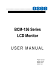
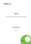
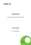
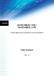
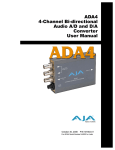
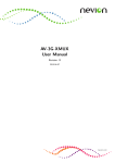
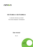
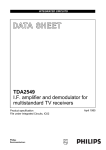
SPG-AVA-DMUX Sync-Pulse Generator/Replicator with Linear Time Code and AES reference outputs User manual Rev. 0 Nevion HQ: Nevion Europe, P.O. Box 1020, 3204 Sandefjord, Norway Tel: +47 33 48 99 99 – Fax: +47 33 48 99 98 – www.nevion.com SPG-AVA-DMUX Rev. 0 Nevion Support Nevion Europe Nevion USA P.O. Box 1020 3204 Sandefjord, Norway Support phone 1: +47 33 48 99 97 Support phone 2: +47 90 60 99 99 1600 Emerson Avenue Oxnard, CA 93033, USA Toll free North America: (866) 515-0811 Outside North America: +1 (805) 247-8560 E-mail: [email protected] See http://www.nevion.com/support/ for service hours for customer support globally. Revision history Current revision of this document is the uppermost in the table below. Rev. Repl. Date Sign 0 - 2012-09-03 TB Change description Initial version nevion.com | 2 SPG-AVA-DMUX Rev. 0 Contents Revision history .......................................................................................................... 2 1 Product description .................................................................................................. 4 1.1 The core functionality ...................................................................................................... 4 1.2 Secondary functionality ................................................................................................... 4 1.2.1 Audio sync output ......................................................................................................... 4 1.2.2 Linear time code output ................................................................................................ 4 1.2.3 Input change-over with fallback to internal generators .................................................. 4 1.3 Product variants and how they differ ................................................................................ 5 2 How to get started ................................................................................................... 6 2.1 Power requirements ........................................................................................................ 6 2.2 Physical connections ....................................................................................................... 6 2.2.1 Sync input..................................................................................................................... 7 2.3 What the LEDs mean ...................................................................................................... 8 2.3.1 Exceptions/special conditions for the LEDS .................................................................. 8 2.4 Selecting between Gyda mode or Manual mode ............................................................. 8 2.5 A very brief guide to Gyda mode set-up........................................................................... 9 2.6 How to get back to factory defaults? ................................................................................ 9 3 Detailed control ...................................................................................................... 10 3.1 Detailed control in manual mode ....................................................................................10 3.1.1 Rotary switch and push buttons ...................................................................................10 3.1.2 DIP switch functions ....................................................................................................10 3.1.3 Factory reset function ..................................................................................................12 3.2 Detailed control in Gyda mode........................................................................................13 3.2.1 Information page..........................................................................................................13 3.2.2 Configuration page ......................................................................................................14 3.2.3 Phase delay.................................................................................................................14 3.2.4 Subcarrier delay ..........................................................................................................15 3.2.5 Linear time code ..........................................................................................................15 3.2.6 Video input ..................................................................................................................15 3.2.7 Output switch ...............................................................................................................16 3.2.8 Frequency lock mode ..................................................................................................17 3.2.9 Analog sync mode .......................................................................................................17 3.2.10 Digital audio sync mode.............................................................................................17 3.2.11 Tri-level standard .......................................................................................................18 3.2.12 Black-burst standard ..................................................................................................18 3.2.13 Signal integrity ...........................................................................................................18 Appendix A Specifications ........................................................................................ 20 Appendix B General environmental requirements for Nevion equipment ................. 22 Appendix C Materials declaration and recycling information .................................... 23 C.1 Materials declaration ......................................................................................................23 C.2 Recycling information .....................................................................................................23 Product Warranty ...................................................................................................... 24 EC Declaration of Conformity ................................................................................... 25 nevion.com | 3 SPG-AVA-DMUX Rev. 0 1 Product description Figure 1: Simplified block diagram of the SPG-AVA-DMUX card 1.1 The core functionality The SPG-AVA-DMUX takes an SDI input signal and uses this as a frequency reference to generate an analog sync signal, either Black burst or Tri-level. The sync signal is also available in digital SDI form on two BNC outputs, and these signals can then be fed to DACs or distribution amplifiers. Alternatively, the signal on these BNC outputs can be taken directly from the reclocked input. A full frame synchronizer and de-glitcher handles interruptions on the input and ensures that the signal to the frequency generating logic is kept stable. If the input should disappear, the SPG-AVA-DMUX will still generate Black burst or Tri-level signal with the same frequency. The frequency generating logic has two modes: One that will react instantly to input frequency changes and try to follow it (slave mode), and one that will average out frequency variations over a long time (master mode). If cascading several SPG-AVA-DMUX units, the first could be put in master mode to average out frequency variations, while the down-stream units should be put in slave mode to follow the frequency generated by the master as tightly as possible. 1.2 Secondary functionality 1.2.1 Audio sync output At the same time as producing the video sync signal, the SPG-AVA-DMUX also generates an audio reference signal based on the same input frequency. This can be either AES11 or Word clock, both intended to synchronize external audio equipment, and thereby prevent unintentional and unnecessary use of sample rate converters. The audio sync output will still be generated if the input signal is lost. 1.2.2 Linear time code output Linear Time Code (LTC) is de-embedded and available on a separate output. Since this is de-embedded from the input and not generated, the output will be missing if the input signal disappears. 1.2.3 Input change-over with fallback to internal generators The SPG-AVA-DMUX comes with an electrical SDI input and an additional (optional) optical input. Sophisticated input selection logic can switch between the physical input when signals are available, and/or switch to internal video generators in the event that no physical input is present. nevion.com | 4 SPG-AVA-DMUX Rev. 0 1.3 Product variants and how they differ Only two variants of the SPG-AVA-DMUX exist: With and without optical input. The variant with optical input is denoted with an -R appended to its name. Both variants have the electrical input, and the variant with optical input can use one input as fallback for the other. SPG-AVA-DMUX Sync-pulse generator with one electrical input only. Three analog video outputs (Black burst or Tri-level), one digital audio sync output (AES11 or Word clock), and two SDI outputs (SDI version of the Analog video output, or a reclocked version of the input signal). SPG-AVA-DMUX-R Sync-pulse generator with one electrical input and one high sensitivity 9/125µm single mode optical input. Three analog video output (Black burst or Tri-level), one digital audio sync output (AES11 or Word clock), and two SDI outputs (SDI version of the Analog video output, or a reclocked version of the input signal). nevion.com | 5 SPG-AVA-DMUX Rev. 0 2 How to get started 2.1 Power requirements The absolute maximum total power consumption for this module is 6.75 W, of which 4.2 W are drawn from the +5 V supply, 2.3 W are drawn from the +15 V supply, and 0.25 W are drawn from the -15 V supply. These numbers include 0.5 W from the +5 V supply for the optional optical input module, and the calculation of how many modules can be powered by a single power supply can thus be based on 3.7 W for the SPG-AVA-DMUX and 4.2 W for the SPG-AVA-DMUX-R. Note that the module will draw its power from multiple supply voltages. When calculating the number of modules that can safely be used in one frame, it‟s important to consider each supply voltage separately for the power supply in question. In general there will be no load-sharing between the supply voltages, and the number of modules will be limited by the worst-case result from the individual calculations. 2.2 Physical connections Figure 2: The cable side of the backplane, SPG-AVA-DMUX-C1 The backplane for the SPG-AVA-DMUX is labeled SPG-AVA-DMUX/-R. It is designed to be fitted in a Flashlink rack unit and to take up a single slot. The connection side will face outward on the back side of the Flashlink rack when mounted correctly. The table below is an overview of the connectors and their associated functions. nevion.com | 6 SPG-AVA-DMUX Rev. 0 Function HD/SD-SDI input HD/SD-SDI sync output 1 HD/SD-SDI sync output 2 Analog sync output, Y/G/CVBS Analog sync output, Pb/B/Y Analog sync output, Pr/R/C Linear time code output 1 Label IN O1 O2 Y/G/CVBS PB/B/Y PR/R/C AAL Connector type BNC BNC BNC BNC BNC BNC WECO Audio connector Positive GND Negative Linear time code output 2 AAR WECO Audio connector Positive GND Negative AES11 / Word clock output AES WECO Audio connector Positive GND Negative Optical input Sync input (Not in use) No label SYNC BSC-II (for SC input) BNC Table 1: Connector functions Unused SDI inputs/outputs should be terminated with 75 Ohm. 2.2.1 Sync input The sync connector is not in use for the SPG-AVA-DMUX(-R) and is therefore blocked by a protective cap. nevion.com | 7 SPG-AVA-DMUX Rev. 0 2.3 What the LEDs mean Diode \ state Card status Red LED PTC fuse has been triggered or FPGA loading has failed SDI input status Video signal absent Sync input status Audio input status (Group 1 is the LTC source) Orange LED FPGA loading. If more than a few seconds: DIPs 14+15 both set to the „On‟ position, or module not programmed Video signal present but card not able to lock VCXO Green LED FPGA loaded, module OK No light Module has no power Video input signal in lock Module not programmed, or DIPs 14+15 both set to the „On‟ position The SPG-AVA-DMUX does not use the sync input. The Sync input LED always shows the same state as the SDI input LED. No audio Audio Module not embedded in --detected in programmed, or Group 1 Group 1 DIPs 14+15 both set to the „On‟ position Table 2: LED states and what they mean 2.3.1 Exceptions/special conditions for the LEDS The locate command will make all four LEDs blink on and off synchronously to quickly identify the module in a larger installation. The operation of the card is not otherwise affected by the command, only the appearance of the LEDs will change. The LEDs will return to their normal states and functions after the special locate condition times out. FPGA firmware upgrades will activate running lights after the firmware download has finished. Do not remove power to the card when running lights are active, the card is unpacking and installing the new firmware. The SPG-AVA-DMUX will automatically reboot after a successful upgrade, and the LEDs will then also return to their normal functions. 2.4 Selecting between Gyda mode or Manual mode The board can be configured either manually or via the system controller Multicon GYDA. Since there‟s a limited number of switches available compared to the total number of settings available for the module, only a subset of the parameters can be adjusted when operating in manual mode. Generally, the parameters that cannot be directly controlled by the DIP switches will take their settings from the previous Multicon GYDA session. This means that for a specific manual setup it may be necessary to configure the module with a Multicon GYDA before switching to manual mode. To reach manual mode, the lower DIP (labelled OVR) on the module must be switched to the “On” position (to the right) and the board must be re-booted. This isolates the board from Multicon GYDA control, but the module will still accept commands to retrieve its status, and also the commands necessary to initiate and perform firmware upgrades. In addition to the DIP switches, manual mode will also activate the rotary switch and the two push-buttons at the front of the module. These are used to control the phase delay for the sync-pulse generator. nevion.com | 8 SPG-AVA-DMUX Rev. 0 2.5 A very brief guide to Gyda mode set-up All of these settings are covered in much more detail in chapter 3.2. These are just the most important settings to get started: Arguably the most important setting is where to take the input from. If the module was purchased with the electrical input only, this would be a good starting point: What this means is that the electrical input will be chosen whenever a signal is present, and if a signal is not present, the output will frame freeze for 500 ms before resorting to an internal fallback generator. Here this generator is set to produce just black video frames. If the module was purchased with the optical input option, the setup could either be like above, or with the Optical input instead of the Electrical input, or one input could serve as a backup for the other, with a final fallback to generator, as illustrated below: Once the input source has been decided, it must be decided how this reference should be handled by the card: The “Soft (master)” setting ensures that the card will not track variations in the input frequency instantly, but average them out. The rest of the settings on the configuration page either deal with setup of the frame synchronizer, or with the multiple choice selection of formats for the module outputs. See ch 3.2 for more detailed description of all the available options. 2.6 How to get back to factory defaults? To access the function that will reset the module and reload the factory default settings, the module must briefly be put into manual mode. The entire procedure is described in chapter 3.1.3. nevion.com | 9 SPG-AVA-DMUX Rev. 0 3 Detailed control 3.1 Detailed control in manual mode To reach manual mode, the lower DIP (labelled OVR) on the module must be switched to the “On” position (to the right) and the board must be re-booted. This isolates the board from Multicon GYDA control, but the module will still accept commands to retrieve its status, and also commands related to initiate and perform firmware upgrades. The Manual Mode configuration controls are all found on the front side of the board. There are three sets of DIP switches, one rotary switch, and two push buttons. Figure 3: The figure shows a top view component printout of the board 3.1.1 Rotary switch and push buttons The rotary switch and the push buttons are used to control the phase delay setting of the frame-synchronizer. They are accessible from the front of the module and are meant to be adjusted when the module is powered and active. No change will be seen in output video unless a sync input (black & burst or tri-level) is present. The rotary switch, labelled DLY, adjusts the phase delay from -5 to +4 video lines. The push buttons, labelled INC and DEC, are used to fine adjust the phase delay one sample at a time. They can adjust the additional samples setting within +/- ½ video lines for the present video standard. Pressing both buttons simultaneously will reset the number of additional samples to 0. Holding one of the buttons in will accelerate the increase/decrease action until the button is released (or one of the limits -½ or +½ video lines is reached). When the samples setting is reset or one of the limits reached, this will be acknowledged with a series of short flashes on the LED(s) closest to the activated button(s). 3.1.2 DIP switch functions The two horizontally mounted DIP switch packages are here denoted DIP1DIP16, counted from left to right. The vertically mounted DIP package is denoted with DIP17-DIP24, counted from top to bottom. nevion.com | 10 SPG-AVA-DMUX Switch 1 Function name Master/Slave 2 AES11/ Word clock 3-4 Video sync Rev. 0 Function DIPs Off = Slave On = Master Off = AES11 On = Word clock [3] [4] 0 0 0 1 1 0 1 1 Black burst 1080/25i (29i) 1080/25p (29p) 720/50p (59p) 5-6 RESERVED 7 Black burst standard Off = PAL B/G (NTSC) On = PAL N (PAL M) 8 Pedestal 9-11 Frame delay / Subcarrier delay 12 SDI OUT 1 Off = Pedestal off On = Pedestal on [ 9 ] [10] [11] 0 0 0 0 frames 0 0 1 1 frames 0 1 0 2 frames 0 1 1 3 frames 1 0 0 4 frames 1 0 1 5 frames 1 1 0 6 frames 1 1 1 7 frames Off = Through mode On = Processed mode 13 SDI OUT 2 Off = Through mode On = Processed mode 14 OPT/EL Off = Optical input is main On = Electrical input is main F-RESET F-RESET OVR OVR Off: Use values preset by MULTICON GYDA. On: RESET to factory defaults Off: MULTICON GYDA mode On: Manual mode Comment See ch 3.2.8 See ch 3.2.10. Note that to change between AES11 and Word clock also involves two slide switches. 0=Off, 1=On See ch 3.2.9 and 3.2.12 Both DIP 5 and DIP 6 must be kept in the Off position for Black burst to work correctly. See ch 3.2.12 See ch 3.2.12 0=Off, 1=On See ch 3.2.4 In through mode the video only goes through a re-clocker. In processed mode, the output will be taken after the delay and frequency adjustment circuits. In through mode the video only goes through a re-clocker. In processed mode, the output will be taken after the delay and frequency adjustment circuits. Optical / Electrical input priority. If the optical input is not installed, this DIP will have no effect. This DIP is only read at power up. See chapter 3.1.3. This DIP is only read at power up. OVR is short term for MULTICON GYDA override Table 3: DIP SWITCH FUNCTIONS nevion.com | 11 SPG-AVA-DMUX Rev. 0 3.1.3 Factory reset function The factory reset puts the card back to its initial state, as it was delivered from the factory. These settings are just a starting condition for the board, and new settings applied by the user will still take effect and be stored. If a Multicon GYDA is controlling the frame in which the factory reset operation is performed, Multicon will see the re-insertion of the card in step 4 below as a hotswap event, and it will try to write the previously stored settings back to the card. There are two ways to avoid this mechanism: The safest and easiest way is to keep the Multicon GYDA pulled out during the factory reset procedure. The next best thing is to select the Manual mode in step 3, which will effectively prevent the card from acknowledging the commands sent from Multicon in step 4. After ~30 seconds the Multicon settings will instead have been updated from the card settings (some of which may now have been overridden by the DIP switches!), and then the card can be unplugged once more, and returned to Gyda mode. The factory reset is a four-step procedure: 1. Pull the main card out of the frame, and set the two DIPs labelled F-RESET and OVR to their On positions. 2. Re-insert the card into the frame. The Status LED will now be a permanent orange colour. No further waiting is needed after seeing the Status LED lit up orange. 3. Pull the card out of the frame again, and return the DIP F-RESET to its Off position, and set the OVR to the desired mode of operation. 4. Re-insert the card into the frame, and it should now boot as normal again. It is only at the end of this boot-up that the settings are actually reset, and to ensure that the new settings are stored properly it is important that the card is now kept powered for a few seconds after the Status LED has turned green. The card will start to operate as normal with the new settings right away. nevion.com | 12 SPG-AVA-DMUX Rev. 0 3.2 Detailed control in Gyda mode All functions of the card can be controlled through the Multicon GYDA control system. The Multicon GYDA has an information page and a configuration page. 3.2.1 Information page Figure 4: Multicon GYDA information page The information page shows a dynamic block-diagram of the board and some additional informative text. The block diagram updates with the board status, showing input signal selected and signals missing (by red crosses over signal lines The information text below the dynamic block diagram lists information not easily conveyed in a graphical manner. Electrical input and Optical input will indicate either Signal detected or Loss of signal. Reclocker will indicate either Locked or Loss of lock. Phase delay denotes the time difference in samples between incoming sync source and outgoing video signal. Video in will indicate the currently selected input source. Input frequency lock will indicate either Soft (master) or Hard (slave). This is a user setting, see ch 3.2.8. nevion.com | 13 SPG-AVA-DMUX Rev. 0 Tri-level standard will indicate either 720/50p(59p), 1080/25p(29p), or 1080/25i(29i). This is a user setting, see ch 3.2.11. Black Burst standard will indicate either PAL B/G or PAL N for 50 Hz, and either NTSC or PAL M for 60 Hz. These are user settings, see ch 3.2.12. Signal integrity shows the incoming video format and counts errors found on this signal. The error mask is set up in the Signal integrity block on the configuration page. To reset the counter to 0, press the Reset button. 3.2.2 Configuration page Figure 5: The whole Multicon Gyda configuration page In the subsequent sections, each line/logical block of the user interface will be treated individually, in the order they appear on the Multicon Gyda configuration page. 3.2.3 Phase delay The Phase delay settings are used to adjust the phase of the video output from the module relative to the input. Figure 6: Multicon Gyda view of the Phase delay settings A positive delay means that the output will be delayed relative to the input. Negative delays are allowed, but the signal can of course never appear on the output before it has been nevion.com | 14 SPG-AVA-DMUX Rev. 0 received at the input. Hence, in order to use negative phase delays, at least one frame delay must be added to the output, see Subcarrier delay below. 3.2.4 Subcarrier delay Figure 7: Multicon Gyda view of the Subcarrier delay setting The Subcarrier delay setting will add entire frames to the delay through the module. The range is 0-7 frames. For strictly periodic signals like Black burst and Tri-level, the delay is not important as such. There are however two good reasons to care about this delay: 1) A subcarrier delay of at least one frame must be added in order to use negative phase delays. (The exact same phase between input and output can be achieved by using a positive phase delay instead, it is just a matter of how one likes to think about it). 2) The subcarrier of the analog video sync outputs has eight different phases, i.e. it takes eight frames to complete a full cycle. Most modern equipment, like digital frame synchronizers, doesn‟t need or use the subcarrier phase, but many video DACs do. Matched subcarrier phases will be necessary to do seamless analog switching between. 3.2.5 Linear time code The linear time code (LTC) is de-embedded from the video input. When video delay/phase is changed by adjusting the Phase delay and Subcarrier delay above, the LTC will automatically be delayed the same amount as the video. It is possible to add an extra delay to the LTC, relative to the video outputs. This delay can then be either positive or negative, given as a number of 48 Hz audio samples. But once again, the negative LTC delay can not be larger than the total positive video delay. Demanding otherwise would require the LTC to be presented on the output before it had even been received in the incoming video. Figure 8: Multicon Gyda view of the Linear Time Code delay setting While the maximum negative relative LTC delay will be limited by the actual positive video delay, the maximum positive LTC delay is limited by the fact that the sum of the video delay and the relative audio delay cannot be larger than 32000 audio samples (approx. 0.67 ms with 48 kHz audio). If the video delay is set to minimum, the full 32000 audio samples will be available, but if the video delay is set to – say – 5 frames, the maximum relative audio delay is reduced to 20000 audio samples (assuming 25 frames per second, 5 frames equals 0.2 seconds, which in turn equals 12000 audio samples, and 32000-12000=20000). 3.2.6 Video input The SPG-AVA-DMUX has one electrical and one (optional) optical input. The input can be chosen either by an automatic selection with priorities and a selected rule for switching, or by direct manual selection. When the input selection is done manually by selecting one of the inputs from the Mode menu, no fallback is available to other sources. Instead there will be a frame freeze for as long as the input is gone. If the Video in Mode choice is set to auto in Multicon GYDA, three input choices (priorities) can be made. The available choices are electrical, optical, internal generator, muted, or „–„ (none). When the signal is missing on the input selected as „Main‟, the change-over logic will switch to the next priority and look for a signal there, and so on. If the user doesn‟t want to use all three priority levels, the unused ones can be set to „–„. Should the user specify a list of nevion.com | 15 SPG-AVA-DMUX Rev. 0 priorities where it is actually impossible to reach one or both of the backup levels (because the main input is selected to be an internal generator, and therefore always present), the card will also display the unreachable levels as „–„. The most typical setups will be as follows: Electrical → Video gen. → „–„ (Internal generator as fallback for the Electrical input) Optical → Video gen. → „–„ (Internal generator as fallback for the Optical input) Electrical → Optical → Video gen. (Optical as fallback for the Electrical input, and internal generator as final fallback) Optical → Electrical → Video gen. (Electrical as fallback for the Optical input, and internal generator as final fallback) The generated video will be black. The internal video generator in the setups above can be replaced with Mute, which will turn the output drivers off when the input diappear. If internal video generator above is replaced with „–„, no special action will be taken when the inputs(s) disappear, the output will just frame-freeze forever/until a valid input is again detected. The switching is always latching. This means that when both physical inputs are missing, then the module will look for a valid input in the background. But if there is a signal on the physical input selected as first fallback, then the module will not go back to the input selected as main unless the fallback disappears. The user can however force the module back to main by pressing the latch Reset button. Hold time and lock time can also be adjusted. These specify how long a signal can be missing before the next input in the prioritized list is attempted, and how long a lost signal has to be present before it is considered OK again, respectively. Figure 9: Multicon GYDA view of electrical input selected manually Figure 10: Multicon GYDA view of the auto mode input selection 3.2.7 Output switch The board has four SDI outputs organized as two pairs of inverting and non-inverting outputs. Each pair can be routed either directly from the re-clocker (Through) or via the processing unit (Processed). When Processed is selected, the output can also come from the internal video generators. They can act as fallback when video input is missing, or the module can be used as a standalone generator. This is controlled from the Video in block described I the previous chapter. In Through mode the output will be muted (i.e. output drivers turned off) when the video input is missing. nevion.com | 16 SPG-AVA-DMUX Rev. 0 Figure 11: Multicon GYDA view of the SDI output selection block 3.2.8 Frequency lock mode This setting determines how the module will handle variations in input frequency. If Soft (master) is selected, then the module will continuously low-pass filter the input, meaning that the output frequency will be a long-term average of the input frequency. If on the other hand the Hard (slave) mode is selected, then the module will track the input frequency instantly and as precisely as it can. Several modules may be daisy-chained (to get more outputs, or tri-level and black burst at the same time, for instance), and a typical setup would then be to use one SPG-AVA-DMUX module in master mode (to average out input variations) followed by one or more modules in slave mode. The outputs from the slave module(s) would then be in near perfect sync with each other and the outputs from the master module.. Figure 12: Multicon GYDA view of the frequency lock mode selector 3.2.9 Analog sync mode This setting determines whether the three BNCs on the backplane will be used as three separate Black burst outputs or as Tri-level outputs. See ch 3.2.11 for where to select the trilevel standard, and see ch 3.2.12 for where to specify the Black burst modulation and Black setup (pedestal). Figure 13: Multicon GYDA view of the analog sync mode selector 3.2.10 Digital audio sync mode This selects the format of the audio sync outputs. While AES11 is probably the more common format, the user should refer to the manual of the product that will use the audio sync signal. Due to limitations in the current hardware, the process of changing between AES11 and Word clock also involves operation of two slide switches on the backside of the module. They DC couple the output signals when the module is in Word clock mode and AC couple the signal when the module is in AES11 mode. For AES11, select AES11 in Multicon and move the slide switches to their right-most positions. For Word clock, select Word clock in Multicon and move the slide switches to their left-most position. Figure 15 shows where on the module the slide switches can be found, along the top edge. Figure 14: Multicon GYDA view of the audio sync mode selector (The single slide switch on the left card edge is not used for this product). nevion.com | 17 SPG-AVA-DMUX Rev. 0 Figure 15: The figure shows the component layout of the bottom side of the board. The slide switches are highlighted with a red color. 3.2.11 Tri-level standard This selects the video standard for the Tri-level sync output. Note that there‟s a separate selector between Tri-level output and Black burst outputs, see ch 3.2.9. Figure 16: Multicon GYDA view of the tri-level sync standard selector 3.2.12 Black-burst standard This selects the video modulation for the Black burst sync outputs. The user must select the modulation for 50 Hz input and 60 Hz input separately, and the module will use either based on the detected frequency base of the input. The Black setup setting will only take effect for NTSC output. Note that there‟s a separate selector between Tri-level output and Black burst outputs, see ch 3.2.9. Figure 17: Multicon GYDA view of the black burst standard selector 3.2.13 Signal integrity This is where the user can select which types of input errors will result in an increase the error counter, and which types of errors will simply be ignored. An excessive amount of errors (that are not being ignored) will trigger an alarm. Figure 18: Multicon GYDA view of the signal integrity block The names of the error fields should be read as follows: NO_EDH: EDH package missing VS: Video Standard error FF-CRC: Full Frame CRC error (SD only) nevion.com | 18 SPG-AVA-DMUX Rev. 0 AP-CRC: Active picture CRC error (SD only) LOCK: Loss of lock CCS: Chroma checksum error YCS: Luma checksum error CCRC: (Chroma CRC error (HD only) YCRC: Luma CRC error (HD only) LNUM: Line NUMbering error (HD only) SAV: Start of Active Video error EAV: End of Active Video error Note that the error fields that are HD only are not selectable for the SPG-AVA-DMUX(-R), because the product accepts SD input only. nevion.com | 19 SPG-AVA-DMUX Rev. 0 Appendix A Specifications Optional optical SD-SDI input Data rate optical: Sensitivity Detector overload threshold: Detector damage threshold: Optical wavelength: Transmission circuit fiber: Connector return loss: Connector: 270 Mbps Better than -20 dBm (short haul) / -30 dBm (long haul) Min. -3 dBm (-8 dBm long haul version) > +1 dBm 1200 –1620 nm 9/125 µm Single Mode > 40 dB w/ SM fiber SC/UPC Electrical SD-SDI input Connectors Equalization 75 Ohm BNC Automatic > 275 m @270 Mbps w/Belden 8281, with BER < 10E-12 Input Return loss Jitter tolerance > 15 dB, 5 MHz – 270 MHz 10 Hz – 1 kHz: >1 UI 10 kHz – 5 MHz: >0.2 UI Electrical Sync input Sync input not in use Electrical SD-SDI outputs Number of outputs Connectors Output Return loss Output signal level Output signal rise / fall time 20% – 80% Amplitude overshoot Output timing jitter Output alignment jitter 4 (2 pairs, each pair consists of 1 inverting + 1 non-inverting) 75 Ohm BNC > 15 dB, 5 MHz –270 MHz 800 mV +/- 10% [0.4 ns – 1.5 ns]; <0.5 ns rise/fall var. < 10% < 0.2 UI < 0.15 UI Black burst outputs, NTSC/PAL Number of CVBS outputs Connectors DC offset White level, NTSC Sync level, NTSC Return loss White level, PAL Sync level, PAL Diff gain Diff phase AM noise PM noise S/N 2T K-factor (2T pulse distortion) Luma non-linearity Output resolution 3 3 x 75 R BNC < 0±15 mV 100±1 IRE 40±1 IRE > 35 dB @ 10 MHz, >40 dB @ 5MHz 100±1 IRE 40±1 IRE < 0.5% < 1 deg < -60 dB < -60 dB < -60 dB < 0.5% < 2% 10 bits nevion.com | 20 SPG-AVA-DMUX Rev. 0 Tri-level Analog Video outputs Number of outputs Connectors DC offset White level Return loss Output resolution 3 3 x 75 R BNC < 0±15 mV 100±1 IRE > 30 dB @ 30 MHz 10 bits Linear Time Code output Number of outputs Connectors Impedance Dynamic range Crosstalk THD+N Frequency response Output level Common mode DC immunity Level adjustment range Two tone intermodulation Output resolution Maximum delay line 2 2 x WECO audio connectors < 66 R > 100 dB(A) < -60 dB 20 Hz – 20 kHz -70dB 20 Hz – 20 kHz +/- 0.5 dB 24 dBu +/- 1 dB 0 – 48V 0 – 24 dBu in 0.5 dB steps < -80 dB 24 bits 32000 audio samples (48 kHz) AES11 / Word clock output Number of outputs Connectors Output jitter Impedance Return loss Output jitter 2 (left and right) WECO < 0.0025 UI peak 110 R transformer balanced 110 R +/-20% 0.1 MHz – 6.144 MHz <0.0025 UI peak Supported standards SD, 270 Mbps Analog video AES Optical EDH SMPTE 259M, SMPTE 272M-AC SMPTE 170m, SMPTE 274M, ITU-R. BT.470 AES11-1996 SMPTE 297M Compliant to SMPTE-RP165 Maximum power consumption (at 50°C) +5 VDC +15 VDC -15 VDC 1 4.2 W 1 2.3 W 0.25 W Deduct 0.5 W for modules without the optional optical module nevion.com | 21 SPG-AVA-DMUX Rev. 0 Appendix B General environmental requirements for Nevion equipment 1. 2. - The equipment will meet the guaranteed performance specification under the following environmental conditions: Operating room temperature range: 0°C to 45°C Operating relative humidity range: <90% (non-condensing) The equipment will operate without damage under the following environmental conditions: Temperature range: -10°C to 55°C Relative humidity range: <95% (non-condensing) nevion.com | 22 SPG-AVA-DMUX Rev. 0 Appendix C Materials declaration and recycling information C.1 Materials declaration For product sold into China after 1st March 2007, we comply with the “Administrative Measure on the Control of Pollution by Electronic Information Products”. In the first stage of this legislation, content of six hazardous materials has to be declared. The table below shows the required information. Toxic or hazardous substances and elements 組成名稱 Part Name SPG-AVA-DMUX SPG-AVA-DMUX-R 鉛 汞 镉 六价铬 多溴联苯 Lead Mercury Cadmium Hexavalent Polybrominated (Pb) (Hg) (Cd) Chromium biphenyls (Cr(VI)) (PBB) O O O O O 多溴二苯醚 Polybrominated diphenyl ethers (PBDE) O O: Indicates that this toxic or hazardous substance contained in all of the homogeneous materials for this part is below the limit requirement in SJ/T11363-2006. X: Indicates that this toxic or hazardous substance contained in at least one of the homogeneous materials used for this part is above the limit requirement in SJ/T11363-2006. This is indicated by the product marking: C.2 Recycling information Nevion provides assistance to customers and recyclers through our web site http://www.nevion.com/. Please contact Nevion‟s Customer Support for assistance with recycling if this site does not show the information you require. Where it is not possible to return the product to Nevion or its agents for recycling, the following general information may be of assistance: Before attempting disassembly, ensure the product is completely disconnected from power and signal connections. All major parts are marked or labeled to show their material content. Depending on the date of manufacture, this product may contain lead in solder. Some circuit boards may contain battery-backed memory devices. nevion.com | 23 SPG-AVA-DMUX Rev. 0 Product Warranty The warranty terms and conditions for the product(s) covered by this manual follow the General Sales Conditions by Nevion, which are available on the company web site: www.nevion.com nevion.com | 24 EC Declaration of Conformity MANUFACTURER Nevion AUTHORIZED REPRESENTATIVE (Established within the EEA) Not applicable MODEL NUMBER(S) SPG-AVA-DMUX SPG-AVA-DMUX-R DESCRIPTION Sync-Pulse Generator with Linear Time Code and AES reference outputs DIRECTIVES this equipment complies with LVD 73/23/EEC EMC 2004/108/EEC RoHS (EU Directive 2002/95/EC) 2 China RoHS WEEE (EU Directive 2002/96/EC) REACH HARMONISED STANDARDS applied in order to verify compliance with Directive(s) EN 55103-1:1996 EN 55103-2:1996 EN 60950-1:2006 TEST REPORTS ISSUED BY Notified/Competent Body Report no: Nemko E08463.00 TECHNICAL CONSTRUCTION FILE NO Not applicable YEAR WHICH THE CE-MARK WAS AFFIXED 2008 TEST AUTHORIZED SIGNATORY MANUFACTURER AUTHORIZED REPRESENTATIVE (Established within EEA) Date of Issue 2008-06-16 Place of Issue Not applicable 2 Name Thomas Øhrbom Position VP of Business Support Systems, Nevion (authorized signature) Administration on the Control of Pollution Caused by Electronic Information Products Nevion HQ: Nevion Europe, P.O. Box 1020, 3204 Sandefjord, Norway Tel: +47 33 48 99 99 – Fax: +47 33 48 99 98 – www.nevion.com Sandefjord, Norway