1
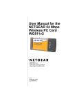
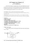
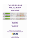
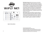
Please Read
Due to complex host set-ups or local/environmental influences, any
wireless network can suffer drop-outs, interference or connectivity
issues that would compromise the effectiveness of the system. XTA
have taken every possible step to ensure a fast, stable connection
within a capable system/environment, but instability caused by
external issues is beyond our control.
Page 2
Walkabout Kit User Manual & Operating Instructions
Introduction
XTA have spent a considerable period of time searching for a reliable, straightforward solution to creating a wireless
system that can interface with our units. The obvious choice of standard network is to utilise the ‘Ethernet’ system as
utilised by computer and control systems worldwide.
We have developed a new version of AudioCore to work with local area networks (LANs) and wireless local area
networks (WLANs) using the TCP/IP protocol. This system means there is no need for COM port redirection software or
to use external USB to serial converters. These can prove troublesome, especially with laptops.
We have found that the Netgear WG511T Wi-Fi card provides greatly extended range and improved stability, over and
above any WLAN systems built into laptops or tablet PCs (such as those featuring ‘Centrino’ processors).
The solution for the connection to the serial port on our processors is catered for by the DiGi WiSP WLAN to Serial
converter. This device is small, stable, and easy to set up. The setup of the WiSP is though a web interface so requires no
special software, although a small utility program is supplied to check that the device is available and reconfigure it if
necessary.
Contents of the kit
1: DIGI WiSP Wi-Fi to Serial Converter;
2: Power supply for WiSP;
3: Netgear Wi-Fi card;
4: Adapter cable for direct RS485
connection.
Also included, but not shown:
XTA Walkabout PC Set-up CD;
Netgear driver CD;
DIGI support CD
Important Note
Before you begin installing the Netgear wireless card or the WiSP interface, please make sure you have the latest version
of software in your unit(s).
Unit Type/Program Name
4 Series
DP226
DP224
DP6i
AudioCore
Earliest Compatible Version
V1.50
V3.60
V2.60
V2.3
V8.00
This software and the loader program are available from our website at www.xta.co.uk and is also included on the XTA
WiSP set-up disk supplied with this kit.
Note: This system, operating on TCP/IP, is only designed to control the 4 Series, DP226, DP224, and DP6i.
Inclusion of older units (DP100/200/202) will impair performance and is not recommended.
Page 3
Upgrading unit software
Note that this procedure can only be done one unit at a time – it is recommended that the unit being updated is
disconnected from any RS485 network until the procedure is complete.
Connect the unit to upgrade to a spare COM (serial) port on your PC or laptop. The serial cable must be a “one-to-one”
cable and NOT a null modem cable. This is because a null modem cable has “transmit” and “receive” wires swapped, and
so will not work. It is also possible to upgrade through an appropriate USB to RS232 converter, if your computer does not
have serial ports. The software cannot be updated via RS485.
Make sure the unit’s interface is set up as Master1 on RS232 and ID1, and that the baud rate is the same as that chosen in
the loader program (default is 38400). In the case of a DP6i, set the interface to 00. Plug the other end of the serial lead
into the RS232 port on the unit.
Run the loader program from the ‘Software’ folder on the CD called “Load226.exe”.
Select the correct COM port and baud rate, and press the
‘CONNECT’ button. If all is well, the loader will display
details of the connected unit.
At this point, press the “…” button beside the “File” text
box, and choose the correct bin file (selection will have
been automatically limited to software for the unit type
detected).
Do not switch off the unit during this procedure or attempt to run other software on the
computer. If the upgrade is interrupted, the unit will become inoperable and may have to
be returned to the factory.
Finally press the ‘Load Now’ button (which previously said ‘CONNECT’), and the unit will display
REMOTE LOAD
Block nnnn of 2048
The number nnnn will count up in sync with the number on the loader software and, when complete, the unit will reboot
and display the new version number and the message
New Software Loaded
In the case of the DP6i, the unit will reboot and flash nS (“new software”) to show that the update has been successful.
The entire process will take less than two minutes.
1
“Master” setting only on DP224/6/6i
4
Walkabout Kit User Manual & Operating Instructions
Installation
Set up the Netgear card first: Install the Netgear driver for the WG511T using the supplied Netgear driver disk
BEFORE plugging the card into your PC or laptop. Follow the instructions on screen. Now plug the card in – Windows
should recognise it and load the drivers as required. If, after installation, Windows then asks to load drivers itself, or
reports new hardware found, it is now safe to follow these instructions. If a warning is displayed select ‘Continue
Anyway’.
Set up the WiSP converter: There are no drivers required for the WiSP. All that needs to be done is to plug it into your
4 Series, DP226, DP224, or DP6i, using either an RS485 connection or RS232 connection, and plug in the power supply.
The settings for the WiSP have been pre-programmed by XTA at the factory and should not need changing.
The WiSP can directly output serial data in either RS232 or RS485 modes.
In RS232 mode, the module must be connected directly to the FIRST unit in the chain, in the
same way as if it was a direct wired connection from a PC or laptop. A standard RS232 lead,
wired 1-1 (NOT A NULL MODEM CABLE!) is used to plug the WiSP into the unit. The
RS232 cable should be no longer than 25 feet, or about 7 metres. The switch settings on
the back of the WiSP need to be set as shown below:
RS232 Mode
Switch 1 ON (UP)
Switch 2 – 4 OFF (DOWN)
For RS485 operation, use the adapter cable supplied in the kit and connect a standard mic cable
to this from the first unit in the chain. The total cable length for the RS485 system may be up
to 1000 metres (which includes cables between units). The switch settings on the back of the
WiSP need to be set as shown below:
RS485 Mode
Switch 1 OFF (DOWN)
Switch 2 OFF (DOWN)
Switch 3 ON(UP)
Switch 4 OFF (DOWN)
Page 5
BY DEFAULT THE WiSP IS SET TO WORK IN RS485 MODE.
Set up the Master unit: The Master unit is the first one in the chain, and has the WiSP directly connected to it
This may be either an RS232 connection or an RS485 connection, as explained in the past section.
RS485 connection (recommended)
For 2 Series units, the first one should be Master, RS485, 38400 baud and ID1, and following units
Slave, RS485, 38400 baud, ID2 (increment ID for each connected unit).
For RS485 connections the DP6i units should be set to interface 06 with incremental IDs.
Warning: The 4 Series by default are set to 115200 baud and this must be changed to 38400 for the system to work. On
an exclusive 4-Series network the baud rate can be increased to 115200, but the WiSP will need to be reconfigured.
Please see Appendix 1 for details of how to do this.
6
Walkabout Kit User Manual & Operating Instructions
RS232 connection
Alternatively, the WiSP may be set to RS232 mode
(by changing the DIP switches on it as explained on page 5) and connecting it as below.
Other units on the network should be set up as
Slave, RS485, 38400 baud, ID2 (increment ID for each connected unit).
[4 Series Interface Menu]
Or…
Slave, RS485, 38400 baud, ID2 (increment ID for each connected unit).
[DP224/6 Interface Menu]
In the case of a DP6i, set the interface to 09, which is the same as Master on RS232 at 38400 baud. For RS485
connections the DP6i units should be set to interface 06 with incremental IDs.
Warning: The 4 Series by default are set to 115200 baud and this must be changed to 38400 for the system to work. On
an exclusive 4-Series network the baud rate can be increased to 115200, but the WiSP will need to be reconfigured.
Please see Appendix 1 for details of how to do this.
Page 7
Set the Netgear Card IP Address
Whilst Windows will automatically assign the Wi-Fi card an IP address, our experience has shown that this must be
changed manually to ensure correct operation. Here’s what to do…
From your Windows desktop, click start, then ‘Control Panel’ to display…
The ‘Network
Connections’ icon is
already highlighted here.
Double click on the
‘Network Connections’
icon to display the list of
network connections in
place on the computer.
In this list should be the network associated with the Netgear wireless card – it is highlighted here.
Make sure you change the settings on the Netgear Card – check the “Device Name” column for “Netgear 108 Mbps
Wireless PC Card” as shown above. Right click on this and select ‘Properties’ to see how the card is set up – as shown on
the next page…
8
Walkabout Kit User Manual & Operating Instructions
The item listed (and highlighted) here that needs to be checked is the
‘Internet Protocol’ item – select it and then click on the ‘Properties’
button to reveal the window shown below, which gives access to the
actual IP address etc. used by the Wi-Fi card.
Make sure that ‘Use the following IP address’ is selected
and the IP address is similar to that shown (i.e. starting with
192.168.). If it is an auto-allocated address (typically of the
format 169.202.x.x), change it to one beginning 192.168,
but NOT ending with 224.226 as that’s the ADDRESS of the
WiSP!
Set the ‘Subnet Mask’ to 255.255.0.0.
Do NOT change the Default Gateway
setting (normally blank)!
Page 9
Search for and Establish a Wireless Link to the WiSP
On your Windows desktop, double click on the Netgear Wi-Fi icon in the system tray beside the clock. This will display a
window as below. Click onto the second tab on this window, ‘Networks’, to display…
Press the ‘Scan’ button and the card will try to find any available Wi-Fi networks in range.
If all is working, the name of the
network with the WiSP
connected should appear –
default is “XTA WISP”.
(All in capital letters!)
Assuming the network has now
been found, click on it in the list
(for example the one highlighted
in grey in the above screen shot)
and then the ‘Connect’ button.
The first tab will be selected again
automatically, with the blue bar at
the bottom showing the signal
strength, connection speed and
network name.
Make sure the following
parameters are set up:
Network Type is set to
‘Adhoc’;
Security settings are set with
‘WEP Encryption’ ticked, and
the ‘KEY1’ (entered manually
as to the left) is the matching
key on the WiSP – default is
1234567890, with ’64 bit’
encryption selected.
If this has been established, but AudioCore still says it cannot connect to the port, check the WEP encryption and the
KEY1 value entered – if these settings are incorrect, the connection can still be established (so the network name may
appear), but no data can be exchanged (hence AudioCore cannot use the network).
NOTE: A common error when setting up the Netgear card settings is to accidentally select the “Create with Passphrase”
button and enter the Key in the box associated with this, INSTEAD of the “Enter Key Manually” choice just below this.
Make sure you’ve not done this, as AudioCore won’t be able to find or control the units, even though the Netgear Card
will find the WiSP.
If you change any networking settings, always go back and check that this setting has not been overwritten or changed – in
certain circumstances if may be adjusted automatically causing the symptom described above..
Walkabout Kit User Manual & Operating Instructions
Setting up AudioCore to work with the WiSP
You will need to install AudioCore version 8.00 or greater on the PC to be used with the wireless system.
Start AudioCore as normal and then choose the menu Remote TCP/IP. The window below will be displayed.
Pressing the “Test Connection” button should display a message saying
“Connected to TCP/IP!” and the address/port number.
Assuming this works, you should now be able to go on-line, and use AudioCore as
normal. Nothing concerned with the operation of AudioCore has changed – you
will be able to upload and download as normal, and the real-time metering and
status monitor will be working as before.
If things don’t appear to be working, or an error message saying “Cannot connect
to port…” appears, please refer to the trouble shooting section on page 13.
It may take a up to a couple of minutes for the WLAN card to associate with the WiSP after booting up the PC/Laptop.
This is normal – the two LEDs on the Netgear card will flash independently until a connection is made, then they will begin
to flash together. Similarly, the green RX LED on the WiSP will flash at 1Hz until a wireless link is made; from which point
it will be a steady light, with a flash every 5 seconds.
The preprogrammed WiSP setting are given below – note the IP Address must match the IP Address in AudioCore.
Parameter
SSID
TCP/IP Address
Subnet Mask
WEP Encryption
WEP KEY1
Default Channel
Value
XTA WISP
192.168.224.226
255.255.0.0
Yes (64 Bit)
1234567890
6
Page 11
Useful Operation Hints
Tablet Features:
Some tablet PCs will have a feature whereby holding down the stylus acts like a right mouse click. You may want to turn
this feature off, as scrolling can be difficult. Please refer to your specific tablet PC operating manual for details.
Connection Problems:
Try experimenting with the location of the PC relative to the WiSP – sometimes the case of the computer can shield the
radio link. Also, try to ensure that the WiSP is not too close to the computer, or the radio link may saturate (overload).
6 feet (~2m) is a recommended minimum.
Check the Netgear and Windows Network icons in the system tray on the task bar – if there appears to be a problem,
double click on the Netgear icon to display the Netgear Wireless interface. Please refer to page 10 for detailed
instructions of how to check/re-establish a connection. Note that it can take anywhere between 1 to 3 minutes for a
network link to become available again. This is outside XTA’s control, so please be patient!
Moving radio links are more likely to lose connections than stationary ones, so if the link appears to be dropping out, try to
minimise movement until the link is re-established.
Computer Problems:
Please ensure all power-saving features are disabled on your computer.
Access this via start Settings Control Panel Power Options.
Depending on the version of Windows you are using, select power as ‘Always
On’, ensuring that the system never goes into stand-by.
Note that stand-by operation can also be enabled through the ‘Alarms’ tab (on a
laptop/tablet, used for low battery situations). Set the ‘Actions’ to be either ‘Do
Nothing’ or ‘Shut Down’. There is a known problem with Windows concerning
computers coming out of stand-by and subsequent communication with
peripheral devices (i.e. the Netgear card).
The latest driver for the Netgear card is always available from
www.netgear.com
AudioCore:
AudioCore will warn you if the radio link is lost during editing – this is to prevent accidental continuation of editing. The
quickest way to go back on-line after this is to press the ‘Refresh’ button - this bypasses the need to scan for connected
units etc.
Any changes to network or wireless settings may require AudioCore or even Windows to be restarted.
Walkabout Kit User Manual & Operating Instructions
Troubleshooting
Please ensure that any changes to your computer’s network settings, the WiSP settings, or the connected
XTA processors’ interface setting take place with AudioCore OFF-LINE.
Firstly, check again to see if the Netgear card has been able to find anything – see page 10 for details.
If there are still connection problems, it might be worth checking to see what IP addresses are being used by any Ethernet
devices connected to the computer. This is done through a ‘DOS Prompt’ window: Click Start, then ‘Run’ and type
‘Command’ in the list box.
This will open a ‘DOS Prompt’ window.
Within this window, type in
ipconfig /all
(with a space after the
‘ipconfig’ command). This
will display information similar
to that shown below:
As can be seen in this
example, the Netgear card is
set up on IP Address
192.168.7.7 and the Subnet
Mask is set to 255.255.0.0
If this does not correspond to the settings input as described earlier in this
section, review the settings and make sure that the check box labelled ‘Use
Windows to configure my wireless network settings is UNCHECKED.
This is the second tab available after clicking on the ‘Properties’ button as
explained at the start of this section.
If this all seems OK, and the IP address is what it should be, it is worth
checking at a low level to see if the WiSP can be located.
Open a ‘DOS Prompt’ window as before
and type in
ping 192.168.224.226
(with a space after the ‘ping’ command)
and press Enter.
This will try to find the device in the network by sending a series of small bursts (or packets) of information addressed
directly to the device, and will display the reply (if any). A typical outcome is shown here.
Page 13
Walkabout Kit Frequently Asked Questions
My laptop has Wi-Fi built in – can I use this?
The XTA Walkabout pack has been specifically designed for use with the supplied Netgear Wireless card. It is possible to
configure an internal Wi-Fi system to communicate with the WiSP. XTA does not recommend this approach, and we
cannot guarantee correct operation. However, if you wish to use the internal Wi-Fi, the required settings are on page 9
of this manual.
What sort of range can I expect with the system?
The standard 802.11b WLAN specification states that the approximate range available is 100m, in open space conditions,
assuming good line of sight is available. This distance will be reduced by using the system indoors (through walls), and if
there are large objects in the path.
Some of my units have not been updated to the latest software version – how will this affect the operation?
XTA strongly recommend that you perform the update as soon as possible – the system may work, but the speed of
operation will be greatly reduced and, in some circumstances, the system may not work at all.
Can I control my XTA units with SIA’s SMAART software, via the WiSP?
No. We believe that SIA’s SMAART does not currently support communication to XTA units via TCP/IP protocol.
Control can only be achieved via a hard-wired link using COM1 or 2, or a suitable MIDI interface.
However, it is possible to run SMAART and Audiocore at the same time, and resize the windows to allow the analysis to
be viewed, while also adjusting parameters wirelessly through AudioCore.
How can I extend the range of my wireless connection?
A discussion about improving the available range of a wireless network is beyond the scope of this document. However,
information on this topic can be found on Netgear’s website at www.netgear.com in the ‘Support’ section.
Do you sell the WiSP unit separately?
XTA only sells the WiSP Wireless adapter as part of the Walkabout kit as this is the only way we can guarantee correct
configuration. We cannot support technical enquiries regarding wireless operation unless we have first hand knowledge of
the system.
What’s your favourite colour?
XTA recommend blue, but this is at the user’s discretion.
Walkabout Kit User Manual & Operating Instructions
Appendix 1 – Changing the WiSP serial baud rate for use with exclusive 4 Series systems
PLEASE DO NOT ADJUST ANY SETTINGS OF THE WiSP UNLESS EXPRESSLY
MENTIONED IN THIS SECTION. FAILURE TO ADHERE TO THIS ADVICE MAY WELL
RESULT IN LOSS OF CONNECITON AND THE RESETTING PROCEDURE FOR THE
WiSP IS A COMPLICATED PROCEDURE!
Adjusting the baud rate is a simple procedure, but please follow the steps carefully and in order.
First, run the Digi Discovery tool on the XTA
support CD. Assuming you have an
established connection to begin with, the
software should run and immediately find the
WiSP, as shown here…
The WiSP is actually configured though a
standard web browser, with all configuration
settings and the web pages themselves, being
sent back from the device. Clever eh?!
To open a connection to the WiSP, simply
double click on it in the list (it is the only item
shown above) or select it, and click on “Open
web interface” from the choices of Device
Tasks on the left hand side of the window.
This should open your web browser, and present a web page as shown below, asking for login details.
The login details are
Username: root
Password: dbps
Page 15
The home page should load and a list of configuration sections is shown in a menu down the left hand side of the window:
Click on the “Serial Ports” link under “Configuration” – this will display…
Walkabout Kit User Manual & Operating Instructions
Click on the Port 1 link to open the configuration settings for this port. This will display…
Do NOT change any settings on this page! Scroll down the page and, at the bottom of it, you will see a link to “Basic Serial
Settings”. Click on this to get to the baud rate adjustment, as overleaf.
Page 17
Change the baud rate in the drop down list to 115200 as shown and BE SURE TO PRESS APPLY!
Then logout and close your browser.
It is highly recommended that both the WiSP is restarted and your laptop. Disconnect the power from the WiSP for about
10 seconds then reconnect.
You should now be able to connect to an exclusive 4 series system at 115k baud.
Walkabout Kit User Manual & Operating Instructions