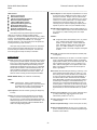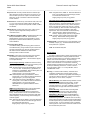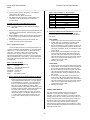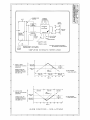
1
User's Manual: Series 260A Model 260A Process Current Loop-Powered Alarm INTRODUCTION: Table of Contents Page Introduction Description Specifications Installation Calibration General Maintenance These instructions cover the model types listed in Table 1 below. Supplementary sheets are attached for units with special options or features. 1 1 2 3 4 5 List of Drawings Table 1: A. Model Number Format: 260A-Input-Output-Mounting-Certification-Calibration B. Typical Model Number: 260A-20MA-SN-DIN-NCR Page Electrical Connections (4501-113) Calibration Connections & Simplified Schematic (4501114) Configuration DIP Switch Location (4501-115) Dimensions: DIN Rail Mounting (4501-116) Dimensions: Surface & Snaptrack Mounting (4501-117) NEMA 4 & 12 Enclosures (4501-118) Instrument Housing, With/Without Window (4501-121) Series 260A 6 7 8 9 10 11 12 -Output -SN -Mtg -DIN -SM -ST -N4 -N12 -IH -IHW -Cert. -NCR 2 Approval -Cal. (Blank) 1 -C Notes (Table 1): 1. Alarm can be ordered with or without the factory calibration "-C" option. Consult the selection & ordering guide for information required. Any customer specified calibration information will be included on a separate calibration label on the unit. 2. Consult the factory for current information on agency (e.g. Canadian Standards Association, etc.) approvals. IMPORTANT SAFETY CONSIDERATIONS It is very important for the user to consider the possible adverse effects of power, wiring, component, sensor, or software failures in designing any type of control or monitoring system. This is especially important where economic property loss or human life is involved. It is important that the user employ satisfactory overall system design. It is agreed between the Buyer and Acromag, that this is the Buyer's responsibility. Acromag, Inc. 30765 South Wixom Road PO Box 437 Wixom, Michigan 48393-7037, USA -Input -20MA DESCRIPTION: This two-wire, loop-powered alarm accepts a 4 to 20mA input signal and provides a failsafe, completely isolated, SPDT (1 Form C) dry contact relay output for switching AC or DC loads. The unit derives all operating power from the loop and has a voltage drop of only 4.5VDC. Being completely loop energized, this alarm is ideally suited to provide a local alarm indication for already existing 2, 3, or 4-wire transmitters, without the need for additional wiring. The alarm setpoint is fully adjustable from 4mA to 24mA. The setpoint voltage may be precisely read at the field wiring terminals of the unit. Internal DIP switches with Gold contacts allow the selection of HI/LO failsafe alarm action, six values of deadband, and latching or autoreset operation. An LED provides a visual indication of the alarm condition. Tel: (248) 624-1541 FAX: (248) 624-9234 The Alarm is RFI-protected, operates over a wide temperature range, and features excellent temperature coefficients which minimize the effects from harsh plant environments. See Drawing 4501-114 for a simplified schematic. Copyright 1991, 1994, Acromag, Inc., Printed in the USA. Data and specifications are subject to change without notice 8500-289-B94F009 -1- Series 260A User's Manual Process Current Loop-Powered Alarm ___________________________________________________________________________________________ 260A Features: • Signal (Loop) Powered • Alarm Status Indication • 4.5V DC Fixed Voltage Requirement • Multi-turn Setpoint Adjustment • 2 Amp (3A Max) SPDT Contacts • Adjustable Deadband (Hysteresis) • HI/LO Failsafe Alarm Action • Wide Ambient Temperature Range • Automatic or Manual Reset • Mounting Configuration Versatility Setpoint Adjust: The Alarm Setpoint is adjustable from 0 to 125% of input current span, readable as 0.2V DC (4mA) to 1.2V DC (24mA) at the terminals. Example: 0.6V DC at the terminals represents 50% of span, or 12mA. Resolution is 0.1% of span, continuous, on a 22-turn potentiometer. The setpoint voltage represents the true trip-point to within ±0.5% of span. By monitoring the input current and adjusting the setpoint pot, the setpoint may be set to within 0.1% (see Calibration section). Deadband Adjust (Hysteresis): Field selectable Deadband: 0.5, 1, 2, 4, 8, and 16 percent of span, set via an internal DIP switch (S1, positions 2-6). Refer to Drawing 4501-115 to adjust deadband. These field mounted loop-powered alarms are designed to utilize one of a number of customer-specified mounting configurations. The alarm is available for DIN-rail mounting, surface mounting, 3-inch SNAPTRACK plastic rail mounting, or in various housings. These housings include NEMA 4, 12, and rugged instrument enclosures. The model number of the unit specifies the mounting/enclosure type (refer to Table 1). OUTPUT: -SN: Single-Pole, Double Throw (SPDT), Form C, dry contact relay. Isolated contacts rated at 2A (3A Maximum), 28VDC, or 120V AC resistive. Contact material: fine Silver. Breakdown Voltage: 500V AC across contact gaps. Life, 1 Million operations at 1 amp, 28V DC. Operation: failsafe, coil normally energized, de-energizes on alarm. Alarm input wiring is inserted in the top of the unit, while output wiring is inserted in the bottom (field side) of the unit. Screws to secure the wiring are located on the front panel. Connectors are screw-clamp type and accept wire size up to #14 AWG. Alarm LED: The LED will be ON if the setpoint is exceeded (relay not energized). SPECIFICATIONS: Alarm Action: Failsafe High or Low Alarm. Can be field configured to trip on increasing signal (Failsafe HI Alarm), or decreasing signal (Failsafe LO Alarm), via an internal DIP switch (S2). Set S2 to C2 position for High Alarm, or the C1 position for Low Alarm. Refer to Drawing 4501-115 to adjust the alarm action. Relay is normally energized and becomes de-energized on alarm or signal failure. Function: This two-wire, loop-powered alarm accepts a 4 to 20mA input signal and provides a failsafe, completely isolated, SPDT (Form C) dry contact relay output for switching AC or DC loads. Unit includes full range setpoint adjustment utilizing a 22-turn potentiometer accessible from the front of the unit. Internal DIP switches allow the selection of HI/LO failsafe alarm action, six values of deadband, and latching or auto-reset operation. An LED provides a visual indication of the alarm condition. The alarm has various mounting and enclosure options available. Alarm Latch: Automatic Reset (Non-Latching), or Latching. Latch action enabled via internal DIP switch (S1, position 1). In the Non-Latching mode, the alarm will reset to its non-alarm state as soon as the signal is outside of the selected deadband. In the Latched mode, the alarm will reset when the local Reset button (labeled RST) is pushed, if the input signal is outside of the alarm region including the current deadband setting. For this reason, it is recommended that deadband be set to 0.5% for latching alarms. Latch action can be locked out by pushing down and turning the Reset (RST) button 1/4-turn to lock it in its depressed state, or via the on-board DIP switch (S1, position 1). MODEL/SERIES: 260A- (Color coded with a Yellow label) INPUT: -20MA: 4 to 20mA input. Power to operate this alarm is derived from the input signal loop. Input current should be limited to 50mA or less to prevent damage to the alarm. Alarm input is reverse polarity protected. Input Impedance: 225 ohms at 20mA, typical (input voltage drop: 4.5V DC). Reference Test Conditions: Input: 4 to 20mA; Setpoint at 20mA (1.0VDC); Failsafe High Alarm; Deadband 0.5% (all S1 switches OFF); Ambient 77oF (25oC). Isolation: The output contacts are isolated from the input/power circuits for common-mode voltages up to 250V AC, or 354V DC off ground, on a continuous basis (will withstand 1500V AC dielectric strength test for one minute without breakdown). This complies with test requirements outlined in ANSI/ISA S82.011988 for the voltage rating specified. Accuracy: Repeatable to within ±0.1% of input span for constant conditions (25oC). Ambient Temperature Range: -13oF to 167oF (-25oC to 75oC). Ambient Temperature Effect: Less than ±0.01% of output span per oF (± 0.018% per oC) over the ambient temperature range for reference test conditions. -2- Series 260A User's Manual Process Current Loop-Powered Alarm ___________________________________________________________________________________________ Response Time: The relay contacts switch from closed to open within 50mS for a step input change from 10% of span on one side of the alarm point, to 5% of span on the other side of the alarm point, for high or low alarms. Minimum time between events: 100mSec. -N12: Oil-Tight Enclosure, NEMA 12. Enclosure material and finish: 0.075 & 0.060 inch thick steel with gray hammertone enamel finish inside and out. Shipping weight: 6 pounds (2.7 Kg) packed. Instrument Housing, Water-Tight Enclosures: Option types listed below. Refer to Drawing 4501-121 for outline and clearance dimensions. Enclosure Materials: Body and cover Copper-free aluminum (less than 0.4%), Gasket - Neoprene. Finish: Corro-free epoxy powder coat, color gray. Hub size: 0.75 inch (Quantity 2). Alarm mounted in this housing is NOT explosion-proof but it does meet NEMA 4 (water-tight) requirements. Alarm is mounted within enclosure at factory. -IH: Instrument Housing, Water-Tight Enclosure (No Window). Shipping weight: 5 pounds (2.3 Kg) packed. -IHW: Instrument Housing, Water-Tight Enclosure (With Window). Window allows viewing of alarm LED. Shipping weight: 6 pounds (2.7 Kg) packed. RFI Resistance: Unit will not trip, under influence of RFI, when input is ± 0.5% of input span from setpoint voltage, with RFI field strengths of up to 10V/meter at frequencies of 27MHz, 151MHz, and 467 MHz. EMI Resistance: Unit will not trip when input is ±0.25% of input span from setpoint voltage with switching solenoids or commutator motors. Surge Withstand Capability (SWC): Input/Output terminations are rated per ANSI/IEEE C37.90-1978. Unit is tested to a standardized test waveform that is representative of surges (high frequency transient electrical interference), observed in actual installations. CERTIFICATION: Consult the factory for current information on the availability of agency (e.g. Canadian Standards Association, Factory Mutual, etc.) approvals. Construction (Basic Alarm): Circuit Board: Military grade FR-4 epoxy glass circuit board. Circuit Board Coating: Fungus resistant acrylic conformal coat. Terminals: Compression type, wire size 14 AWG maximum. DIP Switch Contacts: Gold flash over Nickel contacts. Mounting Position: Position insensitive. -NCR: No Certification Required. INSTALLATION: MOUNTING: A wide variety of mounting options and enclosures are available to meet the needs of the installation. The available models are listed below. The transmitter is shipped as a complete assembly. The alarm is packaged within a general purpose plastic housing and optionally mounted within a variety of protective enclosures. The alarm should be located in an area that is protected from dust, moisture, and corrosive atmospheres. The enclosure type determines the protection afforded in a particular environment and location, make sure that this is not compromised. Maximum operating ambient temperatures should be within -13 to 167oF (-25 to 75oC) for satisfactory performance. Connect as shown in Connection Drawing 4501-113. To verify calibration, refer to "CALIBRATION" section. General Purpose Housing: Available with various mounting options listed below. Case: Self-extinguishing NYLON Type 6.6 polyamide thermoplastic UL94 V-2, color black. -DIN: General Purpose Housing with DIN Rail-Mount. Mounts to "G" & "T" rails. "G" Rail (32mm), Type EN50035; "T" Rail (35mm), Type EN50022. Refer to Drawing 4501-116 for outline and clearance dimensions. Shipping Weight: 1 pound (0.45 Kg) packed. -SM: General Purpose Housing, Surface-Mount. Refer to Drawing 4501-117 for outline and clearance dimensions. Shipping Weight: 1 pound (0.45 Kg) packed. -ST: General Purpose Housing, SNAPTRACK™. Refer to Drawing 4501-117 for outline and clearance dimensions. Shipping Weight: 1 pound (0.45 Kg) packed. SNAPTRACK™ is a registered trademark of Reed Devices, Inc. Mounting: To mount the alarm assembly - Determine which configuration is utilized and consult the proper mounting instructions below. Refer to the appropriate outline drawing for mounting and clearance dimensions. Alarms can be mounted side-by-side on 1.0-inch centers, if required. DIN Rail Mounting: Use suitable fastening hardware to secure the DIN rail to the designated mounting surface. An alarm ordered with the DIN Rail mounting option (-DIN) can be mounted to either the "T" or "G" Rail. Installation of the alarm to the rail depends on the type of DIN rail used (see Drawing 4501-116). Surface Mounting: Secure the alarm to the designated mounting surface using two 6-32 screws. Note that the mounting bracket has screw slots to facilitate mounting. SNAPTRACK™ Mounting: Secure the SNAPTRACK™ mounting channel to the designated mounting surface using suitable fastening hardware. To install the unit in the mounting channel, place the bottom end of the mounting bracket between the rails and press the top (notched end) firmly until the bracket "snaps" into place. To remove the alarm, insert a screwdriver into the upper arm of the connector and twist to release the unit from the track and tip the unit out. NEMA 4 and 12 Enclosures: Option types are listed below. Refer to Drawing 4501-118 for outline and clearance dimensions. Alarm is mounted within the enclosure at the factory. These enclosures can also accommodate a second Series 260A Alarm with the surface-mount option (-SM option, ordered separately). Conduit mounting holes and fittings are customer supplied. -N4 : Water-Tight Enclosure, NEMA 4. Enclosure material and finish: 0.075 and 0.060 inch thick steel with gray hammertone enamel finish inside and out. Shipping weight: 6 pounds (2.7 Kg) packed. -3- Series 260A User's Manual Process Current Loop-Powered Alarm ___________________________________________________________________________________________ NEMA 4 & 12 Enclosure Mounting: Secure the enclosure assembly to the designated mounting surface using appropriate hardware. The alarm is secured within this enclosure using two screws. Note: It is recommended that the alarm be removed from the enclosure during the process of drilling holes, installing fittings and mounting the enclosure. Instrument Housing Mounting: Secure the enclosure assembly to the designated mounting position using appropriate hardware. Note: It is recommended that the alarm be removed from the enclosure during the process of mounting the enclosure. To remove the unit from the enclosure, remove two screws securing it to the bottom of the enclosure. After the enclosure is installed, reinstall the alarm into the enclosure. Position the unit at an angle that permits all wiring to be routed unobstructed through both ports. Secure the alarm assembly to the enclosure using two screws. Alarm - DIP Switch Configuration Procedure: The Loop-Alarm is quite universal in that it can be configured as a High (HI) or Low (LO) failsafe alarm, for six values of deadband (hysteresis), and for latching or auto-reset operation. Before the adjustment procedure can proceed, the DIP switches must be configured to the requirements of the application (refer to Drawing 4501-115 for details). To gain access to the DIP switches, first remove the alarm from the installation. Second, open the plastic case to get access to the DIP switches. Third, configure the DIP switches as described in the DIP switch Configuration procedure below. Fourth, install the circuit board into the plastic enclosure as described in the Assembly Procedure. Disassembly Procedure for the 260A Plastic Housing: The plastic housing has no screws, it "snaps" together. A flathead screwdriver (Acromag 5021-216 or equivalent) is needed to pry the housing apart as described in the following steps. Electrical Connections: The wire size used to connect the unit to the control system is not critical. All terminal strips can accommodate wire from 14-26 AWG. Strip back wire insulation 1/4-inch on each lead before installing into the terminal block. Input wiring may be shielded or unshielded twisted pair. Since common mode voltages can exist on signal wiring, adequate wire insulation should be used and proper wiring practices followed. It is recommended that input wiring be separated from alarm contact wiring for safety, as well as for low noise pickup. CAUTION: Do not push the screwdriver blade into the housing more than approximately 0.1 inches while prying it apart. Handling of the printed circuit board should only be done at a static-free workstation, otherwise damage to the electronics could result. 1. To begin disassembly (refer to Drawing 4501-115) place the screwdriver at point A (left side of the alarm). While pressing the blade into the seam, use a twisting motion to separate the sides slightly. Repeat this operation at point B. 2. Now that the two pieces have been partially separated, use the screwdriver blade to work the left side of the package loose by working around the alarm and carefully prying the sides further apart. Repeat this action until it is easy to remove the left side from the plastic pins holding the pieces together. 3. Repeat this operation for the right side starting at points C and D. 1. Input: Connect input per connection diagram, observe proper polarity. Note: Input/Output circuits are isolated from each other allowing the output circuit to operate with common mode voltages up to 250V AC, or 354V DC, off ground on a continuous basis. Power to operate the unit is derived from the input signal current--no external power supply is required. The alarm has an input voltage drop of 4.5V DC at 20mA. When a signal alarm is installed, it is always important to consider the voltage drop or additional line resistance that will be placed in the system. Any additional load tends to reduce the line or drive potential and may exceed the source rating. The effect of voltage drop within the system must be calculated to ensure that drive capability is not exceeded. 2. Output: Wire contacts as shown in Connection Drawing 4501-113 (see label on unit for relay type and contact rating). 3. Grounding: The alarm is packaged in a General Purpose plastic housing and does not require an earth ground connection. If the alarm is mounted in a metal housing, a ground wire connection is required. In this case, connect the ground terminal (Green Screw) to earth ground using suitable wire per applicable codes. DIP Switch Configuration: 1. High (HI) or Low (LO) Alarm action: DIP Switch S2. Set S2 to C1 for Low alarm, or set S2 to C2 for High alarm. Refer to Drawing 4501-115 for a graphical representation of each. Refer to table of Drawing 4501-115 for proper switch positions. 2. Deadband (Hysteresis): DIP Switch S1, positions 2-6. The deadband can be set to 0.5, 1, 2, 4, 8, or 16 percent of input span and must be configured when the alarm is going to be used in the Auto-Reset Mode (non-latching). Deadband is 0.5% with all switches OFF. DIP Switch S1, positions 2 through 6 individually select 1, 2, 4, 8, or 16 percent deadband. If the alarm is configured for the Latching Mode, configure the deadband for 0.5%. Refer to table of Drawing 4501-115 for proper switch positions. IMPORTANT: Noise and/or jitter on the input signal has the effect of reducing (narrowing) the instrument's deadband and may produce contact chatter. To reduce this undesired effect, increase the deadband setting. 3. Alarm Latch Enable: DIP Switch - S1, position 1. Set to OFF for Automatic Reset (Non-Latching), or ON for Latching. Refer to table of Drawing 4501-115 for proper switch positions. Note: The push button on the front of the module can also lockout the latch action by pushing down and turning this button to lock it in its depressed state. CALIBRATION: This section provides information for unit configuration and calibration. If the unit was factory calibrated, the DIP switches have already been placed in their proper positions and verification of the calibration can be made per the Adjustment Procedure. If the calibration of the unit is to be changed, first go to the "DIP Switch Configuration Procedure" below, before proceeding with the Alarm Adjustment Procedure. -4- Series 260A User's Manual Process Current Loop-Powered Alarm ___________________________________________________________________________________________ Table 2: Setpoint Voltage vs. Trip Point Input INPUT SETPOINT TERMINAL VOLTAGE (VDC) 4mA 0.200V 8mA 0.400V 12mA 0.600V 16mA 0.800V 20mA 1.000V 22mA 1.100V 24mA 1.200V 4. Important: Mark the Alarm's Configuration on the calibration label located on the enclosure. Example: IN: HI alarm, DB 8%, Non-latching. 5. After programming the DIP switches, install the Alarm circuit board back into its case as described in the assembly procedure below. Assembly Procedure for the 260A Plastic Housing: NOTE: The Model/Serial Number label is attached to the Right plastic side. 2. Setpoint calibration is complete. 1. Refer to Drawing 4501-115 and line up the right plastic side with the board and terminal assembly. Carefully but firmly press the pieces together. 2. Before installing the left side, place the mounting bracket (unique to the mounting type you have) around the pins at the back of the housing. 3. Line up the left side of the housing with the assembly and carefully, but firmly, press the pieces together. B. Input Current Method of Alarm Adjustment: For tight control applications where precise alarm trip points are required, proceed with the Input Current method of Setpoint Calibration given below: HIGH ALARMS 1. Adjust the input current to the precise alarm current desired. 2. For High Alarms, turn the setpoint pot clockwise until the relay changes states and the alarm LED turns OFF. 3. Now, turn the setpoint pot counter-clockwise very slowly, just until the relay changes states and the alarm LED turns ON. The setpoint is calibrated. Check your calibration as noted in step 4 below. 4. For High Alarms, check the setpoint by reducing the input current until the relay changes states and the alarm LED turns OFF. Then slowly increase the input current until the alarm just trips (LED turns ON). The input current should be within ±0.1% (±0.016mA) of the desired trip point. If not, perform steps 1 through 3 again. 5. Calibration is complete. Alarm - Adjustment Procedure: Connect the alarm as shown in Connection Drawing 4501-114. 1 There are two methods of setpoint adjustment; via setpoint voltage 2 (within 0.5%), or input current (within 0.1%). Both methods are given below. The setpoint voltage or input current should be measured to 0.1% accuracy or better for proper results. The setpoint adjust potentiometer is accessible on the front panel of the alarm (see Drawing 4501-114 for location). The screwdriver blade used to adjust the potentiometers should not be more than 0.1-inch (2.54mm) wide. Alarm - Calibration Example: MODEL : 260A-20MA-SN-DIN-NCR Input : 4 to 20mA Setpoint : 12mA (0.6V DC at terminals) Alarm Action : High (HI) Alarm Alarm Mode : Non-Latching Deadband : 8 percent Output : SPDT Relay Contacts LOW ALARMS 1. Adjust the input current to the precise alarm current desired. 2. For Low Alarms, turn the setpoint pot counter-clockwise until the relay changes states and the alarm LED turns OFF. 3. Now, turn the setpoint pot clockwise very slowly, just until the relay changes states and the alarm LED turns ON. The setpoint is calibrated. Check your calibration as noted in step 4 below. 4. For Low Alarms, check the setpoint by raising the input current until the relay changes states and the alarm LED turns OFF. Then slowly decrease the input current until the alarm just trips (LED turns ON). The input current should be within ±0.1% (±0.016mA) of the desired trip point. If not, perform steps 1 through 3 again. 5. Calibration is complete. A. Setpoint Voltage Adjustment Method (High & Low Alarms): 1. Measure the setpoint voltage at the terminals and adjust the setpoint potentiometer for 0.600V DC. The alarm setpoint is fully adjustable from 4 to 24mA. For most applications, there is no need to simulate the trip point value to the 4 to 20mA input in order to calibrate the setpoint. Simply measure the setpoint voltage between the (SP) and (-) input terminals and adjust the 22-turn setpoint potentiometer until the desired value is reached. Turn the setpoint pot clockwise to increase the setpoint, counter- clockwise to decrease the setpoint. This signal is adjustable from 0.2V to 1.2VDC, where 0.2VDC equals a 4mA trip point, and 1.2V DC equals a 24mA trip point (1.0V DC is equal to 20mA). GENERAL MAINTENANCE: This alarm contains solid-state components and requires no maintenance, except for periodic cleaning and calibration verification. When a failure is suspected, a convenient method for identifying a faulty alarm is to exchange it with a known good unit. It is highly recommended that a non-functioning alarm be returned to Acromag for repair, since Acromag used tested and burned-in parts, and in some cases, parts that have been selected for characteristics beyond that specified by the manufacturer. Further, Acromag has automated test equipment that thoroughly checks the performance of each alarm. -5-