1
User's Manual: Series 461A
Model 461A AC-Powered Alarm
INTRODUCTION:
Table of Contents
Page
Introduction..........................................................................
1
Description........................................................................... 1
Specifications....................................................................... 2
Installation............................................................................ 4
Calibration............................................................................ 5
General Maintenance...........................................................
6
These instructions cover the model types listed in Table 1
below. Supplementary sheets are attached for units with special
options or features.
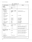
Table 1: A. Model Number Format:
461A-Input-Output-Power-Mounting-Cert-Calib
B. Typical Model Number: 461A-V5-SMRN-1-DIN-NCR
List of Drawings
Page
Electrical Connections (4501-542)....................................... 7
Calibration Connections (4501-543)....................................
8
Simplified Schematic & Contact Protection (4501-544).......
9
Configuration Jumper Location (4501-545).......................... 10
Failsafe/Non-Failsafe Alarm Conditions (4501-539)............
11
Dimensions: DIN Rail Mounting (4501-540)........................
12
Interposing Relay Connections (4501-541).......................... 13
Alarm / Two-Wire Transmitter Connections (4501-547)......
14
AC Sensor Connections (4501-546).................................... 15
Series
461A
Output
-SMRN
-DMRN
Pwr
-1
-2
Mtg
-DIN
Cert.
-NCR
Calib.
Blank
-C
Notes (Table 1):
1. The Alarm can be ordered with or without the factory calibration
("-C") option. Consult the selection and ordering guide for more
information. Any customer-specified calibration information will
be included on a separate calibration label on the unit.
2. Consult the factory for current information on agency (e.g.
Canadian Standards Association, etc.) approvals.
IMPORTANT SAFETY CONSIDERATIONS
DESCRIPTION:
It is very important for the user to consider the possible adverse
effects of power, wiring, component, sensor, or software failures in
designing any type of control or monitoring system. This is
especially important where economic property loss or human life is
involved. It is important that the user employ satisfactory overall
system design. It is agreed between the Buyer and Acromag, that
this is the Buyer's responsibility.
Acromag, Inc.
30765 South Wixom Road
P.O. Box 437
Wixom, Michigan 48393-7037, USA
Input
-V1
-V5
-V0
-V50
-V100
The Series 461A is an AC-powered, DIN-rail mounted alarm
family that accepts either a process current, or DC voltage input
signal, and provides single or dual alarm output relay contacts. The
Series 461A complements an entire family of Acromag flat-pack,
DIN-rail transmitters, alarms, and isolators, each designed to be
used as functional components that provide the user with a modular
solution for a wide range of field applications. The safe, compact,
rugged, and reliable design of this alarm allows it to be utilized in
either control room or field locations.
The electromechanical relay output provides one SPDT (Form
C) relay contact output (single alarm), or two SPDT (Form C) relay
contact outputs (dual alarm). The unit can be configured as a HIGH
or LOW single alarm, or a HIGH/HIGH, HIGH/LOW, LOW/HIGH or
LOW/LOW dual alarm. The operating mode of each relay can be
set to Failsafe (Normally Energized), or Non-Failsafe (Normally DeEnergized). The term 'Failsafe' refers to the condition that the relay
is energized during normal conditions, and de-energized upon alarm
or power loss to the unit. The Non-Failsafe mode of operation is
primarly used for simple control applications and acts opposite the
Failsafe mode--that is, the relay is energized during alarm
conditions.
Tel: (248) 624-1541
FAX: (248) 624-9234
Each channel has one pair of LED's (Green and Red) that
provide a visual indication of the alarm condition on the front of the
unit. When the Green LED is ON, it indicates a Normal condition,
and when the Red LED is ON, it indicates an Alarm condition. This
applies to both the Failsafe or Non-Failsafe operating mode. Thus,
line power status is simply indicated by an illuminated LED.
Copyright 1995 Acromag, Inc., Printed in the USA.
Data and specifications are subject to change without notice.
8500-546-A95H000
-1-
Series 461A User's Manual
Single/Dual Alarm
___________________________________________________________________________________________
SPECIFICATIONS:
The alarm setpoints are individually adjustable over the full input
range of the unit and the deadband for each setpoint is adjustable
from 1 to 100 percent. The setpoint voltage for each channel may
be monitored via DVM testpoints accessible from the front of the
unit. The deadband adjustment does not affect setpoint adjustment.
Rather, it determines the amount the input signal has to return into
the normal operating range before the relay contacts will transfer.
Deadband is normally used to eliminate false trips or alarm "chatter"
caused by fluctuations in the process input near the alarm point.
Function: This family of single or dual, DIN-rail mounted, ACpowered alarms, accept either a process current or voltage input
signal and provide a single or dual mechanical relay output.
Internal jumpers allow the alarm to be field-configured for use as
a HIGH or LOW alarm, in either Failsafe or Non-Failsafe
operating modes. The unit provides three-way isolation between
input, output, and power. Setpoint and Deadband adjustments
utilize 15-turn potentiometers. The Setpoint voltage can be
monitored via testpoints at the front panel (0-5V represents 0100% of input voltage span). The Deadband adjustment is a
'blind' adjustment between 1% and 100% of span. Red and
green status LED's provide a visual indication of the alarm
condition for each channel.
To implement an AC Current alarm for inputs up to 20A, an
optional AC current sensor (Acromag Model 5020-350, ordered
separately) is used in conjunction with the 0 to 1V DC (-V1) input
type configured for current input (external jumper required). The fullscale output of this transducer is 11.17mA DC. An internal 50Ω
shunt resistor installed in the module converts the 0-11.17mA
transducer signal to a 0-0.5585V DC input signal. The sensor itself
is an insulated, highly accurate toroidal instrument transformer, that
outputs a safe, low-level DC milliamp signal to the 461A’s analog
input terminals. The sensor is intended to be mounted close to the
current being measured and the wire connecting the sensor to the
461A’s input terminals can be up to 400 feet long (18 gauge wire).
The AC current input span is simply determined by the number of
primary turns passing through the center of the toroid. Example: a 0
to 20A AC input range requires one turn to pass through the hole in
the sensor, while a 0 to 5A AC input range requires four turns. See
specifications for other ranges.
MODEL/SERIES: 461A- (Color coded with a Yellow label)
INPUT: Unit can also be configured at the input terminal block for
either current or voltage input (-V1 and -V5 models only), see
connection diagram 4501-542. All input circuits utilize a high
impedance pull-down resistor (1MΩ for -V1 and -V5 units).
0 to 1V DC with 1MΩ minimum input impedance or 4 to
20mA DC into 50Ω shunt resistor (jumper required).
This range used with optional AC Current Sensor 5020350 (see drawings 4501-542 and 4501-546 for details).
0 to 5V DC with 1MΩ minimum input impedance or 4 to
-V5:
20mA DC into 250Ω shunt resistor (jumper required).
0 to 10V DC with 100KΩ minimum input impedance.
-V0:
-V50: 0 to 50V DC with 500KΩ minimum input impedance.
-V100: 0 to 100V DC with 1MΩ minimum input impedance.
-V1:
The 461A alarm is RFI-protected, operates over a wide
temperature range, and features excellent temperature coefficients
which minimize the effects from harsh plant environments. It is
available for 115V AC, or 230V AC power (for DC power, see the
Acromag Series 361A alarms). The versatile DIN rail mount can
accomodate a variety of mounting applications. See Drawing
4501-544 for a simplified schematic.
IMPORTANT: For the -V1 and -V5 input ranges, the 4-20mA
DC input range is selected via the installation of an external
jumper between the Input (L) and Input (+) terminals. This
connects an internal shunt resistor to the input.
Alarm input and power wiring is inserted at the top of the unit,
while output contact wiring is inserted at the bottom of the unit.
Screws to secure the wiring are located on the front panel.
Connectors are screw-clamp type and accept wire size from 26 to
14 AWG.
AC Current Sensor (5020-350): Optional - This sensor is a highly
accurate toroidal instrument transformer used to convert an AC
current signal to a low level DC milliampere signal of 0 to
11.17mA. The input AC current range is a simple function of
the number of turns placed on the AC Current Sensor (see
Table 2 below). The user configures the AC current sensor with
the required number of primary turns to obtain the desired input
span.
Key 461A Features:
Process Current or Voltage Input
•
Green/Red LED Trip/Power Indicators
•
Single or Dual Alarm
•
15-turn Setpoint Adjustment
•
HIGH/LOW Alarm Operation
•
15-turn Deadband Adjustment
•
Failsafe/Non-Failsafe Mode
•
Wide Ambient Temperature Range (-25°C to +75°C)
•
Mechanical Relay - 5A Contacts
•
AC Powered: 115V AC or 230V AC
•
Automatic Alarm Reset
•
No Point-to-Point Internal Wiring
•
Easy Field Jumper Configuration
•
Setpoint Voltage Monitor Points
•
Table 2: AC Sensor Turns
AC CURRENT
PRIMARY
INPUT RANGE
TURNS
0 to 20 Amps AC
1
0 to 10 Amps AC
2
0 to 5 Amps AC
4
0 to 2 Amps AC
10
0 to 1 Amps AC
20
SENSOR OUTPUT
(RED/BLACK WIRES)
0 to 11.17mA DC
0 to 11.17mA Dc
0 to 11.17mA DC
0 to 11.17mA DC
0 to 11.17mA DC
The output wires of the sensor are polarized: Red is (+) plus and
Black is (-) minus. Normally, these wires are attached to one
end of a cable (user supplied) and the other end connects to
one of the analog input's (+) and (-) terminals.
Input Burden: A function of the wire gauge resistance used for
the primary turns.
-2-
Series 461A User's Manual
Single/Dual Alarm
___________________________________________________________________________________________
Input Overload: The AC current sensor can withstand overloads
as follows:
•
•
•
-SMRN: Single Alarm (S), one Single-Pole, Double-Throw
(SPDT), Form C, electromagmetic (MR), dry-contact sealed
relay. Non-Latching (N)
-DMRN: Dual Alarm (D), two Single-Pole, Double Throw
(SPDT), Form C, electromagmetic (MR), dry-contact sealed
relay. Non-Latching (N).
20 times full-scale for 0.01 second
10 times full-scale for 0.1 second
5 times full-scale for 1.0 second
AC Current Sensor to Transmitter Wiring Distance: 400 feet
maximum for 18 AWG wire gauge. Other wire gauges can be
used as long as the resistance of both wires is less than 5.0Ω.
Alarm Mode: HIGH or LOW Alarm action is field-selectable via
internal jumpers (each channel on dual alarms). Can be
configured to trip on increasing signal (HIGH Alarm), or
decreasing signal (LOW Alarm). Refer to Jumper Configuration
Drawing 4501-545.
Setpoint Adjust: Adjustable from 0 to 115% of input voltage span.
The setpoint adjustments utilize 15-turn potentiometer(s)
accessible from the front of the instrument and provide linear
and continuous adjustment over the full input range of the unit.
Resolution is better than 0.1% of span, continuous. By
monitoring the input current and adjusting the setpoint pot, the
setpoint may be precisely set to within 0.1% (see Calibration
section). Optionally, the setpoint voltage may be monitored via
testpoints at the front of the module (0 to 5V represents 0 to
100% of input voltage span). These testpoints will accept up to
an 0.080 diameter probe tip (do not insert probe tip more than
0.4 inches deep). The setpoint voltage at these points
represents the true setpoint to within 1% of span. For current
inputs (Input [+] to Input [L] jumper installed), a setpoint voltage
of 1.0V represents 4mA and 5.0V represents 20mA.
Relay Operating Mode: Failsafe and Non-Failsafe operation is
field-selectable via internal jumpers (each channel of dual
alarms).
Failsafe (Normally Energized): The relay is energized (ON) in
the normal range of input, and de-energizes (drops out) when
the input signal value exceeds the setpoint, or power is lost.
Non-Failsafe (Normally De-energized): The relay is deenergized in the normal range of input and energizes (pulls-in)
when the input signal value exceeds the setpoint value.
Alarm LED's: A pair of LED's, one GREEN and one RED, indicate
the status of the alarm on a single alarm (two pairs of LED's on
dual alarms). The GREEN LED indicates a Normal condition
and the RED LED indicates an Alarm condition for both the
Failsafe and Non-Failsafe mode of operation. The logic of the
alarm is such that the Red LED is ON if the setpoint is
exceeded in either mode. Line power status is indicated by an
illuminated LED. If the LED(s) are off, check line power and the
power connections.
Deadband Adjust (Hysteresis): Deadband is adjustable from 1 to
100% of input span for each channel via 15-turn
potentiometer(s) accessible from the front of the unit. The alarm
deadband adjustments are independent on dual alarm models.
The deadband is adjusted with a screwdriver and provides
continuous blind adjustment over the full deadband range.
IMPORTANT: Noise and/or jitter on the input signal has the
effect of reducing (narrowing) the instrument's deadband and
may produce contact chatter. Another long term effect of
contact chatter is a reduction in the life of the mechanical relay
contacts. To reduce this undesired effect, you should increase
the deadband setting.
Isolation: Three way isolation; input, contacts, and power are
isolated from each other for common-mode voltages up to 250V
AC, or 354V DC off ground, on a continuous basis (will
withstand 1500V AC dielectric strength test for one minute
without breakdown). This complies with test requirements
outlined in ANSI/ISA S82.01-1988 for the voltage rating
specified.
Automatic Reset: The standard 461A alarm provides momentary
alarm action (Non-Latching). That is, the alarm will reset to its
non-alarm state as soon as the signal is outside of the selected
deadband.
POWER: -1: 115V AC ±10%, 50 to 60Hz, 0.032A.
-2: 230V AC ±10%, 50 to 60Hz, 0.016A.
Power Supply Effect: Trip-point varies less than ±0.05% of input
span for rated supply variations.
OUTPUT (Electromechanical Relays, fully sealed) - Contact
markings on the enclosure label are for a de-energized relay (off
the shelf condition). To control a higher amperage device, such
as a pump, an interposing relay may be used (see Drawing
4501-541).
Reference Test Conditions: Input: 1 to 5V; 250 ohm resistive
source; Setpoint at 5.0V DC; Failsafe High Alarm; Deadband
1%; Ambient 77oF (25oC), 115V AC supply.
Electrical Life - CSA Ratings:
25V DC, 5A, 100,000 operations, resistive.
48V DC, 0.8A, 100,000 operations, resistive.
240V DC, 0.1A, 100,000 operations, resistive.
120V AC, 5A, 30,000 operations, resistive.
240V AC, 5A, 30,000 operations, resistive.
Contact Material : Silver-cadmium oxide.
Breakdown Voltage: Between open contacts: 1000VAC rms,
between contacts and coil: 1500VAC rms, 50-60 Hz for one
minute.
Mechanical Life: 20 million operations. Note: External relay
contact protection is required for use with inductive loads.
Accuracy: Repeatable to better than ±0.1% of input span for
reference test conditions.
Ambient Temperature Range: -13oF to 167oF (-25oC to 75oC).
Ambient Temperature Effect: Less than ±0.01% of output span
per oF (± 0.018% per oC) over the ambient range for reference
test conditions.
-3-
Series 461A User's Manual
Single/Dual Alarm
___________________________________________________________________________________________
INSTALLATION:
Response Time: A built-in fixed time delay of 100 milliseconds
typical. That is, the relay will transfer ≤100 milliseconds after
the input signal exceeds the setpoint. This delay helps prevent
false alarming due to transient interference. The relay will
transfer within 50mS after the input passes the deadband
region, as it returns into the normal range. The Red LED will
light as soon as the input signal exceeds the setpoint, but the
relay will not transfer until after the time delay has expired.
When calibrating the alarm, the LED's should be observed to
indicate proper setpoint position.
The alarm is packaged in a general purpose type of enclosure.
Use an auxiliary enclosure to protect against unfavorable
environments and locations. Maximum operating ambient
temperatures should be within -13 to 167oF (-25 to 75oC) for
satisfactory performance. Connect as shown in the Connection
Diagram 4501-542. To verify calibration, refer to the
"CALIBRATION" section.
Mounting: Mount alarm assembly - refer to Drawing 4501-540 for
mounting and clearance dimensions.
Noise Rejection - Common Mode: Better than 100dB at 60 Hz,
250Ω unbalance, typical. Normal Mode: 26dB at 60 Hz, 250Ω
source, typical.
DIN Rail Mounting: Use suitable fastening hardware to secure
the DIN rail to the designated mounting surface. The alarm is
supplied with the DIN Rail mounting option (-DIN) and can be
mounted to either a "T" or "G" style rail. Installation of the alarm
to the rail depends on the type of DIN rail used. Units can be
mounted side by side on 1.6 inch centers, if required.
RFI Resistance: The unit will not trip under the influence of RFI
when the input is ±0.5% of input span from the setpoint voltage
for RFI field strengths up to 10V/meter, at frequencies of
27MHz, 151MHz, and 467MHz.
EMI Resistance: Unit will not trip when input is ±0.25% of input
span from the setpoint voltage with switching solenoids or
commutator motors.
"T" Rail (35mm), Type EN50022: To attach an alarm to this
style of DIN rail, angle the top of the unit towards the rail and
locate the top groove of the adapter over the upper lip of the rail.
Firmly push the unit towards the rail until it snaps solidly into
place. To remove an alarm, insert a screwdriver into the lower
arm of the connector and pull downwards while applying
outward pressure to the bottom of the unit.
Surge Withstand Capability (SWC): Input/Output terminations
are rated per ANSI/IEEE C37.90-1978. Unit is tested to a
standardized test waveform that is representative of surges
(high frequency transient electrical interference) observed in
actual installations.
"G" Rail (32mm), Type EN50035: To attach an alarm to this
style of DIN rail, angle the unit so that the upper groove of the
adapter hooks under the top lip of the rail. Firmly push the unit
towards the rail until it snaps solidly into place. To remove an
alarm, pull the lower part of the unit outwards until it releases
from the rail and lift the unit from rail.
Construction (Basic Alarm):
Printed Circuit Boards: Military grade FR-4 epoxy glass circuit
board, 0.063 inches thick.
Printed Circuit Board Coating: Fungus resistant acrylic
conformal coat.
Terminals: Compression type, wire size 14 AWG maximum.
Case: Self-extinguishing black NYLON Type 6.6 polyamide
thermoplastic, UL94 V-2. General Purpose, NEMA Type 1
enclosure.
Jumpers: Gold flash over nickel contacts.
Testpoints (Setpoint Voltage): Will accept up to an 0.080”
diameter probe tip. Do not insert probe tip more than 0.4” deep.
Mounting Position: Position insensitive.
Electrical Connections:
The wire size used to connect the unit to the control system is
not critical. All terminal strips can accommodate wire from 14-26
AWG. Strip back wire insulation 1/4-inch on each lead before
installing into the terminal block. Input wiring may be shielded or
unshielded twisted pair. Since common mode voltages can exist on
signal wiring, adequate wire insulation should be used and proper
wiring practices followed. It is recommended that input wiring be
separated from relay contact wiring for safety, as well as for low
noise pickup.
MOUNTING:
-DIN: General Purpose Housing, DIN-Rail Mount - accepts both
"G" Rail (32mm), Type EN50035, or "T" Rail (35mm), Type
EN50022. Refer to Drawing 4501-252 for outline and
clearance dimensions. Shipping Weight: 1 pound (0.45 Kg)
packed.
1. Power (Refer to Drawing 4501-542 for power connections):
The label on the unit specifies the AC power requirements.
Connect AC power as shown in Drawing 4501-542. Use
suitable wire per applicable codes. For 115VAC units, connect
the AC HOT power lead to the (L1) terminal and the AC
NEUTRAL power lead to the terminal marked (W). For 230VAC
units, connect the AC L1 power lead to the (L1) terminal and AC
L2 power lead to the terminal marked (L2). Connect the AC
GROUND lead to the (G) terminal (the AC Ground (G) terminal
is not connected internally).
CERTIFICATION: Consult the factory for current information on the
availability of agency (e.g. Canadian Standards Association,
Factory Mutual, etc.) approvals.
-NCR: No Certification Required.
2. Grounding: The alarm housing is plastic and does not require
an earth ground connection. If the alarm is mounted in a metal
housing, a ground wire connection is required. Connect the
ground terminal of the metal housing (Green Screw) to a
suitable earth ground using appropriate wire per applicable
codes.
-4-
Series 461A User's Manual
Single/Dual Alarm
___________________________________________________________________________________________
CALIBRATION:
3. Output Contacts: Wire contacts as shown in the connection
Drawing 4501-542. See label on unit for contact rating. Refer
to Drawing 4501-544 for suggestions on relay contact
protection.
This section provides information for unit configuration and
calibration. If the unit was factory calibrated, jumpers have been
placed in their proper positions and verification of the calibration can
be made per the Adjustment Procedure. If the calibration of the unit
is to be changed, first go to the "Shunt Block Configuration
Procedure", before going to the Alarm Adjustment Procedure."
Electromechanical Relay Contact Protection: To maximize
relay life with inductive loads, external protection is required. For
DC inductive loads, place a diode across the load (1N4006 or
equivalent) with cathode to (+) and anode to (-), see Drawing
4501-544. For AC inductive loads, place a MOV across the
load, see Drawing 4501-544.
Alarm - Shunt Block Configuration Procedure:
The Series 461A Alarm is quite universal in that it can be
configured as a HIGH (HI) or LOW (LO) alarm and can operate in
the Failsafe or Non-Failsafe mode. Before the adjustment procedure
can proceed, the jumpers must be configured for the requirements
of the application (refer to Drawing 4501-545 for details). To gain
access to the configuration jumpers, first remove the alarm from the
installation. Second, remove the circuit boards from the plastic
enclosure as described in the following Disassembly Procedure
(refer to Drawing 4501-545). Third, configure the jumpers (shunt
blocks) as described in the Jumper Configuration procedure below.
Fourth, install the circuit board into the plastic enclosure as
described in the Assembly Procedure.
IMPORTANT: Noise and/or jitter on the input signal has the
effect of reducing (narrowing) the instrument's deadband and
may produce contact chatter. The long term effect of this will
reduce the life of mechanical relays contacts. To reduce this
undesired effect, increase the deadband setting.
4. V/mA Input: Connect input per connection Drawing 4501-535.
Observe proper polarity. If the input is a 4 to 20mA signal, a
jumper must be installed between the Input (+) and Input (L)
terminals. Current is delivered to the Input (+) terminal and
returned at the Input (-) terminal. Voltage signals are connected
to the Input (+) and (-) terminals.
Disassembly Procedure for the 461A Plastic Housing:
NOTE: The Input, Output, and Power circuits are isolated from
each other, allowing the input circuit to operate with common
mode voltages up to 250V AC, or 354V DC, off ground, on a
continuous basis.
The plastic housing has no screws, it "snaps" together. A flathead screwdriver (Acromag 5021-216 or equivalent) is needed to pry
the housing apart as described in the following steps.
5. AC Current Input: The AC Current Sensor is isolated and can
be used in AC circuits up to 250V AC, 50 or 60 Hz. It is
designed to be mounted at the source of the AC current to be
measured. The sensor outputs a low-level DC milliampere
signal, allowing the transmitter to be mounted remote from the
AC signal using small gauge wire. The sensor's output
(Red/Black) wires can be shorted, open-circuited, or removed
from the transmitter’s input terminals, without hazard to
personnel or to the AC Current Sensor.
CAUTION: Do not push the screwdriver blade into the housing
more than approximately 0.1 inches while prying it apart. Handling
of the printed circuit board should only be done at a static-free
workstation, otherwise, damage to the electronics could result.
1. To begin disassembly (refer to Drawing 4501-545) place the
screwdriver at point A (left side of the alarm). While pressing
the blade into the seam, use a twisting motion to separate the
sides slightly. Repeat this operation at point B.
2. Now that the two pieces have been partially separated, use the
screwdriver blade to work the left side of the package loose by
working around the alarm and carefully prying the sides further
apart. Repeat this action until it is easy to remove the left side
from the plastic pins holding the pieces together.
3. Repeat this operation for the right side starting at points C & D.
AC Current Sensor: Per the Input Range chart in the
Specifications Section, loop the required number of turns
through the toroid for the full-scale range that you need in your
application. Use the cable tie provided to mechanically secure
the sensor. Refer to Drawing 4501-546.
DANGER: If the AC Current Sensor is used with an AC
Current Transformer (C.T.), disconnect power to the C.T., or
short the output of the C.T., before removing the wire going
through the AC Current Sensor. If this is not done, an open
circuited C.T. will generate high voltages (hazardous) and
possible C.T. damage.
CAUTION: If the two PC boards become separated while taking the
package apart, re-align the boards making sure that both
interconnection headers are aligned with their mating sockets and
carefully push the boards back together.
The sensor output wires should be connected to the extension
cable (wires) using wire nuts, or equivalent. Sensor output
wires are color coded RED (+) and BLACK (-), proper polarity
must be observed.
Shunt blocks are provided to accommodate in-field configuration
changes. In case of misplacement, additional shunt blocks may be
ordered from the factory. When ordering additional shunt blocks,
refer to Acromag Part Number 1004-332.
Jumper Configuration (Shunt Blocks):
1. HIGH (HI) or LOW (LO) Alarm action: Refer to table on
Drawing 4501-545 for proper jumper (shunt) position.
2. Failsafe or Non-Failsafe Mode: Refer to table on Drawing
4501-545 for proper jumper (shunt) position.
3. IMPORTANT: Mark the Alarm's Configuration on the calibration
label located on the enclosure. Example: CH1, HI, FS or CH2,
LO, NFS.
-5-
Series 461A User's Manual
Single/Dual Alarm
___________________________________________________________________________________________
4. After programming the jumpers, install the alarm circuit boards
back into their case as described in the assembly procedure
below.
4. Now, turn the setpoint potentiometer (SP1) counter-clockwise
very slowly, just until the relay changes states and the alarm
RED LED turns ON. The setpoint is now calibrated. Check
your calibration as noted in step 5 below.
5. For High Alarms, check the setpoint by reducing the input
current until the relay changes states and the alarm RED LED
turns OFF. Then slowly increase the input current until the
alarm just trips (RED LED turns ON). The input current should
be within ±0.1% (±0.016mA) of the desired trip point. If not,
perform steps 1 through 4 again.
6. If increased deadband is required, turn DB1 control clockwise.
Vary the input signal near the trip point and determine the input
values for pull-in and drop-out of the relay. The difference
between these values is the amount of deadband. Note that
readjusting the deadband potentiometer does not affect the
setpoint adjustment.
Assembly Procedure for the 461A Plastic Housing:
1. Refer to drawing 4501-545 and line up the left plastic side with
the board and terminal assembly. Carefully press the pieces
together.
2. Align the pins of the center section with the side and press the
pieces together.
3. Now line up the right side of the housing with the left side and
center assembly and carefully press the pieces together.
Alarm - Adjustment Procedure:
Connect the alarm as shown in Calibration Connection Drawing
4501-543. For best results, the input source must be adjustable
over the entire range of the unit and settable to an accuray of 0.1%
or better. The alarm status LED's can be used to indicate relay
action. The RED LED will turn ON when the relay changes state
from a non-alarm to an alarm condition, at the same time the
GREEN LED will turn OFF.
LOW ALARMS:
1. Set the deadband adjustment pot DB1 fully counter-clockwise for
minimum deadband (approximately 0.5% for a pure DC signal).
2. Adjust the input source for 12.000mA DC (value desired for
alarm setting in this example).
3. For LOW Alarms, turn the setpoint pot (SP1) counter-clockwise
until the relay changes state and the RED LED turns OFF.
4. Now, turn the setpoint potentiometer (SP1) clockwise very
slowly, just until the relay changes states and the RED LED
turns ON. The setpoint is now calibrated. Check your
calibration as noted in step 5 below.
5. For LOW Alarms, check the setpoint by raising the input current
until the relay changes states and the RED alarm LED turns
OFF. Then slowly decrease the input current until the alarm just
trips (RED LED turns ON). The input current should be within
±0.1% (±0.016mA) of the desired trip point. If not, perform
steps 1 through 4 again.
6. If increased deadband is required, turn DB1 control clockwise.
Vary the input signal near the trip point and determine the input
values for the pull-in and drop-out of the relay. The difference
between these values is the amount of deadband. Note that
readjusting the deadband potentiometer does not affect the
setpoint adjustment.
The setpoint and deadband potentiometers are accessible from
the front panel of the alarm (refer to Drawing 4501-543). The
screwdriver blade used to adjust the potentiometers should not be
more than 0.1 inch (2.54mm) wide.
Alarm - Calibration Example:
MODEL:
Input:
Setpoint:
Alarm Action:
Alarm Type:
Output:
461A-V1-SMRN-1-DIN-NCR (Single Alarm)
4 to 20mA - Install a jumper between the Input (+)
and Input (L) terminals for current input.
12mA
High (HI) Alarm
Failsafe
DPDT Relay Contacts
A. Adjustment Procedure (High and Low Alarms):
Notes (Adjustment Procedure):
1. The adjustment procedure is similar for other inputs.
2. The adjustment procedure is the the same for both Failsafe and
Non-Failsafe operation.
3. When the RED LED is ON, it indicates an alarm condition for
both the Failsafe and Non-Failsafe mode of operation. The
GREEN LED is ON when the signal is in the Normal operating
range.
4. If unit is a dual alarm (-DMRN models), repeat this procedure for
the second channel using the SP2 and DB2 adjustments
(SetPoint 2 and DeadBand 2).
5. Noise and/or jitter on the input signal has the effect of reducing
(narrowing) the instrument's deadband and may produce
contact chatter. To reduce this undesired effect, increase the
deadband setting.
NOTE: Optionally, the setpoint may be adjusted by connecting
a DVM to the setpoint voltage testpoints on the front of the
alarm. The voltage measured here is 0 to 5V, corresponding to
0 to 100% of input voltage span. For current inputs, a setpoint
voltage of 1 to 5V corresponds to 4 to 20mA of input current.
This setpoint voltage represents the true setpoint to within 1% of
input span and is a more convenient method of setpoint
adjustment where high precision is not required. These test
points will accept up to an 0.080 inch diameter probe tip (do not
insert probe tip more than 0.4 inches deep).
GENERAL MAINTENANCE:
This alarm contains solid-state components and requires no
maintenance except for periodic cleaning and calibration verification.
When a failure is suspected, a convenient method for identifying a
faulty alarm is to exchange it with a known good unit. It is highly
recommended that a non-functioning alarm be returned to Acromag
for repair, since Acromag uses tested and burned-in parts, and in
some cases, parts that have been selected for characteristics
beyond that specified by the manufacturer. Further, Acromag has
automated test equipment that thoroughly checks the performance
of each alarm.
HIGH ALARMS:
1. Set the deadband adjustment pot DB1 fully counter-clockwise for
minimum deadband (approximately 0.5% for a pure DC signal).
2. Adjust the input source for 12.000mA DC (value desired for
alarm setting in this example).
3. For High Alarms, turn the setpoint potentiometer (SP1)
clockwise, just until the relay changes states and the RED LED
turns OFF. If the RED LED is already off, proceed to step 4.
-6-