1
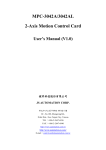
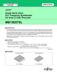
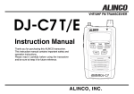
Edition 5.0
Jan. 2000
Fujitsu PLL Frequency Synthesizer
Evaluation Tool (Version 5.0)
User’s Manual
FUJITSU LIMITED
1
PLL Evaluation tool
(ver5.0)
CONTENTS
CHAPTER 1 : HARDWARE DESCRIPTION
1.1. INTRODUCTION
1.2. HARDWARE SETUP
1.3. INTERFACE BOARD DESCRIPTION
1.4. INTERFACE BOARD LAYOUT
CHAPTER 2 : SOFTWARE DESCRIPTION
2.1.Windows 95 VERSION
2.1.1.STANDARD SYSNTHESIZER(except for MB15E/FxxSL series)
2.1.1.1. INTRODUCTION
2.1.1.2. USED ENVERNOMENT
2.1.1.3. CONTENTS
2.1.1.4. SET UP
2.1.1.5. HOW TO USE THE PROGRAM
2.1.1.5.1. STARTING THE PROGRAM
2.1.1.5.2. SETTING THE TEST CONDITIONS
2.1.2.5.3. MEASUREMENT
2.1.2.5.4. OTHERS
2.1.2.STANDARD SYSNTHESIZER(MB15E/FxxSL series)
2.1.2.1. INTRODUCTION
2.1.2.2. USED ENVERNOMENT
2.1.2.3. CONTENTS
2.1.2.4. SET UP
2.1.2.5. HOW TO USE THE PROGRAM
CHAPTER 3 : EVALUATION BOARD DESCRIPTION
3.1. OVERVIEW
3.2. EVALUATION BOARD DESCRIPTION
3.2.1.MB1500EB01
3.2.2.MB1500EB01B
3.2.3.MB1500EB02
3.2.4.MB1500EB11
3.2.5.MB1500EB12
3.2.6.MB1500EB13
3.2.7.MB1500EB13B
3.2.8.MB1500EB14
3.2.9.MB1500EB16
3.2.10.MB1500EB16B
2
PLL Evaluation tool
(ver5.0)
CHAPTER 1. HARDWARE DESCRIPTION
1.1. INTRODUCTION
This evaluation tool is designed to demonstrate the operation of the FUJITSU MB15xx series PLL frequency
synthesizers. It will allow the user to investigate the operation capability of the IC and modify the loop parameters.
1.2. HARDWARE SETUP
This programming tool enables you to control FUJITSU PLL frequency synthesizers via a personal computer.
The personal computer is connected to the interface board via a parallel port. The programming software installed
generates signals to the interface board. Then, the signals are converted into control signals and sent to an IC on
the evaluation board.
Fig.1.1 Hardware constructure (image)
Parallel
Port
Key board
Interface
Board
PC
Evaluation
Board
Programm Device
file
1.3. INTERFACE BOARD DESCRIPTION
Fig. 1.2 The interface board top view
P/No. : MB1500EB00
Connector
Ground
Trigger switch
Delay control switch
Data output pins
BNC connector
Power source pins
3
PLL Evaluation tool
(ver5.0)
Connectors
The personal computer and the interface board is connected with a cable. The connector should have 25-pin[
connector for the personal computer’s printer port and 36-pin connector for the interface port.
Trigger Switch
Logical level of the trigger signal can be switched by the trigger switch.
/Q : Active high
Q : Active Low
Trigger
Trigger
BNC Connector
This connector should be connected to a time interval analyzer. A trigger signal is output through this connector.
Delay Control Switch
The delay time between the trigger signal and the last LE signal outputs can be adjusted by the delay control switch.
Turning the white screw part, the delay time can be adjusted in the range from 5µs to 600µs.
Data Output Pin
Connect one side of the three wire (white, blue and yellow) connector to the data output pins on the interface board.
The other side is connected to the data input pins on the evaluation board.
Power Source Pin
Connect two wire (red and black) connector to the power source pins, and the other side to ground and Vcc
respectively. (Vcc = 3V to 5V (needs to be as same as supply voltage for the IC))
Ground
Connect to ground.
4
PLL Evaluation tool
(ver5.0)
1.4.INTERFACE BOARD LAYOUT
5
PLL Evaluation tool
(ver5.0)
CHAPTER 2. SOFTWARE DESCRIPTION
2.1. Windows95 VERSION
2.1.1. STANDARD SYNTHESIZERS (except for MB15E/FxxSL series)
2.1.1.1. INTRODUCTION
This program is designed to demonstrate the operation of the Fujitsu PLL frequency synthesizers. It will allow the
user to investigate the operation capability of the IC and modify the loop parameters.
2.1.1.2. USED ENVERNOMENT
OS: Windows95
2.1.1.3. CONTENTS
FiPLL.exe
: Execution file to evaluate PLL series.
fjPLL.ini
: Initialization file
fjpll.vxd
: Virtual device driver
Applied device
MB15E03, MB15E03L, MB15E05, MB15E05L, MB15E06, MB15E07, MB15E07L, MB1516A, MB1517A, MB15A01,
MB15A02, MB15A16, MB15A17, MB15F02, MB15F02L, MB15F03, MB15F03L, MB15F04. MB15F05, MB15F05L,
MB15B03, MB15U10, MB1551, MB15C03, MB15C03, MB15U32
(The device file has to be housed in the directory "LIB" that locates under the same directory as FjPLL.exe does.
Do not change a name of the directory "LIB".)
Only the device file for MB15U10, name its suffix as DT2.
Name suffix for other device files as DT1.
2.1.1.4. SET UP
This programming tool consists of an interface board, a RF evaluation board and programming software.
1.Connect a parallel cable from the interface board to a printer port of a personal computer.
2.Connect the data input wire (three-wire; blue, yellow and white) from the interface board to
the Data, Clock and LE pins on the evaluation board. (Refer to CHAPTER 1.)
3.Insert the floppy disk into the floppy disk drive on the personal computer.
4.Change a disk drive from the current drive to the floppy disk drive.
6
PLL Evaluation tool
(ver5.0)
2.1.1.5. HOW TO USE THE PROGRAM
2.1.1.5.1. STARTING THE PROGRAM
Double clicking the FjPLL.exe on the windows explorer, and run the program. When you run the program using a
floppy disk, please release a protector of the floppy disk. If a write protect is valid, the following message is appeared
and the program does not run.
2.1.1.5.2. SETTING THE TEST CONDITIONS
The following window is opened on executing the FjPLL.exe.
1. Clicking exit program button, this program is quit.
2. Click the parallel port button and select a used port.
As is indicated below, you can select only valid parallel port.
7
PLL Evaluation tool
(ver5.0)
3. Select the device file and then click the button "OPEN".
The below shown parameter setting dialog window is opened. An usable parameter is different by the device file.
Set each parameter.
Only for a programmable parameter,
button becomes valid. Click each value.
of the parameter is not filled in, you can not go to the next step.
button and input data. If any
FjPLL dialog Parameter setting
OSC Frequency input
Frequency Range input
Channel Spacing input
Current Channel input
Hopping Channel input
Number of repeat input
: ALT + O
* Input a positive value
: ALT + F
* The value in the column "From" must be a positive number and
less than that in the column "To".
: ALT + S
* Input a positive value.
: ALT + C
* Input an integer(0 or more)
: ALT + H
* The value in the column "From CH#" must be an integer(0 more)
and less than the value in the column "To CH#".
: ALT + E
* Input an integer(1 or more)
Note : As regards "Frequency Range" value,
in the case that the display of data and real data differ, please confirm the value.
The value be inputed in conformity with the calculation "[(MxN)+A] x fr(channel spacing)".
8
PLL Evaluation tool
(ver5.0)
2.1.1.5.3. MEASUREMENT
After test conditions are entered, the measurement can be done by sending the serial data to the testing sample
via the interface board.
Hopping enable progress -- ALT + E
Hopping is repeated at designated time by "Number of repeat"
It can be cancelled using a space key.
Click the button "Output current Ch Data", then the value of the present channel is automatically calculated and
output through the port. Click the button "Output Next Ch Data", then the value of the next channel is automatically
calculated and output through the port.
In the both cases, serial data and an trigger is output.
If the calculation is failed, the PLL Frequency Hopping mode can not be selected. Set parameters correctly.
2.1.1.5.4. OHTERS
When any of OSC Frequency, Frequency Range and Channel Spacing is changed, the PLL Frequency Hopping
mode can not be selected. In that case, click the button "Output Current Ch Data".
There is not a function to save the set data.
Certainly house the device files in the LIB directory that locates in the same directory as FjPLL.exe.
Do not change the name of LIB directory.
Only the device file for MB15U10, name its suffix as DT2. Name suffix for other device files as DT1.
Apply DOS 8.3 type for the name of the device file.
9
PLL Evaluation tool
(ver5.0)
2.1.2. STANDARD SYNTHESIZERS (MB15E/FxxSL/F7xSP series)
2.1.2.1. INTRODUCTION
This program is designed to demonstrate the operation of PLL(MB15E/FxxSL series). It will allow the user to
investigate the operation capability of the IC and modify the loop parameters.
2.1.2.2. USED ENVERNOMENT
OS: Windows95
2.1.2.3. CONTENTS
FiPLL.exe
: Execution file to evaluate PLL series.
MB15ExxSL series -- version. 3.4.1
MB15FxxSL,F7xSP series -- version 3.3.2
fjPLL.ini
: Initialization file
fjpll.vxd
: Virtual device driver
Applied device
Version 3.4.1 -- MB15E03SL, MB15E05SL, MB15E07SL,
Version 3.3.2 -- MB15F02SL, MB15F03SL, MB15F07SL, MB15F08SL
(The device file has to be housed in the directory "LIB" that locates under the same directory as FjPLL.exe does.
Do not change a name of the directory "LIB".).
2.1.2.4. SET UP
This programming tool consists of an interface board, a RF evaluation board and programming software.
1.Connect a parallel cable from the interface board to a printer port of a personal computer.
2.Connect the data input wire (three-wire; blue, yellow and white) from the interface board to
the Data, Clock and LE pins on the evaluation board. (Refer to CHAPTER 1.)
3.Insert the floppy disk into the floppy disk drive on the personal computer.
4.Change a disk drive from the current drive to the floppy disk drive
2.1.2.4. HOW TO USE THE PROGRAM
It conforms to chapter 2.1.1.5.
The bit configuration differs from MB15E/Fxx and MB15E/FxxL series.
10
PLL Evaluation tool
(ver5.0)
3.EVALUATION BOARD DESCRIPTION
3.1. OVERVIEW
Some synthesizers are pin compatible or similar pin assignment, so that an evaluation board is used for several
PLLs. The below table shows PLL part number and corresponding evaluation board numbers.
Part No
Table.1 P/No. of synthesizers and corresponding Evaluation board.
PKG type
Eval. board No.
Part No.
PKG type
Eval. board No.
MB15Axx series
MB15Fxx series
MB15A01/
A02/A03
SSOP-16
MB1500EB01
MB1516A
SSOP-16
MB1500EB01
MB15A16
SSOP-16
MB1500EB01
MB1517A
SSOP-16
MB1500EB01
MB15A17
SSOP-16
MB1500EB01
MB15Bxx series
MB15B01
SSOP-20
MB1500EB11
MB15B03
SSOP-16
MB1500EB13
MB15B11/
B13
SSOP-20
MB1500EB11
MB15Exx series
MB15F02/
F02L/F02SL
SSOP-16
MB1500EB13
Bump Chip
Carrier-16
MB1500EB13B
SSOP-16
MB1500EB13
Bump Chip
Carrier-16
MB1500EB13B
MB15F06
SSOP-16
MB1500EB13
MB15F07SL
SSOP-16
MB1500EB13
Bump Chip
Carrier-16
MB1500EB13B
SSOP-16
MB1500EB13
Bump Chip
Carrier-16
MB1500EB13B
MB15F03/
F03L/F03SL
MB15F08SL
MB15Uxx series
SSOP-16
MB1500EB01
MB15U10
SSOP-20
MB1500EB12
Bump Chip
Carrier-16
MB1500EB01B
MB15U32
SSOP-20
MB1500EB14
SSOP-16
MB1500EB01
MB15Cxxx series
Bump Chip
Carrier-16
MB1500EB01B
MB15E06
SSOP-16
MB1500EB01
MB15E07/
E07L/E07SL
SSOP-16
MB1500EB01
Bump Chip
Carrier-16
MB1500EB01B
MB15E03/
E03L/E03SL
MB15E05/
E05L/E05SL
MB15C101
MB15C103
SSOP-8
MB1500EB02
Bump Chip
Carrier-16
MB1500EB02B
SSOP-8
MB1500EB02
Bump Chip
Carrier-16
MB1500EB02B
MB15F7xSP series
MB15F72SP
/F73SP/
F78SP
TSSOP-20
MB1500EB16
Bump Chip
Carrier-20
MB1500EB16B
There are some components attached on a board. They are used for every synthesizers in common, and not so much influence
to loop characteristics (except for low pass filter components.) Accordingly, additional components such as VCO, a reference
oscillator, optimized loop filter etc. should be properly arranged by customers according to application.
11
PLL Evaluation tool
(ver5.0)
3.2. EVALUATION BOARD DESCRIPTION
3.2.1 MB1500EB01
Fig.3.1 MB1500EB01 circuit image
C1
From an
oscillator
C’1
Vp
2
15
3
14
4
+
-
φP
Vcc
13
Vcc
C3
φR
fout or LD/fout
Vp
-
C’2
16
OSCout
C2
+
Vcc
1
OSCin
NC or ZC
5
12
Do
(FC or PS)
6
11
GND
LE
from a
LPF
7
10
C4 (LD or Xfin)
Data
8
R1
connector
9
fin
R2
SW
Clock
R3
VCO
VCO output
C5
+
-
VVCO
C’3
Table.2 Components list on the evaluation board
No.
Symbol
Value
No.
Symbol
12
Value
1
C1
1000pF
9
R1
18Ω
2
C2
0.1µF
10
R2
18Ω
3
C3
0.1µF
11
R3
18Ω
4
C4
1000pF
12
5
C5
0.1µF
13
6
C’1
10µF
14
7
C’2
10µF
15
8
C’3
10µF
16
PLL Evaluation tool
(ver5.0)
Fig.3.2 MB1500EB01 board layout
(Top view)
OSCIN
SW(PS)
Vcc
13pin
Vp
Connector
direction
VCO
Three pins
Vvco
(Bottom view)
SW(PS)
LE
Data
Clk
LPF
13
PLL Evaluation tool
(ver5.0)
3.2.2 MB1500EB01B
Fig.3.3 MB1500EB01B circuit image
C1
OSCin
From an
φR
oscillator
16
C’1
Vp
14
2
13
3
12
φP
Vp
+
C’2
1
OSCout
C2
+
Vcc
15
-
fout or LD/fout
Vcc
C3
Do
(FC or PS)
5
10
6
9
GND
LE
LPF
C4 (LD or Xfin)
R1
7
8
fin
from a
Data
Clock
R3
VCO
VCO output
+
C5
-
VVCO
C’3
Table.2 Components list on the evaluation board
No.
Symbol
Value
No.
Symbol
14
SW
11
4
R2
Vcc
NC or ZC
Value
1
C1
1000pF
9
R1
18Ω
2
C2
0.1µF
10
R2
18Ω
3
C3
0.1µF
11
R3
18Ω
4
C4
1000pF
12
5
C5
0.1µF
13
6
C’1
10µF
14
7
C’2
10µF
15
8
C’3
10µF
16
connector
PLL Evaluation tool
(ver5.0)
Fig.3.4 MB1500EB01B board layout
(Top view)
OSCIN
SW(PS)
Vcc
13pin
Vp
Connector
direction
VCO
Three pins
Vvco
(Bottom view)
SW(PS)
LE
Data
Clk
LPF
15
PLL Evaluation tool
(ver5.0)
3.2.3 MB1500EB02
Fig.3.5 MB1500EB02 circuit image
C3
Vcc
C’1
C1
1
+
Vcc
-
LPF
OSCin
2
7
Do
LD
3
R1
R2
fout
4
R3
C2
Vcc
6
GND
VCO
from a TCXO
8
SW
5
fin
Div
Table.3 Components list on the evaluation board
No.
Symbol
Value
No.
Symbol
16
Value
1
C1
0.1µF
5
R1
18Ω
2
C2
1000pF
6
R2
18Ω
3
C3
1000pF
7
R3
18Ω
4
C’1
10µF
PLL Evaluation tool
(ver5.0)
Fig.3.6 MB1500EB02 board layout
(Top view)
Vcc
LD
Div
VCO
Vvco
(Bottom view)
LPF
SW
17
PLL Evaluation tool
(ver5.0)
3.2.4 MB1500EB11
Fig.3.7 MB1500EB11 circuit image
1
C1
20
GND
From an
Clock
2
oscillator
19
OSCin
VCO output
C2
Data
3
18
4
17
OSCout
5
fp
7
14
VVCO
C5
13
(BSC1 or Vp1)
(BSC2 or Vp2)
9
12
Do1
LPF
Do2
10
BS1
11
BS2
Table.4 Components list on the evaluation board
No.
Symbol
Value
No.
Symbol
18
VCO
LD2
8
LPF
C6
15
LD1
C4
Vcc
Vcc2
6
VVCO
C7
16
fr
VCO
VCO output
fin2
Vcc1
C3
connector
LE
fin1
Vcc
from a
1
C1
1000pF
2
C2
1000pF
3
C3
0.1µF
4
C4
0.1µF
5
C5
0.1µF
6
C6
0.1µF
7
C7
1000pF
Value
PLL Evaluation tool
(ver5.0)
Fig.3.8 MB1500EB11 board layout
Connector
direction
(Top view)
Three pins
Vvco
VCO
Vcc1
Vcc2
Vvco
LD Do fr
1
LD Do fr
2
(Bottom view)
LE
Clk
LPF
LPF
fr Do LD
fr Do LD
19
PLL Evaluation tool
(ver5.0)
3.2.5 MB1500EB12
Fig.3.9 circuit image
SW4
SW2
R10
R9
R8
R7
R1
1
VDD
C1
VCO
R2
VVCO
ISET
2
PS
R4
VDD
14
VDD2
8
C6
13
LE
from a
12
9
P3/fr2
Data
connector
11
10
OSCout
Clock
Table.5 Components list on the evaluation board
No.
Symbol
Value
No.
Symbol
20
R5
fin2
OSCin
VDD
C8
C7
15
DGND
oscillator
VCO
VVCO
AGND
7
From an
LPF
16
6
C5
SW5
Do2
fin1
R3
C9
17
VDD1
5
C4
VCO output
Vp
Vp
4
C3
VDD
18
Do1
SW1
R6
P0/LD
3
VDD
SW3
19
P2/fp2
LPF
VDD
C2
20
P1/fp1
Value
1
C1
0.1µF
11
R2
2.2kΩ
2
C2
0.1µF
12
R3
51Ω
3
C3
0.1µF
13
R4
51Ω
4
C4
1000pF
14
R5
51Ω
5
C5
1000pF
15
R6
2.2kΩ
6
C6
0.1µF
16
R7
62kΩ
7
C7
1000pF
17
R8
15kΩ
8
C8
0.1µF
18
R9
12kΩ
9
C9
0.1µF
19
R10
5.1kΩ
10
R1
2.2kΩ
PLL Evaluation tool
(ver5.0)
Fig.3.10 MB1500EB12 board layout
(Top view)
SW3
SW2
VDD
LD
SW4
SW5
Vp
SW(PS)
Vvco
Do1
Do2
VCO
VCO
LPF
LPF
Vvco
Connector
direction
LE
VDD
Three pins
Clk
(Bottom view)
SW(PS)
Clk
LE
21
PLL Evaluation tool
(ver5.0)
3.2.6 MB1500EB13
Fig.3.11 MB1500EB13 circuit image
C1
From an
VCO output
R2
Vcc
VCO
+
3
14
4
13
LE
finRF
fin1
5
VccRF
6
C3
VVCO
11
LD/fout
-
SW
C4 C’2
XfinRF
7
22
R6
+
C6
-
8
VCO
C’4
VVCO
C5
+
-
C’3
9
LPF
DORF
Table.6 Components list on the evaluation board
Symbol
Value
No.
Symbol
Value
1
C1
1000pF
13
R1
51Ω
2
C2
1000pF
14
R2
51Ω
3
C3
0.1µF
15
R3
18Ω
4
C4
0.1µF
16
R4
18Ω
5
C5
1000pF
17
R5
18Ω
6
C6
0.1µF
18
R6
51Ω
7
C7
0.1µF
19
R7
18Ω
8
C8
1000pF
20
R8
18Ω
9
C’1
10µF
21
R9
18Ω
10
C’2
10µF
11
C’3
10µF
12
C’4
10µF
R9
R7
Vcc
PSRF
DoIF
No.
C8
SW
10
PSIF
LPF
R8
12
VccIF
-
VCO output
connector
Data
GNDIF
+
C’1
from a
15
OSCin
C2
R5
16
Clock
2
oscillator
R1
R3
R4
1
GNDRF
C7
PLL Evaluation tool
(ver5.0)
Fig.3.12 MB1500EB13 board layout
(Top view)
IF
Connector
direction
RF
CK
LE
Vvco
VCO
Three pins
VCO
Vvco
VCC
VCC
Do SW
(PS)
SW Do
(PS)
(Bottom view)
LE
Clk
LPF
LPF
SW(PS)
23
PLL Evaluation tool
(ver5.0)
3.2.7 MB1500EB13B
Fig.3.13 MB1500EB13B circuit image
GNDRF
C1
Clock
1
16
From an
VCO output
OSCin
oscillator
R1
R3
R4
C2
R2
R5
Vcc
VCO
C’1
+
fin1
+
Data
3
14
4
13
R8
12
6
VccRF
XfinRF
7
10
SW
R7
VCO
VCO
C’4
VVCO
C5
PSRF
DoIF
+
-
C’3
C7
DORF
LPF
Table.7Components list on the evaluation board
No.
Symbol
Value
No.
Symbol
24
-
R9
9
8
LPF
+
C6
11
LD/fout
PSIF
R6
finRF C8
Vcc
VccIF
C3
connector
LE
-
SW
C4 C’2
2
5
VVCO
-
GNDIF
from a
15
Value
1
C1
1000pF
13
R1
51Ω
2
C2
1000pF
14
R2
51Ω
3
C3
0.1µF
15
R3
18Ω
4
C4
0.1µF
16
R4
18Ω
5
C5
1000pF
17
R5
18Ω
6
C6
0.1µF
18
R6
51Ω
7
C7
0.1µF
19
R7
18Ω
8
C8
1000pF
20
R8
18Ω
9
C’1
10µF
21
R9
18Ω
10
C’2
10µF
11
C’3
10µF
12
C’4
10µF
PLL Evaluation tool
(ver5.0)
Fig.3.14 MB1500EB13B board layout
Connector
direction
(Top view)
Clk
LE
Three pins
Vvco
VCO
VCO
Vvco
Vcc
Vcc
Do Do
(Bottom view)
Clk
LPF
SW(PS)
LE
LPF
SW(PS)
25
PLL Evaluation tool
(ver5.0)
3.2.8 MB1500EB14
Fig.3.15 MB1500EB14 circuit image
2
19
DORF 3
18
4
17
5
16
C2
VpRF
GNDRF
VCO
R2
R4
20
VccRF
LPF
C3
1
C1
R1
C4
finRF
C5
XfinRF
R3
VVCO
GNDRF
From an
VCO output
oscillator
R5
C6 OSCin
GNDRF
C7
R6
LD/fout
15
6
7
14
8
13
9
12
10
11
C8
VpIF
C9
LPF
DOIF
C10
GNDIF
finIF
XfinIF
VVCO
C11
R7
VCO
C12
GNDRF
R8
R9
R10
LE
from a
Data
VCO output
connector
Clock
Table.8 Components list on the evaluation board
No.
Symbol
Value
No.
Symbol
26
Vcc
VccIF
Value
1
C1
0.1µF
13
R1
51Ω
2
C2
0.1µF
14
R2
18Ω
3
C3
0.1µF
15
R3
18Ω
4
C4
1.0nF
16
R4
18Ω
5
C5
1000pF
17
R5
51Ω
6
C6
1.0nF
18
R6
2KΩ
7
C7
0.1µF
19
R7
51Ω
8
C8
0.1µF
20
R8
18Ω
9
C9
0.1µF
21
R9
18Ω
10
C10
0.1µF
22
R10
18Ω
11
C11
1.0nF
12
C12
1000pF
PLL Evaluation tool
(ver5.0)
Fig.3.16 MB1500EB14 board layout
(Top view)
Vp Vcc
Vcc Vp
Vvco
Vvco
VCO
VCO
Clk
LE
(Bottom view)
LPF
LPF
27
PLL Evaluation tool
(ver5.0)
3.2.9 MB1500EB16
Fig.3.17 MB1500EB16 circuit image
From an oscillator
output
R6
R7
GND
R9
C1 finIF
R1
R8
C2
XfinIF
GNDIF
VVCO
VccIF
C3
VCO
SW
C10
PSIF
VpIF
C4
LPF
1
20
2
19
3
18
4
17
OSCIN
C9
DoIF
LD/fout
5
16
6
15
7
14
8
13
9
12
10
11
Clock
connector
LE
finRF
R2
C8
XfinRF
R12
R10 output
R11
C7
GNDRF
VCO
VccRF
PSRF
VpRF
C6
SW
C5
DoRF
Table.9 Components list on the evaluation board
No.
Symbol
Value
No.
Symbol
28
from a
Data
Value
1
C1
1000pF
13
R1
51Ω
2
C2
1000pF
14
R2
51Ω
3
C3
10µF
15
R3
18Ω
4
C4
10µF
16
R4
18Ω
5
C5
10µF
17
R5
18Ω
6
C6
10µF
18
R6
51Ω
7
C7
1000pF
19
R7
18Ω
8
C8
1000pF
20
R8
18Ω
9
C9
1000pF
21
R9
18Ω
10
C10
10µF
22
R10
18Ω
11
C11
10µF
23
R11
18Ω
24
R12
18Ω
C11
LPF
VVCO
PLL Evaluation tool
(ver5.0)
Fig.3.18 MB1500EB16board layout
LE
Data
CLK
(Top view)
OSCin
VCO
RF Block
LPF
VccIF
VpIF LD/fout VpRF VccRF
(Bottom view)
LPF
IF Block
VCO
29
PLL Evaluation tool
(ver5.0)
3.2.10 MB1500EB16B
Fig.3.19 MB1500EB16B circuit image
From
an oscillator
from a
connector
output
R6
C9
R7
R9
20
1
R1
OSCIN Clock Data
GND
C1
19
18
17
C2
VVCO
XfinIF
GNDIF
VCO
C10
C3
VccIF
2
15
3
14
4
13
VpIF
6
7
DoIF
8
9
10
LD/fout
DoRF
VpRF
Table.10 Components list on the evaluation board
No.
Symbol
Value
No.
Symbol
30
XfinRF
R2 R12
R10
R11
C7
GNDRF
VCO
VccRF
PSIF
C4
finRF
output
C11
12
5
SW
LE
C8
R8
LPF
16
finIF
11
PSRF
C5
Value
1
C1
1000pF
13
R1
51Ω
2
C2
1000pF
14
R2
51Ω
3
C3
10µF
15
R3
18Ω
4
C4
10µF
16
R4
18Ω
5
C5
10µF
17
R5
18Ω
6
C6
10µF
18
R6
51Ω
7
C7
1000pF
19
R7
18Ω
8
C8
1000pF
20
R8
18Ω
9
C9
1000pF
21
R9
18Ω
10
C10
10µF
22
R10
18Ω
11
C11
10µF
23
R11
18Ω
24
R12
18Ω
C6
SW
VVCO
LPF
PLL Evaluation tool
(ver5.0)
Fig.3.20 MB1500EB16board layout
LE
Data
CLK
(Top view)
OSCin
RF Block
VCO
LPF
VccIF VpIF LD/fout VpRF VccRF
(Bottom view)
IF Block
VCO
LPF
31