Transcript
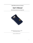
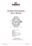
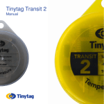
Technical Support (866) 908-TECH
EV-DW4955: Wireless Mini Door/Window Contact
USER MANUAL
Powering the EV-DW4955
For your added convenience, the EV-DW4955 comes with the battery
pre- installed. To activate, hold the EV-DW4955 firmly in one hand and
pull the plastic tab in the direction indicated.
Locate Transmitter
Select the location where the EV-DW4955 is to be mounted. NOTE: RF
signals can be affected by metal objects, including metal doors or large
mirrors. Such locations should be avoided as they can interfere with
proper operation.
Enrolling, Programming and Placement
Enroll the EV-DW4955 by programming the 6- digit serial number
(located on the EV-DW4955) into the receiver. Once the EV-DW4955 is
enrolled, you must perform a Module Placement test to ensure the
location you have chosen is suitable. Please refer to your receiver
Installation Manual for details.
Mounting the EV-DW4955 and Magnet
Once you have determined the proper location (see Enrolling,
Programming and Placement), the EV-DW4955 can be permanently
mounted.
NOTE: It is the responsibility of the installer to ensure that the
EV-DW4955 is securely mounted in the intended location.
PAGE 1
Using Provided Screws: Remove the back from the transmitter
(Figure A). Mount the back housing of the EV-DW4955, using the
screws supplied, to the desired location.
To remove cover, insert screwdriver
here and gently twist.
FIGURE A
Using Adhesive Tape: Ensure that the surface is clean and dry.
Apply the tape to the back of the EV-DW4955, press and hold firmly in
the desired location for approximately 10- 15s. It can take up to 24h
for the tape to reach maximum bonding strength.
Align the magnet with the notched arrow
on the EV-DW4955
housing (see Figure B). Mount the magnet a maximum of 5/ 8" (1.
8cm) from the EV-DW4955 by using the provided tape or screws. If
necessary use the spacers provided. Once the EV-DW4955 and magnet
are mounted, open and close the window/ door to ensure that none of
the parts interfere with this movement. Only one magnet can be used
for each EV-DW4955.
NOTE : The adhesive tape is not to be used in UL Installations.
FIGURE B
Magnet
5/ 8" space max.
(1.8cm)
Reed switch on
underside of PC
Board (in unit).
Symbol on side of
the case indicates
location of reed
switch
Out of the box the EV-DW4955 comes equipped with case tamper
detection. If the case is removed, the EV-DW4955 will report a zone
tamper to the control panel. For added security the EV-DW4955 was
designed to provide wall tamper monitoring as well. Simply replace the
short rubber actuator (see Figure C) with the longer one that is
included. With this option, if the case is opened or if the EV-DW4955 is
removed from it's location, a tamper will be sent to the control panel.
It is strongly recommended that mounting screws be used when using
the wall tamper option.
FIGURE C
Replacing the Battery
The EV-DW4955 requires one Renata CR2450N lithium battery. To
replace the battery, remove the cover as indicated in Figure A. Once
cover is removed, the battery will be visible. To remove battery, insert
a flathead screwdriver under the battery and gently twist (please refer
to Figure D for details). Wait 90 seconds then install the new battery,
placing positive side (+) up.
WARNING!: Battery may explode if mistreated. Do not
recharge, disassemble or dispose of in fire.
PAGE 2
This device complies with part 15 of the FCC Rules. Operation is subject to the following two conditions: (1) This device may not
cause harmful interference, and (2) this device must accept any interference received, including interference that may cause
undesired operation.
Any changes or modifications not expressly approved by the party responsible for compliance could void the user's authority to
operate the equipment
EV-DW4955 with back cover off
FIGURE D
Tamper Switch
PAGE 3
Tamper location
+
Battery (+ side up)
Insert screwdriver
here, gently twist
PC Board
Federal Communications
Commission (FCC) Statement
This equipment has been tested to FCC requirements and has been found acceptable for use.
The FCC requires the following statement for your information:
This equipment generates and uses radio frequency energy and if not installed and
used properly, that is, in strict accordance with the manufacturer's instructions, may cause
interference to radio and television reception. It has been type tested and found to comply
with the limits for a Class B computing device in accordance with the specifications in Part 15
of FCC Rules, which are designed to provide reasonable protection against such interference
in a residential installation. However, there is no guarantee that interference will not occur
in a particular installation. If this equipment does cause interferences to radio or television
reception, which can be determined by turning the equipment off and on, the user is
encouraged to try to correct the interference by one or more of the following measures:
• If using an indoor antenna, have a quality outdoor antenna installed.
• Reorient the receiving antenna until interference is reduced or eliminated
• Move the receiver away from the control/communicator.
• Move the antenna leads away from any wire runs to the control/communicator.
• Plug the control/communicator into a different outlet so that it and the receiver are on
different branch circuits.
If necessary, the user should consult the dealer or an experienced radio/television technician
for additional suggestions.
The user or installer may find the following booklets prepared by the Federal
Communications Commission helpful: “Interference Handbook”. This booklet is available from
the U.S. Government Printing Office, Washington, DC 20402. The user shall not make any
changes or modifications to the equipment unless authorized by the installation instructions
or User’s Manual. Unauthorized changes or modifications could void the user’s authority to
operate the equipment.
PAGE 4