1
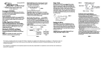
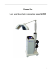
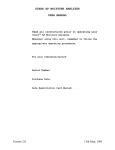
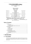
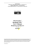
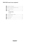
PIILIx-Design
USER MANUAL
EGTx Battery Operated
Exhaust Gas Thermometer
© 2015 PIILIx Design
Table Of Contents
1.
TECHNICAL DETAILS
3
1.1 General info�������������������������������������������������������������������������������� 3
1.2 Technical parameters����������������������������������������������������������������� 3
2.ASSEMBLY
4
2.1 Sensor assembly�������������������������������������������������������������������������� 4
2.2 Gauge assembly�������������������������������������������������������������������������� 4
3. USER MANUAL
5
3.1 ON-OFF operations������������������������������������������������������������������� 5
3.2 Reading and zeroing peak value����������������������������������������������� 5
3.3 Adjustment of the warning light���������������������������������������������� 5
3.4 Using of backlight����������������������������������������������������������������������� 5
3.5 Changing the battery����������������������������������������������������������������� 6
3.6Cleaning��������������������������������������������������������������������������������������� 7
3.7 Zero point calibration���������������������������������������������������������������� 7
3.8 WARNING AND WARRANTY���������������������������������������������� 7
Revision: A
Date: 13.09.2015
Written: Veli-Pekka Vuoristo
© PIILIx Design 2015
2
1. TECHNICAL DETAILS
1.1 General info
EGTx is a one channel battery powered microcontroller based exhaust gas
thermometer. It is designed for use with any K-type thermocouple sensor.
Picture-1 EGTx Exhaust Gas Thermometer
1.2 Technical parameters
SENSOR (not included in all sales packages):
Type of sensor: K-type
Type of tip:Insulated
Material of sensor body:
Inconel 600
Temperature range of sensor:
-50-+1100°C
Temperature range of sensor cable:
-50-+700°C
Temperature range of sensor connector:
-50-+220°C
GAUGE:
Measurement range: 0-999°C
Measurement resolution: ~4°C (8-bit)
Measurement accuracy (0-999°C): ± 7°C
Current consumption (no lights): 0.7mA
Type of battery: CR2450N 3V Lithium
Operation time without lights (25°C): approx. 800h
Operation time with backlight ON (25°C): approx. 200h
Operation time all lights ON (25°C): approx. 50h
Operational temperature range: -10C-+60°C
Protection class of the meter:
IP55 (splash proof)
Material of the case:
Anodized aluminium
Window material:
2mm acrylic plastic (hard coated)
Cold point compensation operational range:
-10-+60°C
Accuracy of the cold point compensation:
± 5°C
Dimensions, no cable (width x height x depth):
61 x 41 x 27 mm
© PIILIx Design 2015
3
2. ASSEMBLY
2.1 Sensor assembly
Sensor should preferably be assembled by TIG-welding (or by brazing in 2T
engines) the weld-nut to the exhaust pipe. You must drill 6mm (1/4”) hole for sensor
compression fixing kit to the exhaust pipe. Material of the weld-nut is stainless steel
(AISI 304).
The optimal place for the sensor in 2-stroke engine is something like 100-150mm
from the piston edge. A good practice is to locate the sensor after the point where fresh
inlet air oscillates during exhaust phase. This can be normally seen from the colour of
the exhaust pipe inner surface.
In 4-stroke engine suitable place for sensor is at the very beginning of the exhaust
pipe. In turbocharged engine sensor can be located before or after the turbine.
Sensor cable must be fixed with zip-ties etc in order to avoid vibration related
problems. Constant bending must be avoided.
To avoid electrical disturbances sensor cable must be located away from high
current and high voltage cables like ignition and alternator cables.
The woven protection layer of the sensor cable conducts electrical current. Please
be careful when routing cable near battery or any other live circuits. This same shield
may in some cases cause harmful ground loop currents. Sensor end of the shield is
grounded to the sensor body. If shield is touching vehicles body then this shield is
parallel connected to the engine grounding cable and it can conduct high currents
especially when starting the engine. Rubber grommets and shrink tubes are good for
insulation purposes.
2.2 Gauge assembly
Gauge can be fixed to the wanted position by 2-sided tape or by supplied special
fixing ‘3M Dual Lock™’ tape. To enable battery changing very rugged fixing is not
preferred.
If needed, small holes can be drilled to the back panel of the gauge. Please make
sure not to short-circuit battery and also take care to retain enclosure sealing against
water after modification.
In high vibration use like in RR motorcycles it is a good practice to use foamy
rubber or plastic for fixing. This will dampen the unwanted vibrations to acceptable
level.
© PIILIx Design 2015
4
3. USER MANUAL
3.1 ON-OFF operations
Gauge can be switched on by shortly pressing upper button. As an indication for
this a ‘888’ –will be shown shortly on display and immediately after that the gauge will
show the current temperature of the sensor.
Power can be switched OFF by pressing upper button for a couple of seconds, as
soon as power is off the display will also be off. Under the same upper button there is
additional operationality off backlight, more on chapter 3.4. Peak value and warning
light value are in memory and wont disappear during power-OFF. Chancing battery,
however resets these values and gauge needs reprogramming.
3.2 Reading and zeroing peak value
When ON the gauge will save the highest peak value in its memory. Peak temp can
be read from the memory by shortly pressing the lower button.
If lower button is pressed for longer time, first 2 seconds there will be peak value
on display. Then there is shown ‘0’ for indication of zeroing the peak value from the
memory.
Peak value will be kept in the memory even when the gauge is turned OFF. Battery
changing resets this value.
3.3 Adjustment of the warning light
Warning light adjustment can be done by the lower button. After a long pressing
of the lower button described in the chapter 3.2 there will be a further warning light
value showing and adjusting. If lower button is continuously pressed after peak value
operations the gauge will show it’s current warning light limit. If still pressed the
warning light value will scroll up with the steps of 5°C. If value is scrolled after 995°C,
it will roll over and continue again from 0°C. When suitable value is displayed button
pressing must be stopped and warning limit will be automatically saved to the value
last seen on the display. After this the gauge will return to a normal operation within
a couple of seconds.
NOTE! Lower button has been designed to register one long pressing only. If lifted
temporarily and then pressed again, the operation will not resume to the point where
last operation happened.
Warning light consumes a lot of current. To maximise battery life it is a good
practice to adjust warning light to flash only when really necessary.
3.4 Using of backlight
Backlight can be switched ON and OFF using upper button. When gauge is on,
you can turn backlight ON and OFF by shortly pressing upper button. State of the
backlight toggles with every short pressing of the button. After every pressing display
shows the status of the backlight; ‘888’ = Backlight ON, ‘000’ = Backlight OFF.
Default state of the backlight after turning the gauge on is OFF. After turning on
the gauge display shows ‘888’, in this operational phase this means ‘Gauge ON’ not
‘Backlight ON’.
Backlight consumes a lot of current. To maximise battery life use backlight
sparingly.
© PIILIx Design 2015
5
3.5 Changing the battery
‘Low battery’ warning is indicated by blinking the display. With this warning on
you can still use the gauge but after some time the reliability of the measurement
accuracy can be lost. Due to the battery chemistry this warning may sometimes come
prematurely when gauge is used in extreme cold temperatures. After heating the gauge
the operation will revert to a normal. Because of this known phenomena, it is advised
to use back- and warning light sparingly in cold climates.
Battery inside EGTx gauge is 3V lithium, type CR2450N. It is widely available
from battery shops. Please note the lithium batteries are listed dangerous in air
transportation. Because of these limits the manufacturer of this EGTx gauge (PIILIxDesign) cannot sell batteries other than the one supplied within the gauge.
Battery is located behind the back panel, inside the gauge. To change battery you
must remove back panel. To remove back panel unscrew all four Torx™ screws, size
of the correct tool is T10. Back panel seal may be stick to the gauge frame but the
panel can be easily removed by the help of chisel type screwdriver etc. Removing and
reassembling the battery is best to proceed as seen on Pictures 1-2. When reassembling
back panel, please make sure seal is correctly seated and do not overtighten the screws.
Frame is made of aluminium and threads can’t stand extreme torquing the screws.
Picture-2 Removing the battery
Picture-3 Battery reassembly
© PIILIx Design 2015
6
NOTE!
WHEN CHANGING BATTERY, PLEASE TAKE CARE NOT TO TOUCH ANY
INTERNAL CIRCUITS WITH THE BATTERY! RISK OF SHORT CIRCUITS AND
TOTAL FAILURE OF THE GAUGE!
Due to time in stock and the small data retention current consumption, the battery
supplied with the gauge may have shorter than normal operational life.
3.6 Cleaning
EGTx gauge frame and back panel is made of anodized aluminium and the front
window is acrylic/polycarbonate plastic. Use only mild washing liquids for cleaning.
Use of alkaline or heavy solvents may cause permanent damage to the surfaces of the
EGTx gauge.
Display window material is hard coated acrylic plastic with good resistance to
scratching. It however has no glass-like surface and will be harmed if wiped with
abrasive tools or cleaning fabrics.
3.7 Zero point calibration
EGTx gauge has zero point/offset calibration trimmer, located near the battery.
If for some reason the display value has drifted it can be readjusted back to accurate
reading using this internal trimmer. A good method for recalibration is to use correct
thermocouple calibrator but reasonable results can be achieved using for example
boiling water (100°C at sea level). Please do not touch this trimmer if you are not
familiar with thermocouple calibration.
3.8 WARNING AND WARRANTY
EGTx gauge has one (1) year warranty, including racing use. Warranty time
will be calculated from the day of purchase. Wire harness and sensor (if supplied)
has no warranty because manufacturer have no way to know the correct assembly
and operation of these. Failure in assembly and usage against sensible methods
may remarkably shorten the useful life of these components. Clear material and
manufacturing defects in the components are naturally included in the warranty.
Failure of the sensor or gauge may cause severe problems if the display value of the
EGTx gauge is the only method to analyse the behaviour of the engine. Manufacturer
strongly suggest to use all other methods (spark plug colour, AFR-value etc) to evaluate
the quality of ignition and fuel mapping before making any tuning based only on EGT
values. Because the manufacturer of the EGTx gauge has no real method to affect the
operations by the end user, all failures in engines etc are in no responsibility of the
EGTx gauge manufacturer.
EGTx gauge has no aviation authorities approvals. Use of EGTx in aeroplanes is in
sole responsibility of the end user.
© PIILIx Design 2015
7