1
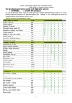
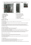
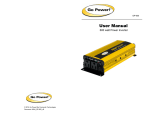
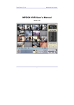
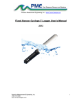
SIA
AG61/AG91
Extractors
Cod:0103079681
Important
The manufacturer cannot be held responsible for injuries or losses
caused by incorrect use or installation of this product. Please note
that the manufacturer reserve the right to invalidate the guarantee
supplied with this product following incorrect installation or misuse
of the appliance or use in a commercial environment.
This appliance is not designed to be used by people (including
children) with reduced physical, sensorial or mental capacity, or
who lack experience or knowledge about it, unless they have had
supervision or instructions on how to use the appliance by someone
who is responsible for their safety.
Under no circumstances should any external covers be removed for
servicing or maintenance except by suitably qualified personnel.
Appliance information:
Please enter the details on the appliance rating plate below for
reference, to assist Customer Care in the event of a fault with
your appliance and to register your appliance for guarantee purposes.
Appliance Model
Serial Number
CE Declarations of Conformity:
This appliance has been manufactured to the strictest standards and
complies with all applicable legislation, including Gas safety, Electrical
safety (LVD) and Electromagnetic Interference Compatibility (EMC).
2
IMPORTANT INFORMATION FOR CORRECT DISPOSAL OF THE
PRODUCT IN ACCORDANCE WITH EC DIRECTIVE 2002/96/EC.
At the end of its working life, the product must be taken to a special
local authority waste collection centre or to a dealer providing
appliance recycling services.
Disposing of a household appliance separately avoids possible
negative consequences for the environment and health. It also
enables the constituent materials to be recovered, saving both energy
and resources. As a reminder of the need to dispose of household
appliances separately, the product is marked with a crossed-out
wheeled dustbin .
Please note:
• Under no circumstances should the extractor be connected to any
gas ventilation system, flue system or hot air ducting system.
• Do not vent the extractor into an attic or loft space.
• Only install the extractor in rooms with adequate ventilation.
Remember that the extractor is powerful and whatever air is extracted needs to be replaced.
• Do not tile the extractor in. It should be removable for service or
maintenance.
• Do not use silicone sealant to secure the extractor to the wall.
• You must be able to isolate the extractor from the mains electrical
supply after installation.
• This extractor has been designed to be used in a room with a
volume of less than 36m3.
3
• Steam cleaners must not be used when cleaning this appliance.
• The performance of your extractor will vary depending on a number
of factors. These include: type of extraction, length of ducting, room
volume, ventilation available and cleanliness of the filters.
Note:
For best performance, you should switch on the extractor 15 minutes
before starting to cook and leave it to run for approximately 15
minutes after the end of cooking.
4
A
Press button “A”.
Press button “C ”.
B
C
Care and Maintenance
IMPORTANT : DO NOT PERFORM
MAINTENANCE OR CLEANING OF
THE EXTRACTOR WITHOUT FIRST
SWITCHING OFF THE ELECTRICITY
SUPPLY.
Cleaning
You should use a nonabrasive cleaner.
Any abrasive cleaner (including Cif) will
scratch the surface and could erase the
control panel markings.
by simply using a dilute solution of
water and mild detergent and drying to
a shine with a clean cloth.
Fig. 3
Fig. 4
The grease filter should be kept clean
to minimise the risk of fire.
At least once a month you should
Fig. 5
remove the grease filter and clean
it with hot soapy water. You can also wash the grease filter in a
dishwasher, ensuring that you place it in an upright position to prevent
damage from other items in the dishwasher.
7
To remove the grease filter
• Open the hinged panel as shown in Fig. 3.
• Push in the button on the handle and then pull down on the filter at
the top as shown in Fig. 4.
• When you have released it at the top, then you can pull the filter out
completely.
After rinsing and drying, reassemble the grease filter to the hood by
reversing the removal process.
Please note:
Cleaning the grease filter in the dishwasher may lead to
discolouration. This is normal and does not constitute a fault with the
appliance.
Changing the charcoal filter (re-circulating only)
To ensure best performance of your extractor, you should replace the
charcoal filter every four to six months, depending on use.
To attach a charcoal filter:
• Remove the grease filter as described above.
• Offer up the charcoal filter so that the magnetic pins are facing
upwards, one to the rear and one to eiach side. The filter will be
held in place by magnetic force.
• Finally, replace the grease filter.
IMPORTANT: Steam cleaners must not be used to clean this
appliance.
8
Changing the Light
DO NOT CHANGE THE LIGHT BULB IMMEDIATELY AFTER USE AS
THE BULB WILL BE HOT. ALLOW IT TO COOL BEFORE REMOVING IT.
Remove the grease filters.Unscrew the light bulb and replace with the
required light bulb as shown in the table below. Finally replace the
grease filters.
Do not touch bulbs or adjacent areas during or straight after prolonged
use of the lights.
The light is designed for use during cooking and not for general room
illumination. Extended use of the light can reduce the life span of the bulb.
Bulb replacement is not covered by the guarantee.
Only use bulbs recommended for your extractor. Do not fit bulbs of a
higher power rating.
Bulbs of a lower power rating may be adequate for use, generally last
longer and use less energy.
AG61/AG91
GU10 28W 240V
9
Mains Electricity Connection
THIS APPLIANCE MUST BE CONNECTED TO THE MAINS SUPPLY
BY A COMPETENT PERSON, USING FIXED WIRING VIA A DOUBLE
POLE SWITCHED FUSED SPUR OUTLET AND PROTECTED BY A
3A FUSE.
We recommend that the appliance is
connected by a qualified electrician,
who is a member of the N.I.C.E.I.C. and
who will comply with the I.E.T. and local
regulations.
The wires in the mains lead of this
appliance are coloured in accordance
with the following code:
Green & Yellow = Earth
Blue = Neutral
Brown = Live
DOUBLE POLE
SWITCHED
FUSED SPUR OUTLET
USE A 3 AMP FUSE
As the colours of the wires in the mains lead for the appliance may
not correspond with the coloured markings identifying the terminals
connecting to the fused spur, proceed as follows:
•The wire which is coloured green and yellow must be connected to
the terminal marked “E” (Earth) or coloured green.
•The wire which is coloured blue must be connected to the terminal
marked “N” (Neutral) or coloured black.
•The wire which is coloured brown must be connected to the
terminal marked “L” (Live), or coloured red.
Note: Use a 3A Fuse.
10
Assembly and electrical connection should be carried out by
specialised personnel.
When installing this product we recommend you seek the help of
another individual.
Electrical Information
Mains electrical voltage:
230 – 240Vac
Total rated power consumption:
176W
If your extractor is not working:
2. Check that the fuse in the spur has not blown.
11
Mounting Your
Extractor
Your extractor can be used to filter and
recycle the air within your kitchen, or to
extract the air outside.
D
B
When installing this appliance over a
hob, the clearance between the extractor
and the hob must be equal to or exceed
550mm. This instruction overrides the
instructions supplied with the hob.
(The height should be measured from
the top of the hotplates or burners).
A
C
Gas: 550mm minimum
Electric: 550mm minimum
Fig. 6
Where the extractor is to be installed
above a non hob, the instructions
supplied with the hob may dictate that
the height required above the hob is
greater than 550mm.
AG61
AG91
A
94
94
B
297
297
C
130
130
D
75
75
IN THE ABSENCE OF ANY INSTRUCTIONS SUPPLIED WITH A
GAS HOB, THE MINIMUM DISTANCE BETWEEN THE HOB AND
EXTRACTOR MUST BE AT LEAST 760mm.
The width of any hob must not be greater than the width of the
extractor installed above it.
12
Installation
The metal casing of this appliance has been coated with a
preservative to protect it during transport and storage. This
should be removed during installation by using a non-abrasive
stainless steel cleaner. Always follow the instructions given with
the cleaner being used.
When correctly installed, your product meets all safety
requirements laid down for this type of product. However, special
care should be taken around the rear of the appliance as these
areas are not designed or intended to be touched and may contain
sharp or rough edges that could cause injury.
Ducting and Ventilation
For best performance and lowest noise output, we recommend the
use of 125mm ducting. 100mm ducting may be used but this will
reduce performance and increase the noise of the extractor.
13
Mark wall
required
(see Fig.5)
Mark
out as
wall
as required,
see Fig 9.
Tools required.
Tools required
8
Fig. 8
Fig. 7
Fig. 8
Drill six mounting holes.
Fit wall fixings and top screws.
Fit wallthat
fixings
and
top screws
- Ensure
Ensure
any
fixings
you use
are
appropriate
for you
theuse
wallaretype.
that any fixings
appropriate
Drill 6 holes for mounting the body
for the wall type.
Fig. 9
Fig. 9
Fig. 10
Fig. 10
IMPORTANT SAFETY WARNING: ONLY USE THE SCREWS PROVIDED
WITH THE EXTRACTOR TO MOUNT THE DUCTING ADAPTOR. THE USE
OF LONGER SCREWS MAY CAUSE DAMAGE TO THE INTERNAL WIRING
WHICH WILL NOT BE COVERED BY THE WARRANTY.
14
FitFitthe
ducting
adaptor.
ducting
adaptor
Fig. 11
Fig. 11
Fix ducting and seal joints.
Fig. 12
Mount the chimney.
Adjust and secure the chimney.
Fig. 13
Fig. 14
E & O E. All instructions, dimensions and illustrations are provided for guidance only. SIA reserve the
right to change specifications without prior notice.
15
Please call for Service,
contact number: 01623 752919
[email protected]
12