1
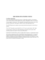
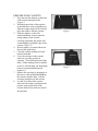
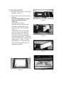
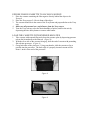
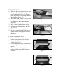
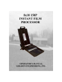
150P OPERATING INSTRUCTIONS
SYSTEM OVERVIEW
The 8”x10” Manual Film Processing system is a lightweight, portable, self-contained
system which produces finished, high quality, positive radiographs without conventional
wet processing or a dark room. The components which make up the system are the 150P
processor, film positive and negative, and the cassette with intensifying screen.
The 150P film processor contains no processing chemicals and requires no electricity to
operate.
The 8”x10” Polaroid® cassette Model 85-6 or 85-7 may be used with the 150P. Both
cassettes feature a built-in rare earth intensifying screen and a pressure plate which
maximizes film/screen contact evenly over the film surface.
Polaroid® TPX and 803 films consist of a light-sensitive negative in a light-tight envelope,
and a positive imaging sheet with an attached pod of processing chemicals. An exposed
negative (held in the cassette) and a positive sheet are fed through the processor rollers
together, breaking the pod and spreading processing chemicals over the image area. After
the recommended processing time, the film is peeled apart and the negative discarded. The
positive sheet is available for immediate viewing.
PREPARE FILM CASSETTE
1.
2.
3.
4.
5.
6.
7.
8.
Press the two blue buttons on the back
of the cassette and open it flat.
(Figure 1)
With the printed side of the negative
up and the three arrows pointing away
from the orange tongue of the cassette,
place the negative into the cassette.
Slide the negative so the fold
underneath hooks securely onto the
orange tongue of the cassette.
Correctly positioned, the packet will
extend slightly beyond the edge of the
cassette. (Figure 2)
Be sure negative is centered between
the two blue guide lines.
Close the cassette making sure both
buttons latch shut.
Leave the envelope in the cassette
until you are ready to make an
exposure. This will help prevent light
leaks. (When loading several cassettes
at once it will also help you distinguish
between exposed and unexposed
negatives.)
Remove the envelope by grasping it at
the arrows with one hand and holding
the cassette with the other. Pull the
envelope straight out of the cassette.
Lay the silver side of the cassette
down on a flat surface and depress the
pressure plate on the back of the
cassette until all four locks are locked
into position.
Figure 1
Figure 2
LOAD THE POSITIVE
1.
Open the 150P processor so both sides
laying flat. (Figure 3)
2.
Place the film positive in the processor
as follows:
- DO NOT bend the positive when
inserting it in the processor.
(Figure 4)
- Pods on positive face up.
- Slide the end of the positive with
pods under all metal parts in the
processor until you feel resistance.
(Figure 5)
- Pull the positive back so the paper
tabs on the positive are under the
processor spring clips. (Figure 6)
- Press down on the aluminum plate
and look in the processor. The metal
tongue should be under the paper flap
on the positive. (Figure 7) If the
metal tongue is over the paper flap
the rollers will not pull the positive
through the negative.
Figure 3
Figure 4
Figure 5
Figure 6
Figure 7
EXPOSE FILM IN CASSETTE TO AN X-RAY SOURCE
1.
2.
3.
4.
5.
Place the cassette containing the film negative directly behind the object to be
X-rayed.
Place the X-ray source 2-4 feet in front of the object.
The cassette should be in the center of the X-ray beam and perpendicular to the X-ray
unit.
Make sure all personnel are a safe distance from the X-ray source.
Turn the X-ray unit on, select the desired number of pulses, and fire the unit by
depressing the time delay button or remote cable button.
LOAD THE CASSETTE WITH EXPOSED NEGATIVE
1.
2.
3.
Take cassette with exposed film and release the pressure plate by depressing pressure
release bar located next to the film tab. (Figure 8)
With the silver side of the cassette facing up, slide the end of cassette with protruding
film tab into processor. (Figure 9)
Grasp both sides of the processor. Using your thumbs, slide the cassette as far as
possible into the processor. The back edge of a properly inserted cassette will be
about ¼ inch in from end of the processor.
Figure 8
Figure 9
DEVELOP FILM
1.
2.
3.
4.
5.
6.
Brace the processor by placing one hand
firmly on the edge of the processor closest
to the crank arm. (Figure 10) Do not
brace the processor by placing hand over
the cassette. (Figure 11)
With other hand, turn the processor crank
briskly and evenly clockwise four
revolutions, or until crank resistance
decreases.
Wait 1 minute for the film to develop.
Lift processor lid and remove the film.
(Figure 12)
Peel the positive and negative apart.
If you are using Polaroid TPX film you
should coat the radiograph to stabilize
the image.
CLEAN THE ROLLERS
1.
2.
3.
4.
Clean rollers after every third print and
before storing processor for next use.
Open the bottom flap so the rollers are
visible. (Figure 13)
Use a damp soapy cloth, alcohol swabs,
or travel type wash & dries to clean the
rollers.
Turn the crank while wiping down the
rollers until the entire roller surface is
cleaned.
Figure 10
Figure 11
Figure 12
Figure 13
TROUBLE SHOOTING
Black radiograph (no exposure)
- Negative envelope not removed
- Faulty generator (no X-rays emitted)
Check X-ray emission either by dosimeter
reading, or, in a dark place, fire the X-ray
source at the screen of an opened cassette.
(Screen will illuminate if source is working
properly.)
Radiograph too dark
- Underexposed
Clear radiograph (extreme overexposure)
- Negative loaded backwards
Radiograph too light
- Overexposed
Repeated dot pattern
- Dirty processing rollers
- Turned the crank the wrong direction
Black specks
- Dirty intensifying screen
Blurred image
- Pressure plate not locked or not fully
locked
- Subject or cassette in motion at time of
exposure
Poor image quality
- Processing time to short
- Unsuitable processing temperature
Washed out image, gray cast over entire
radiograph (chemical fog)
- Positive sheet stored at high temperature
Light area in a line on radiograph (light fog)
- Light leak in processing chamber (keep
processor out of direct sun while in use)
Horizontal dark lines across radiograph
- “Hesitation” marks caused by uneven
roller speed or dirt on rollers
Bits of developer adhere to radiograph
- Positive peeled too slowly from negative (if
possible, blot developer off carefully with
paper towel immediately after separation)
Negative envelope difficult to remove
- Negative not loaded between blue guide
lines in cassette
- Negative loaded in cassette upside down
- Operator not grasping envelope in center
. or not pulling envelope straight out of
cassette
Negative and/or positive fails to pass through
the rollers when hand crank is turned
- Negative tab bent
- Negative not loaded between blue guides in
the cassette
- Negative did not catch on orange tongue in
the cassette when the envelope was removed
- Positive not positioned correctly
- Tongue in processor went over the paper on
the positive instead of under it – (put a fold in
the paper to create additional space between
paper and positive.)
- Bearing blocks in the processor that hold the
rollers together broke (remove processor base
to verify)
- Processor spring clips that hold positive are
bent incorrectly
If multiple sheets of film fail to pass through the processor call Golden Engineering for assistance.
LIMITED WARRANTY
Golden Engineering, Inc. warrants each Processor 150P made and sold new by it or its
authorized representatives to be free of defects in materials and workmanship for a period
of 12 months from the date of shipment to the end user. To make a claim under this
limited warranty, customer must ship the entire unit or component believed to be defective
to Golden Engineering postpaid. Golden Engineering assumes no liability for units or
components shipped until actually in the custody of Golden Engineering. Provided Golden
Engineering, in its sole discretion, is satisfied that the defect is not the result of abuse,
misuse, accident, modification or improper disassembly or repair, Golden Engineering will
repair or replace the defective component or components at its own expense. Golden
Engineering reserves the right to use reconditioned and remanufactured components which
meet original specifications. The unit or component will be return shipped to customer at
customer's cost. THIS EXPRESS LIMITED WARRANTY IS IN LIEU OF ALL OTHER
WARRANTIES AND GUARANTEES, EITHER EXPRESS OR IMPLIED OR
CREATED BY OPERATION OF LAW.
GOLDEN ENGINEERING, INC.
P.O. Box 185
Centerville, IN 47330
(765)855-3493 Fax: (765)855-3492