1
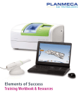
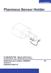
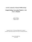
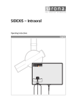
QBION ORAL RADIOLOGY
PACKAGE
User manual
PERIAPICAL
Contents
Program overview..............................................................................................................2
Interaction training............................................................................................................4
Interaction training/Beam (AutoAim)...........................................................................5
Interaction training/Detector..........................................................................................7
Interaction training/Aiming device................................................................................9
Skill training....................................................................................................................11
Explore.........................................................................................................................12
Explore/Beam (AutoAim).......................................................................................13
Explore/Focal spot...................................................................................................16
Explore/Detector......................................................................................................19
Explore/Aiming device............................................................................................22
Expose.........................................................................................................................25
Expose/Beam (AutoAim)........................................................................................26
Expose/Beam...........................................................................................................29
Expose/Beam and detector......................................................................................33
Error analysis...............................................................................................................37
Error analysis/Beam (AutoAim)..............................................................................38
Error analysis/Beam ...............................................................................................41
Error analysis/Beam and detector............................................................................45
Qbion AB© 2010-05
2
Program overview
Periapical is one of four programs in the Qbion Oral Radiology Package (QORP). The
overall aim of the program is to provide an environment for skill training in periapical
radiography without the use of ionising radiation. Training is accomplished by
performance and analysis of radiographic examinations of a virtual patient.
Start the program by clicking on the PERIAPICAL icon.
The Standard edition of the program contains the two modules “Interaction training”
and “Skill training”.
Simulator training philosophy
Radiology simulator training is performed in a radiation-free environment.
Radiographic examinations can therefore be repeated without any radiation risks. By
adding features normally not available in the real world learning can be improved.
Look in the x-ray beam direction
Prior to any intraoral radiographic examination, the oral cavity must be examined in
order to find the proper horizontal and vertical angulation of the tube head and the
detector position. Viewing the patient in the planned x-ray beam direction and then
pointing the aiming device in the same direction will align the x-ray correctly.
Skill training exercises where the tube head is to be positioned (Expose and Error
analysis) start with displaying only the patient and the detector. Tube head is not
visualised. Instead the user should turn the patient to a position where he/she looks at
the patient in the planned x-ray beam direction. After proceeding, the tube-head is
visualised and the task continues.
Qbion AB© 2010-05
3
Interaction training
The aim with the interaction training
module is to acquire skills with which to
navigate in and interact with the virtual
environment (VE) where the radiology
skill training is performed. The module is
comprised of three separate exercises
which are designed for the acquisition of
interaction skills necessary for successful
performance of the exercises in the skill
training module. The exercises are
“Beam (AutoAim)”, ”Detector”, and
“Aiming device”.
It is highly recommended that the
exercises in the interaction training
module are done before entering the skill
training module.
Repeat the exercises as many times as needed until you can easily control the tools
for navigation and interaction!
The effect of skill training will be jeopardised if interaction training is neglected.
Navigation and interaction
User interface components and how to navigate in and interact with the VE are
described in a separate manual called “Qbion Oral Radiology Package, User manual,
General information”.
Qbion AB© 2010-05
4
Interaction training/Beam (AutoAim)
Brief presentation of the exercise
AutoAim: Central ray is automatically directed towards the middle of the detector. The
central ray keeps hitting the middle of the detector even when x-ray tube head (focal
spot) or detector is moved in any direction.
The VE presents a scene with a patient
model, an x-ray tube head, and a detector
in random positions for intraoral imaging.
The central ray is visualised as a blue line
that hits the middle of the detector. A
white line with a different inclination
crosses the blue line on the detector
surface.
The tube head can be moved up/down
and sideways with the conventional
mouse. The central ray is fixed to the
centre of the detector independent of the
tube head movement (AutoAim). The scene is controlled with the interaction tools and
the tube head with the conventional mouse (right button).
TASK
The task is to move the tube head so the blue and white lines coincide. A beep indicates
when the task is completed. The time for completion of the task is presented in the
dialogue window.
Hint 1: “Grasp” the back of the tube head
housing and move it. The central ray is
always directed against the middle of the
detector.
Hint 2: The task is easier to complete by
zooming out with the navigation tools so the
complete tube head is visible.
Qbion AB© 2010-05
5
The exercise step-by-step
1. Select: “Interaction training” in the program menu
2. Select:
Beam (AutoAim)
3. Use the navigation tools to change the view of
the scene so that you can see the relation
between the blue central ray from the x-ray tube
head and the white line from different directions.
4. Use the conventional mouse (right button) to
position the x-ray tube head so the blue central
ray coincide with the corresponding white line
5. A beep indicates a successful attempt.
Short instructions and feedback are presented in the
dialogue window.
Qbion AB© 2010-05
6
Interaction training/Detector
Brief presentation of the exercise
The VE presents a scene with a patient
with a detector positioned inside the
mouth. The detector is randomly
positioned in the vicinity of the dental
arches. A white frame, slightly larger
than the detector, is displayed in the
vicinity of the detector.
The distance between the tooth arch and
the detector can be changed, and the
detector can be tilted. Clicking right or
middle mouse button (depending on
viewing direction) causes a horizontal
shift of detector position. Tilting is
performed with the left mouse button as a
rotation along a horizontal line in the
detector plane.
TASK
The task is to move the detector into the white frame by means of the conventional
mouse. A sound signal indicates when the task is completed. The time for completion of
the task is presented in the dialogue window.
Hint: The detector is tilted with left mouse
button and moved horizontally by the right or
middle mouse buttons.
Qbion AB© 2010-05
7
The exercise step-by-step
1. Select: “Interaction training” in the program
menu
Select:
Detector
3. Use the navigation tools to change the view of
the scene if needed.
4. Use the conventional mouse (right, middle, and
left button) to position the detector into the
white frame.
5. When you have succeeded, you will hear a
beep.
Short instructions and feedback are presented in
the dialogue window.
Qbion AB© 2010-05
8
Interaction training/Aiming device
Brief presentation of the exercise
The VE presents a scene with a patient
and tube head. A detector is positioned
inside the mouth. The aiming device is
pointed in a random direction.
When changing the direction, the tube
head rotates around the focal spot.
Movement of the aiming device is
performed with the left mouse button.
TASK
The task is to move and direct the aiming device toward the detector so an imaginary xray beam covers the entire detector area. A beep sounds signal when the task is
completed. The time for completion of the task is presented in the dialogue window.
Hint 1: “Grasp” the aiming device and direct it toward the detector.
Hint 2 Tube head housing rotates around the focal spot, which has a fixed position.
Hint 3: Look along the aiming device towards the detector to find the appropriate direction.
Hint 4: Try viewing the scene from different directions and distances.
Qbion AB© 2010-05
9
The exercise step-by-step
1. Select: “Interaction training” in the program
menu
2. Select:
Aiming device
3. Use the navigation tools to change the view of
the scene if needed.
4. Use the conventional mouse (right button) to
direct the aiming device over the detector.
5. The aiming device shall be directed so that an
imaginary x-ray beam covers the entire
detector area.
6. When you have succeeded a beep is heard.
Short instructions and feedback are presented in
the dialogue window.
Qbion AB© 2010-05
10
Skill training
The aim of the skill training module is to
acquire the skills to perform high quality
periapical radiography examinations and
to analyse and interpret projection errors.
The skill training is organised under the
following three headings
• Explore
• Expose
• Error analysis
The “Explore” exercises demonstrate
how radiographic depiction is changed
when single projection parameters are
altered. The exercises under the headings
“Expose” and Error analysis” present
tasks with clearly defined goals. The
user’s performance is evaluated and the
simulator presents immediate feedback.
Thorough investigation of the content in each exercise is recommended. There are no
restrictions concerning training order.
AutoAim
This function directs the central ray automatically towards the middle of the detector.
The central ray keeps hitting the middle of the detector even when x-ray tube head
(focal spot) or detector is moved in any direction.
Qbion AB© 2010-05
11
Explore
General information
The exercises under this heading aim to demonstrate how changes in projection
parameters such as x-ray beam direction and detector positioning influence radiographic
depiction.
There are four exercises called “Beam (AutoAim)”, “Focal spot”, “Aiming device”, and
“Detector”. In order to refine the exercises each one is designed to deal only with
changes in a single projection parameter.
Before exploring an exercise the area to be examined must be selected. All exercises
start by displaying the scene with the patient model, a tube head, and a detector
positioned for a periapical radiograph of the selected area. In addition two identical
radiographs, rendered from the individual positions of the detector and tube head
relative to the patient, are displayed. One radiograph is fluoroscopically displayed.
When projection changes are made the fluoroscopic image is continuously updated. One
can therefore follow how changes in a projection parameter influences the radiographic
depiction in real-time. Push the “LookThrough” button to enter LookThrough mode.
LookThrough
In this mode the user looks at the patient from the focal spot through the aiming device.
The tube head housing is in the same position as it was before entering LookThrough
mode. This implies that viewing direction is identical with x-ray beam direction.
The teeth are displayed as a transparent mesh, giving an illusion of the radiographic
depiction, which can be compared with the fluoroscopically displayed radiograph.
Return to ordinary viewing mode by pushing the “Exit LookThrough” button. The x-ray
beam direction is the same as it was before exiting LookThrough mode.
Qbion AB© 2010-05
12
Explore/Beam (AutoAim)
Purpose
To demonstrate how the radiographic depiction is influenced by changes in x-ray beam
direction.
Brief presentation of the exercise
The tube head can be moved up/down and sideways. Tube head movement and
radiographic depiction is synchronised. The influence of changes in beam direction on
radiographic depiction can therefore be followed in real-time.
In LookThrough mode, using the navigation tools changes the viewing direction.
AutoAim: Central ray is automatically directed towards the middle of the detector. The
central ray keeps hitting the middle of the detector even when x-ray tube head (focal
spot) or detector is moved in any direction.
The exercise step-by-step
The simulator exposes two identical radiographs. One radiograph is fluoroscopically displayed,
and is synchronised with tube head movements. By moving the tube head, you can follow how
radiographic depiction is influenced by changes in beam direction.
1. Select: “Skill training” and then
“Explore” in the program menu.
2. Select area to be examined
Right
Left
Upper
O Molar
O Premolar
O Canine
O Incisor
O Canine
O Premolar
O Molar
Lower
O Molar
O Premolar
O Canine
O Incisor
O Canine
O Premolar
O Molar
Qbion AB© 2010-05
13
3. Select:
Beam
(AutoAim)
4. Starting position
The exercise starts with the tube head aligned for an orthoradial projection of the selected area.
Two identical radiographs are presented. Image 1 (gray frame) is the resulting orthoradial
radiograph and Image 2 (white frame) is fluoroscopically displayed.
Use the navigation tools to change the position of the scene to any desired view. Brief
instructions are presented in the instruction and feedback window.
Qbion AB© 2010-05
14
5. Task
Investigate how radiographic depiction is influenced by changes in beam direction. Change
beam direction by moving the tube head. Image 2 (white frame) is continuously updated and
synchronised with tube head movement. Follow the changes in radiographic depiction.
Hint 1:” Grasp” the back of the tube head housing and move it in any direction. Image 2 is
continuously updated.
Hint 2: The task is easier to complete by zooming out with the navigation tools so the complete
tube head is visible.
6. LookThrough
In this mode the patient is viewed from the focal spot. The field of view is restricted by the
aiming device. Viewing direction is identical with the x-ray beam direction used when
LookThrough mode was entered. Change viewing direction with the navigation tools. Image 2
(white frame) is continuously updated and synchronised with viewing position (focal spot).
Follow the changes in radiographic depiction.
Hint: Change viewing position with the tools you normally use for scene movement.
7. Return to ordinary viewing mode
Push the “Exit LookThrough” button to return to ordinary viewing mode. The exercise continues
in the same mode as it started. X-ray beam direction is the same as it was before exiting
LookThrough mode.
Qbion AB© 2010-05
15
Explore/Focal spot
Purpose
To demonstrate how the radiographic depiction is influenced by changes in focus
position (tube head position) without change in beam direction.
Brief presentation of the exercise
The tube head can be moved up/down and sideways. Tube head movement and
radiographic depiction is synchronised. The influence of changes in focus position
without simultaneous alignment of the aiming device towards the detector on
radiographic depiction can therefore be followed in real-time.
In LookThrough mode, using the navigation tools changes the viewing direction.
The exercise step-by-step
The simulator exposes two identical radiographs. One radiograph is fluoroscopically displayed.
The fluoroscopically displayed radiograph is synchronised with tube head movements. By
moving the tube head you can follow how radiographic depiction is influenced by changes in
focus position.
1. Select: “Skill training” and then
“Explore” in the program menu.
2. Select area to be examined
Right
Left
Upper
O Molar
O Premolar
O Canine
O Incisor
O Canine
O Premolar
O Molar
Lower
O Molar
O Premolar
O Canine
O Incisor
O Canine
O Premolar
O Molar
Qbion AB© 2010-05
16
3. Select:
Focal spot
4. Starting position
The exercise starts with the tube head aligned for an orthoradial projection of the selected area.
Two identical radiographs are presented. Image 1 (gray frame) is the resulting orthoradial
radiograph and Image 2 (white frame) is fluoroscopically displayed.
Use the navigation tools to change the position of the scene to any desired view. Brief
instructions are presented in the instruction and feedback window.
Qbion AB© 2010-05
17
5. Task
Investigate how radiographic depiction is influenced by changes in focus position (tube head
position). Change focus position by moving the tube head in any desired direction. Image 2
(white frame) is continuously updated and synchronised with tube head movement. Follow the
changes in radiographic depiction.
Hint 1: “Grasp” the back of the tube head housing and move it in any direction. Image 2 is
continuously updated.
Hint 2: The task is easier to complete by zooming out with the navigation tools so the complete
tube head is visible.
6. LookThrough
By pressing the “LookThrough” button LookThrough mode is entered. In this mode the patient is
viewed from the focal spot. The field of view is restricted by the aiming device. The viewing
direction is identical with the x-ray beam direction used before entering LookThrough mode. Use
the navigation tools to move tube head. Image 2 (white frame) is continuously updated and
synchronised with tube head movement. Follow the changes in radiographic depiction.
Hint: Move the tube head with the tools you normally use for scene movement.
7. Return to ordinary viewing mode
Push the “Exit LookThrough” button to return to ordinary viewing mode. The exercise continues
in the same mode as it started. The tube head has the same position as before exiting
LookThrough mode.
Qbion AB© 2010-05
18
Explore/Detector
Purpose
To demonstrate how the radiographic depiction is influenced by changes in detector
position.
Brief presentation of the exercise
The detector can be moved horizontally and be tilted. Tube head position is fixed.
Horizontal movement of the detector causes changes in focus-detector-distance.
Detector is tilted along a horizontal line in the detector plane. Detector movement and
radiographic depiction is synchronised. The influence of changes in detector position on
radiographic depiction can therefore be followed in real-time. Unexposed detector areas
are displayed in blue colour in rendered radiographs.
The exercise step-by-step
The simulator exposes two identical radiographs. One radiograph is fluoroscopically displayed
and is synchronised with tube head movements. By moving the detector you can follow how
radiographic depiction is influenced by changes in detector position.
1. Select: “Skill training” and then
“Explore” in the program menu.
2. Select area to be examined
Right
Left
Upper
O Molar
O Premolar
O Canine
O Incisor
O Canine
O Premolar
O Molar
Lower
O Molar
O Premolar
O Canine
O Incisor
O Canine
O Premolar
O Molar
Qbion AB© 2010-05
19
3. Select:
Detector
4. Starting position
The exercise starts with the tube head aligned for an orthoradial projection of the selected area.
Two identical radiographs are presented. Image 1 (gray frame) is the resulting orthoradial
radiograph and Image 2 (white frame) is fluoroscopically displayed.
Use the navigation tools to change the position of the scene to any desired view. Brief
instructions are presented in the instruction and feedback window.
Qbion AB© 2010-05
20
5. Task
Investigate how radiographic depiction is influenced by changes in detector position. Detector
position is changed by interaction with the conventional mouse. Image 2 (white frame) is
continuously updated and synchronised with tube head movement. Follow the changes in
radiographic depiction.
Hint: The detector is moved horizontally with right (or middle) mouse button and tilted with left
mouse button.
6. LookThrough
In this mode the patient is viewed from the focal spot. The field of view is restricted by the
aiming device. Detector position is the same as it was before entering LookThrough mode.
Move the detector with the mouse. Image 2 (white frame) is continuously updated and
synchronised with detector movement. Follow the changes in radiographic depiction.
Hint: The detector is moved horizontally with right (or middle) mouse button and tilted with left
mouse button.
7. Return to ordinary viewing mode
Push the “Exit LookThrough” button to return to ordinary viewing mode. The exercise continues
in the same mode as it started. Detector position is the same as it was before exiting
LookThrough mode.
Qbion AB© 2010-05
21
Explore/Aiming device
Brief presentation of the exercise
The aiming device can be pointed in any direction. Focal spot position is fixed during
aiming device movement. Aiming device movement and radiographic depiction is
synchronised. The influence of changes in beam direction on radiographic depiction can
therefore be followed in real-time. Unexposed detector areas are displayed in blue
colour in the rendered radiograph.
In LookThrough mode, the viewing direction is changed by using the navigation tools.
The exercise step-by-step
Purpose: To demonstrate how the radiographic depiction is influenced by changes in
beam direction without any changes in focal spot position.
The simulator exposes two identical radiographs. One radiograph is fluoroscopically displayed.
The fluoroscopically displayed radiograph is synchronised with tube head movements. By
moving the tube head you can follow how radiographic depiction is influenced by changes in
beam direction.
1. Select: “Skill training” and then
“Explore” in the program menu.
2. Select area to be examined
Right
Left
Upper
O Molar
O Premolar
O Canine
O Incisor
O Canine
O Premolar
O Molar
Lower
O Molar
O Premolar
O Canine
O Incisor
O Canine
O Premolar
O Molar
Qbion AB© 2010-05
22
3. Select:
Aiming
device
4. Starting position
The exercise starts with the tube head aligned for an orthoradial projection of the selected area.
Two identical radiographs are presented. Image 1 (gray frame) is the resulting orthoradial
radiograph and Image 2 (white frame) is fluoroscopically displayed.
Use the navigation tools to change the position of the scene to any desired view. Brief
instructions are presented in the instruction and feedback window.
Qbion AB© 2010-05
23
5. Task
Investigate how radiographic depiction is influenced by changes in beam direction without any
changes in focal spot position. Change beam direction by moving the aiming device in any
desired direction. Tube head housing rotates around the focal spot. Image 2 (white frame) is
continuously updated and synchronised with tube head movement. Follow the changes in
radiographic depiction (“cone cut”) as the aiming device moves around.
Hint 1: “Grasp” the aiming device and move it in any direction. Tube head housing rotates
around the focal spot. Image 2 is continuously updated.
Hint 2: The task is easier to complete by zooming out with the navigation tools so the complete
tube head is visible.
6. LookThrough
In this mode the patient is viewed from the focal spot. The field of view is restricted by the
aiming device. Viewing direction is identical with x-ray beam direction used when LookThrough
mode was entered. Change viewing direction by moving the tube head with the navigation tools.
Image 2 (white frame) is continuously updated and synchronised with tube head movement.
Follow the changes in radiographic depiction (“cone cut”) as the aiming device moves around.
Hint: Move the aiming device with the tools you normally use for scene movement.
7. Return to ordinary viewing mode
Push the “Exit LookThrough” button to return to ordinary viewing mode. The x-ray beam
direction is the same as it was before exiting LookThrough mode.
Qbion AB© 2010-05
24
Expose
General information
The aim is to acquire skill in exposing correctly projected periapical radiographs. For
that purpose three exercises with rising difficulty are available. The exercises are “Beam
(AutoAim)”, “Beam”, and Beam and detector”. Each exercise can be performed either
in Ordinary mode or in Fluoroscopic mode. Ordinary mode resembles the way
radiographic exams are performed in real situations. In fluoroscopic mode the task is
made easier as the user can continuously follow changes in radiographic depiction
based on adjustments influencing the radiographic image.
All exercises start by displaying a patient and an intraorally positioned detector. In
addition, a correctly projected periapical radiograph, exposed over a randomly chosen
area, is presented as a reference. The task for the user is to duplicate the reference
radiograph by positioning the object or objects (for example tube head, aiming device,
and detector) influencing the radiographic projection to achieve the same result.
The position of the focal spot (from which the x-ray beam emanates) for the radiograph
which shall be exposed is always situated along the central ray of the user’s viewing
direction upon the patient. When preparing an exposure of a radiograph the user
therefore has to adjust the viewing direction to find the proper position of the focal spot.
Changing viewing direction causes a synchronised change in focal spot position.
In fluoroscopic mode, the user gets immediate feedback of projection changes in a
separate window. In ordinary mode no fluoroscopic guidance is available. Exposing
radiographs in ordinary mode resembles the clinical conditions at a radiographic exam.
Task performance is easier in fluoroscopic mode.
The exercises have defined goals. If the image exposed by the user departs too much
from the ideal projection parameters, it has to be corrected.
Qbion AB© 2010-05
25
Expose/Beam (AutoAim)
Brief presentation of the exercise.
AutoAim: Central ray is automatically directed towards the middle of the detector. The
central ray keeps hitting the middle of the detector even when x-ray tube head (focal
spot) or detector is moved in any direction.
A correctly projected periapical radiograph is presented as a reference image. The
radiograph is exposed over a randomly chosen area. The task is to expose a new
radiograph identical with the reference image. The user therefore has to deduce the
beam direction based on an analysis of how the anatomical details are depicted in the
reference image. Detector position for the reference radiograph is displayed in the
scene. AutoAim is active.
The proper x-ray beam direction is established by turning the scene to a position where
you look upon the patient in the same direction as the x-ray beam direction used for
exposing the reference radiograph.
Expose the radiograph by pressing the “Expose” button. The exposed radiograph is
displayed in “Image 3”.
Evaluation: Beam direction (central ray) used for the reference radiograph is visualised
as a white line. The white ball on the line represents the focal spot. The blue line
represents the central ray in your radiograph and the blue ball the focal spot position.
Feedback is given as visual comparison and as angulation error. If the error is too great,
the user must correct it before the exercise is complete.
The exercise can be performed in fluoroscopic mode or in ordinary mode. In
fluoroscopic mode a fluoroscopically displayed radiograph is presented in Image 2
during the whole exercise. The x-ray beam direction in fluoroscopic mode is identical
to, and synchronised with, the users viewing direction. This function facilitates finding
the correct projection.
In ordinary mode no fluoroscopically displayed radiograph is available.
The exercise step-by-step
Purpose: To acquire skill in exposing correctly projected periapical radiographs.
The task is to create a correctly projected radiograph identical to a reference image. The
exercise can be performed in either fluoroscopic mode or in ordinary mode as described
above. The following information describes the exercise in ordinary mode. In fluoroscopic mode,
an additional fluoroscopically displayed radiograph is presented in “Image 2”.
Qbion AB© 2010-05
26
1. Select: “Skill training” in the program
menu
2. Select “Expose”
3. Select “Beam (AutoAim)”
4. Starting position
A patient and a detector are presented at the scene. The reference radiograph, which is a
correctly projected periapical radiograph, is presented in “Image 1” (gray frame).
Use the navigation tools to change the position of the scene to any desired view. Brief
instructions are presented in the instruction and feedback window.
5. Task
Try to duplicate the reference radiograph in “Image 1”.
Qbion AB© 2010-05
27
Start the exercise by adjusting the x-ray beam direction. X -ray beam direction for a radiograph
to be exposed is identical with the direction the patient is viewed. Turn the scene to look at the
patient in the same direction the x-ray beam direction pointed when the reference radiograph
was exposed. The detector is correctly positioned and cannot be moved.
Hint 1: The x-ray beam direction is identical to the viewing direction.
Hint 2: Use the tools for scene movement to change viewing direction.
Expose your radiograph by pressing the “Expose” button. The exposed radiograph is presented
as “Image 3” (blue frame). The central ray and focal spot for the reference radiograph are
displayed as a white line and a white ball, respectively. The central ray and focal spot for the
radiograph you exposed (blue line and blue ball) are visualised inside the tube head housing.
6. Evaluation
Observe the differences in radiographic depiction between the reference radiograph and the
one you exposed.
Any difference in beam direction between your and the reference radiograph is presented under
the evaluation heading. If the error is too great, beam direction has to be adjusted before the
task is complete.
Hint 1: “Grasp” and move the back of the tube head housing. The central ray is always directed
towards the middle of the detector when tube head is moved (AutoAim).
Hint 2: The task is easier to complete by zooming out with the navigation tools so the complete
tube head is visible.
Hint 3: Beam direction: Angle error is calculated as the angle between the central ray when the
reference radiograph was exposed (represented by the white line) and a line between the blue
focal spot and the middle of the detector.
Qbion AB© 2010-05
28
Expose/Beam
Brief presentation of the exercise.
A correctly projected reference periapical radiograph is presented. The radiograph is
exposed over a randomly chosen area. The task is to expose a new periapical radiograph
identical to the reference radiograph. The user therefore has to deduce the projection
parameters for the reference radiograph based on an analysis of how the teeth are
depicted in the reference image. Detector position for the reference radiograph is
displayed in the scene.
In this exercise, the x-ray beam direction is transferred to the virtual environment in a
two step procedure.
•
Positioning the focal spot (from which the x-ray beam emanates). The focal spot
is always situated along the central ray of the viewing direction upon the patient.
Therefore the patient must be turned to a position where you look upon the
patient in the same direction as the x-ray beam direction used for the reference
radiograph.
•
Directing the aiming device towards the detector so the collimated x-ray beam
hits the detector. When moving the aiming device, focal spot position is fixed.
Expose your radiograph by pressing the “Expose” button. The exposed radiograph is
displayed in “Image 3”.
Evaluation: Beam direction (central ray) used for the reference radiograph is visualised
as a white line. The white ball on the line represents the focal spot. The blue line
represents the central ray in your radiograph and the blue ball the focal spot position.
Feedback is given as visual comparison and as angulation error. If an error is too great,
the user must correct it before the exercise is complete.
The exercise can be performed in fluoroscopic mode or in ordinary mode. In
fluoroscopic mode a fluoroscopically displayed radiograph is presented in Image 2
during the whole exercise. The x-ray beam direction in fluoroscopic mode is identical
to, and synchronised with, the users viewing direction. This function facilitates finding
the correct projection.
In ordinary mode no fluoroscopically displayed radiograph is available.
The exercise step-by-step
Purpose: To acquire skill in exposing correctly projected periapical radiographs.
The task is to create a correctly projected periapical radiograph identical to a reference image.
The exercise can be performed in either fluoroscopic mode or in ordinary mode as described
above. The following information describes the exercise in ordinary mode. In fluoroscopic
mode, an additional fluoroscopically displayed radiograph is presented in “Image 2”.
Qbion AB© 2010-05
29
1. Select: “Skill training” in the program menu
2. Select “Expose”
3. Select “Beam”
4. Starting position
A patient and a detector are presented in the scene. The detector is correctly positioned for the
reference radiograph. The reference radiograph, which is a correctly projected periapical
radiograph, is presented in “Image 1” (gray frame).
Use the navigation tools to change the position of the scene to any desired view. Brief
instructions are presented in the instruction and feedback window.
Qbion AB© 2010-05
30
5. Task
Try to duplicate the reference radiograph in “Image 1”.
Start the exercise by adjusting the x-ray beam direction. X -ray beam direction for a radiograph
to be exposed is identical with the direction the patient is viewed. Turn the scene so you can
look at the patient in the same direction the x-ray beam had when the reference radiograph was
exposed. By pressing the “Proceed” button, the x-ray tube head becomes visible. The focal spot
is positioned along the viewing direction in the previous step.
Hint 1: The x-ray beam direction is identical with the viewing direction.
Hint 2: Use the tools for scene movement to change viewing direction.
The aiming device is directed in a random direction, and must now be directed towards the
detector for exposure of a radiograph without any cone cut. The focal spot remains in its original
position when aiming device direction is adjusted.
Hint 1: “Grasp” the aiming device and direct it against the detector.
Hint 2: Tube head housing rotates around the focal spot, which has a fixed position.
Hint 3: Look along the aiming device towards the detector to find the appropriate direction.
Hint 4: Try viewing the scene from different angles and distances.
The “Back” button returns to starting view. X-ray beam direction can be readjusted.
Expose your radiograph by pressing the “Expose” button. The exposed radiograph is presented
as “Image 3” (blue frame). The central ray and focal spot for the reference radiograph are
displayed as a white line and a white ball, respectively. The central ray and focal spot for the
radiograph you exposed (blue line and blue ball) are visualised inside the tube head housing.
Qbion AB© 2010-05
31
6. Evaluation
Observe the differences in radiographic depiction between the reference radiograph and the
one you exposed. Unexposed areas (cone cuts) are represented as blue fields on the
radiograph.
Any differences in projection parameters between your radiograph and the reference radiograph
are presented under the evaluation heading. If an error is too great, the parameter must be
adjusted before the task is completed.
Hint 1: Adjusting beam direction (focal spot position): “Grasp” the back of the tube head
housing and move it until the tube head focal spot (blue ball) coincides with the focal spot
position for the reference radiograph (white ball).
Hint 2: Beam direction: Angle error is calculated as the angle between the central ray when the
reference radiograph was exposed (represented by the white line) and a line between the blue
focal spot and the middle of the detector.
Hint 3: Adjusting aiming device. “Grasp” the aiming device and redirect it until tube head central
ray (blue line) coincides with the central ray for the reference radiograph projection (white line).
Qbion AB© 2010-05
32
Expose/Beam and detector
Brief presentation of the exercise.
A correctly projected reference periapical radiograph is presented. The radiograph is
exposed over a randomly chosen area. The task is to expose a new periapical radiograph
identical to the reference radiograph. The user therefore has to deduce the projection
parameters (detector position and x-ray beam direction) for the reference radiograph,
based on an analysis of how the teeth are depicted in the reference image.
In this exercise three projection parameters are to be transferred to the virtual
environment.
•
Positioning the detector.
•
Positioning the focal spot (from which the x-ray beam emanates). The focal spot
is always situated along the central ray of the viewing direction upon the patient.
Therefore the patient must be turned to a position where you look upon the
patient in the same direction as the x-ray beam direction used for the reference
radiograph.
•
Directing the aiming device towards the detector so the collimated x-ray beam
hits the detector. When moving the aiming device, focal spot position is fixed.
Expose your radiograph by pressing the “Expose” button. The exposed radiograph is
displayed in “Image 3”.
Evaluation: The beam direction (central ray) used for the reference radiograph is
visualised as a white line. The white ball on the line represents the focal spot. The blue
line represents the central ray in your radiograph and the blue ball the focal spot
position.
Feedback is given as visual comparison and as angulation error. If the error is too great,
the user must correct it before the exercise is complete.
The exercise can be performed in fluoroscopic mode or in ordinary mode. In
fluoroscopic mode a fluoroscopically displayed radiograph is presented in Image 2
during the whole exercise. The x-ray beam direction in fluoroscopic mode is identical
to, and synchronised with, the users viewing direction. This function facilitates finding
the correct projection.
In ordinary mode no fluoroscopically displayed radiograph is available.
The exercise step-by-step
Purpose: To acquire skill in exposing correctly projected periapical radiographs.
The task is to create a correctly projected periapical radiograph identical to a reference image.
The exercise can be performed in either fluoroscopic mode or in ordinary mode as described
above. The following information describes the exercise in ordinary mode. In fluoroscopic
mode, an additional fluoroscopically displayed radiograph is presented in “Image 2”.
Qbion AB© 2010-05
33
1. Select: “Skill training” in the program menu
2. Select “Expose”
3. Select “Beam and detector”
4. Starting position
A patient and a detector are presented in the scene. The detector is randomly positioned. The
reference radiograph, which is a correctly projected periapical radiograph, is presented in
“Image 1” (gray frame).
Use the navigation tools to change the position of the scene to any desired view. Brief
instructions are presented in the instruction and feedback window.
5. Task
Qbion AB© 2010-05
34
Try to duplicate the reference radiograph in “Image 1”. Both detector position and x-ray beam
direction must be adjusted for proper imaging
Start the exercise by adjusting the x-ray beam direction. The x -ray beam direction for the
radiograph to be exposed is identical to the direction in which the patient is viewed. Turn the
scene to a position where you can look at the patient in the same direction the x-ray beam
direction was pointed when the reference radiograph was exposed. Then move the detector to
the position you think it had when the reference radiograph was exposed. Adjustment of beam
direction and detector position can be made at any time before the radiograph is exposed. By
pressing the “Proceed” button, the x-ray tube head becomes visible. The focal spot is positioned
along the viewing direction in the previous step.
Hint 1: When exposing the radiograph, the x-ray beam direction is identical to the viewing
direction.
Hint 2: Use the tools for scene movement to change the viewing direction
Hint 3: The detector is moved horizontally with right (or middle) mouse button and tilted with left
mouse button.
The aiming device is randomly directed, and must now be directed towards the detector for
exposure of a radiograph without any cone cut. Focal spot remains in its original position when
aiming device direction is adjusted.
Hint 1: “Grasp” the aiming device and direct it against the detector.
Hint 2: Tube head housing rotates around the focal spot, which has a fixed position.
Hint 3: Look along the aiming device towards the detector to find the appropriate direction.
Hint 4: Try viewing the scene from different angles and distances.
The “Back” button returns to the starting view. Detector position and x-ray beam direction can
be readjusted.
Qbion AB© 2010-05
35
Expose your radiograph by pressing the “Expose” button. The exposed radiograph is presented
as “Image 3” (blue frame). The central ray and focal spot for the reference radiograph are
displayed as a white line and a white ball, respectively. The central ray and focal spot for the
radiograph you exposed (blue line and blue ball) are visualised inside the tube head housing.
Detector position for the reference radiograph is displayed as a white frame.
6. Evaluation
Observe the differences in radiographic depiction between the reference radiograph and the
one you exposed. Unexposed areas (cone cuts) are represented as blue fields on the
radiograph.
Any differences in projection parameters between your and the reference radiograph are
presented under the evaluation heading. If an error is too great the parameter must be adjusted
before the task is completed.
Hint 1: Adjusting beam direction (focal spot position): “Grasp” the back of the tube head
housing and move it until the tube head focal spot (blue ball) coincides with the focal spot
position for the reference radiograph (white ball).
Hint 2: Beam direction: Angle error is calculated as the angle between the central ray when the
reference radiograph was exposed (represented by the white line) and a line between the blue
focal spot and the middle of the detector.
Hint 3: Adjusting aiming device. “Grasp” the aiming device and redirect it until tube head central
ray (blue line) coincides with the central ray for the reference radiograph projection (white line).
Hint 4: Adjusting detector position: Move the detector to a position inside the white frame.
Qbion AB© 2010-05
36
Error analysis
General information
The aim is to acquire skill in analysing incorrect projected periapical radiographs. The
philosophy behind this section is that skill in analysing projection errors implies good
knowledge in radiographic projection principles. Therefore training in error analysis
will improve knowledge and skill in radiography.
The task is to duplicate erroneously projected periapical radiographs. For that purpose
three exercises with rising difficulty are available. The exercises are “Beam
(AutoAim)”, “Beam”, and Beam and detector”. Each exercise can be performed either
in Ordinary mode or in Fluoroscopic mode. Ordinary mode resembles the way
radiographic exams are performed in real situations. In fluoroscopic mode the task is
made easier as the user can continuously follow changes in radiographic depiction
based on adjustments influencing the radiographic image.
All exercises start by displaying a patient and an intraorally positioned detector. In
addition a reference image is presented which is an erroneously projected periapical
radiograph exposed over a randomly chosen area. The task for the user is to duplicate
the reference radiograph by positioning the object or objects (tube head, aiming device,
and detector) influencing the radiographic projection to achieve the same result.
The position of the focal spot (from which the x-ray beam emanates) for the radiograph
which shall be exposed is always situated along the central ray of the user’s viewing
direction upon the patient. When preparing an exposure of a radiograph the user
therefore has to adjust the viewing direction to find the proper position of the focal spot.
Changing viewing direction causes a synchronised change in focal spot position.
In fluoroscopic mode, the user gets immediate feedback of projection changes in a
separate window. In ordinary mode no fluoroscopic guidance is available. Exposing
radiographs in ordinary mode resembles the clinical conditions at a radiographic exam.
Task performance is easier in fluoroscopic mode.
The exercises have defined goals. If the image exposed by the user departs too much
from the ideal projection parameters, it has to be corrected.
Qbion AB© 2010-05
37
Error analysis/Beam (AutoAim)
Brief presentation of the exercise.
AutoAim: Central ray is automatically directed towards the middle of the detector. The
central ray keeps hitting the middle of the detector even when x-ray tube head (focal
spot) or detector is moved in any direction.
An improperly projected reference radiograph is presented. The radiograph is exposed
over a randomly chosen area. The task is to expose a new radiograph identical to the
reference radiograph. The user therefore has to deduce the beam direction for the
reference radiograph based on an analysis of how the teeth are depicted in the reference
image. Detector position for the reference radiograph is displayed in the scene.
AutoAim is active.
The proper x-ray beam direction is established by turning the scene to a position where
you look upon the patient in the same direction as the x-ray beam direction used for
exposing the reference radiograph.
Expose your radiograph by pressing the “Expose” button. The exposed radiograph is
displayed in “Image 3”.
Evaluation: Beam direction (central ray) used for the reference radiograph is visualised
as a white line. The white ball on the line represents the focal spot. The blue line
represents the central ray in your radiograph and the blue ball the focal spot position.
Feedback is given as visual comparison and as angulation error. If the error is too great,
the user must correct it before the exercise is complete.
The exercise can be performed in fluoroscopic mode or in ordinary mode. In
fluoroscopic mode a fluoroscopically displayed radiograph is presented in Image 2
during the whole exercise. The x-ray beam direction in fluoroscopic mode is identical
to, and synchronised with, the users viewing direction. This function facilitates finding
the correct projection.
In ordinary mode no fluoroscopically displayed radiograph is available.
The exercise step by step
Purpose: To acquire skill in analysing incorrect projected periapical radiographs.
The task is to duplicate an improperly projected periapical radiograph. The exercise can be
performed in either fluoroscopic mode or in ordinary mode, as described above. The following
information describes the exercises in ordinary mode. In fluoroscopic mode, an additional
fluoroscopically displayed radiograph is presented in “Image 2”.
Qbion AB© 2010-05
38
1. Select: “Skill training” in the program menu
2. Select “Error analysis”
3. Select “Beam (AutoAim)”
4. Starting position
A patient and a detector are presented in the scene. The reference radiograph, which is an
incorrectly projected periapical radiograph, is presented in “Image 1” (gray frame).
Use the navigation tools to change the position of the scene to any desired view. Brief
instructions are presented in the instruction and feedback window.
Qbion AB© 2010-05
39
5. Task
Try to duplicate the reference radiograph in “Image 1”.
Start the exercise by adjusting the x-ray beam direction. X -ray beam direction for a radiograph
to be exposed is identical to the direction in which the patient is viewed. Turn the scene to a
position where you can look at the patient in the same direction the x-ray beam direction was
pointed when the reference radiograph was exposed. The detector is correctly positioned and
cannot be moved.
Hint 1: When exposing the radiograph, the x-ray beam direction is identical with the viewing
direction.
Hint 2: Use the tools for scene movement to change viewing direction.
Expose your radiograph by pressing the “Expose” button. The exposed radiograph is presented
as “Image 3” (blue frame). The central ray and focal spot for the reference radiograph are
displayed as a white line and a white ball, respectively. The central ray and focal spot for the
radiograph you exposed (blue line and blue ball) are visualised inside the tube head housing.
6. Evaluation
Observe the differences in radiographic depiction between the reference radiograph and the
one you exposed.
Any difference in beam direction between your and the reference radiograph is presented under
the evaluation heading. If the error is too great, beam direction has to be adjusted before the
task is complete.
Hint 1: “Grasp” and move the back of the tube head housing. The central ray is always directed
towards the middle of the detector when tube head is moved (AutoAim).
Hint 2: The task is easier to complete by zooming out with the navigation tools so the complete
tube head is visible.
Hint 3: Beam direction: Angle error is calculated as the angle between the central ray when the
reference radiograph was exposed (represented by the white line) and a line between the blue
focal spot and the middle of the detector.
Qbion AB© 2010-05
40
Error analysis/Beam
Brief presentation of the exercise.
An improperly projected reference radiograph is presented. The radiograph is exposed
over a randomly chosen area. The task is to expose a new radiograph identical with the
reference radiograph. The user therefore has to deduce the projection parameters for the
reference radiograph based on an analysis of how the teeth are depicted in the reference
image. Detector position for the reference radiograph is displayed in the scene.
In this exercise, the x-ray beam direction is transferred to the virtual environment in a
two step procedure.
•
Positioning the focal spot (from which the x-ray beam emanates). The focal spot
is always situated along the central ray of the viewing direction upon the patient.
Therefore the patient must be turned to a position where you look upon the
patient in the same direction as the x-ray beam direction used for the reference
radiograph.
•
Directing the aiming device towards the detector so the collimated x-ray beam
hits the detector. When moving the aiming device, focal spot position is fixed.
Expose your radiograph by pressing the “Expose” button. The exposed radiograph is
displayed in “Image 3”.
Evaluation: Beam direction (central ray) used for the reference radiograph is visualised
as a white line. The white ball on the line represents the focal spot. The blue line
represents the central ray in your radiograph and the blue ball the focal spot position.
Feedback is given as visual comparison and as angulation error. If an error is too great,
the user must correct it before the exercise is complete.
The exercise can be performed in fluoroscopic mode or in ordinary mode. In
fluoroscopic mode a fluoroscopically displayed radiograph is presented in Image 2
during the whole exercise. The x-ray beam direction in fluoroscopic mode is identical
to, and synchronised with, the users viewing direction. This function facilitates finding
the correct projection.
In ordinary mode no fluoroscopically displayed radiograph is available.
The exercise step-by-step
Purpose: To acquire skill in analysing incorrect projected periapical radiographs.
The task is to duplicate an improperly projected periapical radiograph. The exercise can be
performed in either fluoroscopic mode or in ordinary mode, as described above. The following
information describes the exercises in ordinary mode. In fluoroscopic mode, an additional
fluoroscopically displayed radiograph is presented in “Image 2”.
Qbion AB© 2010-05
41
1. Select: “Skill training” in the program menu
2. Select “Error analysis”
3. Select “Beam”
4. Starting position
A patient and a detector are presented at the scene. The detector is correctly positioned for the
reference radiograph. The reference radiograph, which is an incorrectly projected periapical
radiograph, is presented in “Image 1” (gray frame).
Use the navigation tools to change the position of the scene to any desired view. Brief
instructions are presented in the instruction and feedback window.
Qbion AB© 2010-05
42
5. Task
Try to duplicate the reference radiograph in “Image 1”.
Start the exercise by adjusting the x-ray beam direction. X -ray beam direction for a radiograph
to be exposed is identical to the direction in which the patient is viewed. Turn the scene to a
position where you can look at the patient in the same direction the x-ray beam direction was
pointed when the reference radiograph was exposed. By pressing the “Proceed” button, the xray tube head becomes visible. The focal spot is positioned along the viewing direction in the
previous step.
Hint 1: When exposing the radiograph, the x-ray beam direction is identical with the viewing
direction.
Hint 2: Use the tools for scene movement to change viewing direction.
The aiming device is randomly directed. The aiming device must now be directed towards the
detector for exposure of a radiograph without any cone cut. Focal spot remains in its original
position when aiming device direction is adjusted.
Hint 1: “Grasp” the aiming device and direct it against the detector.
Hint 2: Tube head housing rotates around the focal spot, which has a fixed position.
Hint 3: Look along the aiming device towards the detector to find the appropriate direction.
Hint 4: Try viewing the scene from different angles and distances.
The “Back” button returns to starting view. X-ray beam direction can be readjusted.
Expose your radiograph by pressing the “Expose” button. The exposed radiograph is presented
as “Image 3” (blue frame). The central ray and focal spot for the reference radiograph are
displayed as a white line and a white ball, respectively. The central ray and focal spot for the
radiograph you exposed (blue line and blue ball) are visualised inside the tube head housing.
Qbion AB© 2010-05
43
6. Evaluation
Observe the differences in radiographic depiction between the reference radiograph and the
one you exposed. Unexposed areas (cone cuts) are represented as blue fields on the
radiograph.
Any differences in projection parameters between your radiograph and the reference radiograph
are presented under the evaluation heading. If an error is too great, the parameter must be
adjusted before the task is completed.
Hint 1: Adjusting beam direction (focal spot position): “Grasp” the back of the tube head
housing and move it until the tube head focal spot (blue ball) coincides with the focal spot
position for the reference radiograph (white ball).
Hint 2: Beam direction: Angle error is calculated as the angle between the central ray when the
reference radiograph was exposed (represented by the white line) and a line between the blue
focal spot and the middle of the detector.
Hint 3: Adjusting aiming device. “Grasp” the aiming device and redirect it until tube head central
ray (blue line) coincides with the central ray for the reference radiograph projection (white line).
Qbion AB© 2010-05
44
Error analysis/Beam and detector
Brief presentation of the exercise.
An improperly projected reference radiograph is presented. The radiograph is exposed
over a randomly chosen area. The task is to expose a new radiograph identical to the
reference radiograph. The user therefore has to deduce the projection parameters
(detector position and x-ray beam direction) for the reference radiograph based on an
analysis of how the teeth are depicted in the reference image.
In this exercise three projection parameters are to be transferred to the virtual
environment.
•
Positioning the focal spot (from which the x-ray beam emanates). The focal spot
is always situated along the central ray of the viewing direction upon the patient.
Therefore the patient must be turned to a position where you look upon the
patient in the same direction as the x-ray beam direction used for the reference
radiograph.
•
Positioning the detector.
•
Directing the aiming device towards the detector so the collimated x-ray beam
hits the detector. When moving the aiming device, focal spot position is fixed.
Expose your radiograph by pressing the “Expose” button. The exposed radiograph is
displayed in “Image 3”.
Evaluation: The beam direction (central ray) used for the reference radiograph is
visualised as a white line. The white ball on the line represents the focal spot. The blue
line represents the central ray in your radiograph and the blue ball the focal spot
position.
Feedback is given as visual comparison and as angulation error. If the error is too great,
the user must correct it before the exercise is complete.
The exercise can be performed in fluoroscopic mode or in ordinary mode. In
fluoroscopic mode a fluoroscopically displayed radiograph is presented in Image 2
during the whole exercise. The x-ray beam direction in fluoroscopic mode is identical
to, and synchronised with, the users viewing direction. This function facilitates finding
the correct projection.
In ordinary mode no fluoroscopically displayed radiograph is available.
The exercise step-by-step
Purpose: To acquire skill in analysing incorrect projected periapical radiographs.
The task is to duplicate an improperly projected periapical radiograph. The exercise can be
performed in either fluoroscopic mode or in ordinary mode, as described above. The following
information describes the exercises in ordinary mode. In fluoroscopic mode, an additional
fluoroscopically displayed radiograph is presented in “Image 2”.
Qbion AB© 2010-05
45
1. Select: “Skill training” in the program menu
2. Select “Error analysis”
3. Select “Beam and detector”
4. Starting position
A patient and a detector are presented in the scene. The detector is randomly positioned. The
reference radiograph, which is an incorrectly projected periapical radiograph, is presented in
“Image 1” (gray frame).
Use the navigation tools to change the position of the scene to any desired view. Brief
instructions are presented in the instruction and feedback window.
Qbion AB© 2010-05
46
5. Task
Try to duplicate the reference radiograph in “Image 1”. Both detector position and x-ray beam
direction must be adjusted for proper imaging
Start the exercise by adjusting the x-ray beam direction. The x -ray beam direction for the
radiograph to be exposed is identical to the direction in which the patient is viewed. Turn the
scene to a position where you can look at the patient in the same direction the x-ray beam
direction was pointed when the reference radiograph was exposed. Then move the detector to
the position you think it had when the reference radiograph was exposed. Adjustment of beam
direction and detector position can be made at any time before the radiograph is exposed. By
pressing the “Proceed” button, the x-ray tube head becomes visible. The focal spot is positioned
along the viewing direction in the previous step.
Hint 1: When exposing the radiograph, the x-ray beam direction is identical to the viewing
direction.
Hint 2: Use the tools for scene movement to change the viewing direction
Hint 3: The detector is moved horizontally with right (or middle) mouse button and tilted with left
mouse button.
The aiming device is randomly directed, and must now be directed towards the detector for
exposure of a radiograph without any cone cut. Focal spot remains in its original position when
aiming device direction is adjusted.
Hint 1: “Grasp” the aiming device and direct it against the detector.
Hint 2: Tube head housing rotates around the focal spot, which has a fixed position.
Hint 3: Look along the aiming device towards the detector to find the appropriate direction.
Hint 4: Try viewing the scene from different angles and distances.
The “Back” button returns to the starting view. Detector position and x-ray beam direction can
be readjusted.
Qbion AB© 2010-05
47
Expose your radiograph by pressing the “Expose” button. The exposed radiograph is presented
as “Image 3” (blue frame). The central ray and focal spot for the reference radiograph are
displayed as a white line and a white ball, respectively. The central ray and focal spot for the
radiograph you exposed (blue line and blue ball) are visualised inside the tube head housing.
Detector position for the reference radiograph is displayed as a white frame.
6. Evaluation
Observe the differences in radiographic depiction between the reference radiograph and the
one you exposed. Unexposed areas (cone cuts) are represented as blue fields on the
radiograph.
Any differences in projection parameters between your and the reference radiograph are
presented under the evaluation heading. If an error is too great the parameter must be adjusted
before the task is completed.
Hint 1: Adjusting beam direction (focal spot position): “Grasp” the back of the tube head
housing and move it until the tube head focal spot (blue ball) coincides with the focal spot
position for the reference radiograph (white ball).
Hint 2: Beam direction: Angle error is calculated as the angle between the central ray when the
reference radiograph was exposed (represented by the white line) and a line between the blue
focal spot and the middle of the detector.
Hint 3: Adjusting aiming device. “Grasp” the aiming device and redirect it until tube head central
ray (blue line) coincides with the central ray for the reference radiograph projection (white line).
Hint 4: Adjusting detector position: Move the detector to a position inside the white frame.
Qbion AB© 2010-05
48