1
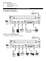
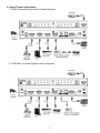
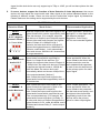
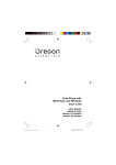
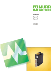
Matrix Switcher
With HDMI® technology
Coaxial & Optical Audio Output
Model: 33-12500
INTRODUCTION
Thank you for your purchase of the Stellar Labs Model 33-12500 Matrix Switcher. This switcher is
designed to simplify the use of multiple high definition A/V devices in a home theater system.
The 33-12500 Matrix Switcher is ideal for Home Theater, gaming room, HTiB (or Sound bar) devices,
and even in public installations such as sports bars and retail displays, anywhere that two video
displays are intended to share multiple high definition sources.
Coaxial and TOSLINK audio outputs are also provided, on video output A, making it simple to
separately send digital audio of the four source devices to a separate audio system, without having to
occupy an HDMI connection.
With the splitter and matrix functions, users can share the same source device to two HD video
devices, or select from the four sources independently.
This unit provides eight different video format detection modes.
user to define the output video and audio format.
Selecting these modes allows the
FEATURES AND CONTENTS
For the best performance of this matrix switch box, please read this manual carefully and keep it for
further information.
Features:
❧
HDMI® 3D video format support
❧
Supports 1080P/12-Bit Deep Color HDTV
❧
Supports Pixel Clock Rate up to 225 MHz
❧
4 inputs and 2 outputs; HDMI full matrix selection
❧
Each output can select different source from one of the 4 inputs (matrix mode)
❧
Both outputs can select from the same input source (splitter mode)
❧
Eight different video detection modes
❧
Output-A supports digital S/PDIF audio output (coaxial & optical)
❧
Supports HDCP 2.0
®
®
❧
DTS HD, Dolby TrueHD lossless compressed digital audio compliant
❧
Gold plated HDMI connectors
❧
IR remote control
❧
Rugged, stylish metal housing design
1
Package Contents
❧
❧
❧
❧
DC 5V/2A power adaptor
IR remote control
4-IN / 2-OUT Matrix switcher
User’s Manual
TYPICAL APPLICATIONS
A. Entertainment Application
(Family Room or Gaming Room)
B. HTiB or Sound Bar Application
(TOSLINK or Coaxial to HTiB or Sound Bar)
2
C. Home Theater Application
1. HDMI Connection to a Home Theater Receiver
2. TOSLINK or Coaxial Digital Audio to Amplifier
3
NOTE:
✔ If you want to select or distribute 3D source to either one or two of the displays, please make
sure all of the sink devices support the same HDMI 3D video format as the source. The 3D
image cannot be delivered to TVs which do not support 3D video format.
✔ Output-A supports an unmodified SPDIF (coaxial/optical) digital audio output. Users can use it
to connect to a Home Theater system which supports a coaxial/optical digital audio input.
✔ The output of the SPDIF (coaxial/optical) digital audio format is based on the HDMI Output-A.
If the sink devices (HDTV or Projector), which connected to Output A and Output B, can only
support stereo audio, the coaxial/optical digital audio may also send out PCM stereo audio.
✔ For audio output format adjustment: (Please refer to the source device manual.)
®
®
1. Check the supported audio format of the feature film. (Stereo, DTS 5.1, and Dolby Digital
5.1...etc)
®
2. Set the audio output format of source device. Ex. uncompressed PCM or Bit Stream (Dolby
®
Digital 5.1, DTS 5.1 ...etc.)
3. Select the output of audio format and language from the main feature menu.
®
✔ For HD quality audio (Dolby TrueHD, DTS-HD Master AudioTM), or other audio formats that
need high bandwidth for audio transmission, please use HDMI connection for the HD audio
transmission.
✔ If the output audio format is not supported by the sink device (HDTV, Home Theater receiver,
Sound Bar Speaker), you may hear noise form the speakers or you will not hear any sound
from the speakers.
✔ If you want to use a Home Theater System or other speaker system for audio output, it is
recommended to mute the audio speaker of the HDTV.
✔ It is recommended all the connected sink devices (HDTV, Projector, Home Theater
Receiver…etc.) and source devices (Blue-ray Player, PS3…etc.) support the same highest
resolution, color deep and audio format.
CONNECTION & OPERATION
Connection
Step 1: Connect the DC 5V power adaptor to the Matrix Switcher.
Step 2: Connect the HDMI cables from the HD sources (PS3, DVD player, Blue-ray Player…etc) to the
input ports of the Matrix Switcher.
Step 3: Connect the HDMI cables from your HD display (HDTV or projector) to the output port (Port A
or Port B) of the Matrix Switcher.
Output Port A supports additional SPDIF digital audio output. If your Home Theater (or Sound
System) doesn’t support HDMI input, you can use a coaxial/optical audio cable to connect the
digital audio to your Home Theater (or Sound System).
Step 4: After you finish the connection, the Active-A (or Active-B) indication LED (red), and input
indication LED (green) will light.
Operation
Matrix Mode:
Individual Selection for each output port
Splitter Mode:
Sharing same HD source to both outputs
A.
If source devices do not support the function of Auto Detection & Auto Adjustment, please
set the output audio and video signal of the source device first, and make sure the setting can be
supported by the sink devices. For example, if user set the source to send out a 1080p video
4
signal, but the sink device can only support up to 720p or 1080i, you will not have picture the sink
device.
B.
If source devices support the function of Auto Detection & Auto Adjustment, the source
device will auto adjust the output audio and video signal to the optimal standard based on the
following 8 different modes. Users can also set the audio/video output signal by themselves.
Please make sure the setting can be supported by the sink devices.
33-12500 Matrix Switcher
Detection Mode
Mode Action
Recommended Application
Select the output audio and video signal to the
highest format which can be supported by both
of the sink devices. (For example, when the
H.C.F. (Highest
sink devices of Output A and Output B support
Common Factor ) different video and audio formats, the highest
※ Preset Mode
format of Output A is 1080p/12-bit & 2
channels, the other sink device of Output B
supports the highest format to 1080i/8-bit & 2
channels, under Mode 1, it will automatically
1 2 3
detect and choose 1080i/8-bit & 2 channels as
the output standard.)
Video: Select the output video signal to the
Mode 2
Video Maximum & highest video format which supported by
Output A or Output B sink devices. (For
Audio H.C.F.
example, the highest video format of Output A
is 1080p/12-bit, the other sink device of Output
B supports the highest format to 1080i/8-bit,
under this Mode, the source device will
1 2 3
automatically detect and choose 1080p/12-bit
as the output standard.) [Notice 1]
Audio: Select the output audio signal to the
highest audio format that supported by both of
the sink devices.
TV wall application, sports bar
application, or other application
that different standard
(Resolution, Color Deep)
HDTVs are connected together.
Video: Select the output video signal to the
highest format that supported by both of the
sink devices (Output A & Output B).
Audio: Select the output audio signal to the
highest audio format which supported by one
of the connected devices. (For example, the
highest audio format of Output A is Dolby 5.1,
the other sink device of Output B supports the
highest format to 2 CH, under this Mode, and it
will detect and choose Dolby 5.1 as the output
standard.)
[Notice 2]
Home Theater application; Two
rooms application; When the
source needs to be presented
with the best sound quality, and
the highest video format that
supported by both of two sink
devices will be the primary
option for video output signal.
Mode 1
Video & Audio
Mode 3
Video H.C.F. &
Audio Maximum
1 2 3
5
Home Theater application; Two
rooms application; When the
source needs to be shown with
the best resolution, and the
audio standard that supported
by both of two sink devices will
be the primary option for audio
output signal.
Mode 4
Video & Audio
Maximum
1 2 3
Select the output video and audio signal to the Home Theater application; Two
highest format that supported by Output A or
rooms application; When the
Output B sink devices. [Notice 3]
source needs to be displayed
with the best resolution and
sound, the highest format will be
chosen for the video & audio
output signal.
Video: Select the output video signal to the
highest format that supported by both of the
sink devices (Output A & Output B).
Audio Specified
Audio: Set the output audio signal as one of
(AAC, Dolby 5.1, the following 4 standards: AAC, Dolby 5.1,
DTS 5.1, and 2 CH) DTS 5.1 or 2 CH. If the audio format of
coaxial/optical cable connected source device
is AAC, the output audio standard will be AAC
as well. [Notice 4]
1 2 3
Home Theater application;
Traditional audio amplifier may
only support Toslink or coaxial
for audio input connection,
please use the Toslink or
Coaxial connector for audio
output connection. Under this
mode, the better sound quality
of amplifier can be designated
as the output audio standard.
Video: Select the output video signal to the
Mode 6
Video Maximum & highest video format which supported by
Output A or Output B sink devices. [Notice 3]
Audio Specified
Audio: Set the output audio signal as one of
(AAC, Dolby 5.1, the following 4 standards: AAC, Dolby 5.1,
DTS 5.1, and 2 CH) DTS 5.1 or 2 CH. If the audio format of
coaxial/optical cable connected source device
is AAC, the output audio standard will be AAC
as well. [Notice 4]
1 2 3
Home Theater application;
Traditional audio amplifier
always used Toslink or coaxial
cable instead of HDMI cable for
connection, under this mode,
the better sound quality of
amplifier can be designated as
the output audio standard.
Mode 5
Video H.C.F. &
Mode 7
Reserved
The mode will remain the same functions as The applications of this mode
Mode 1.
are same as Mode 1.
1 2 3
The highest format of Output A connected
Priority of Output A device will be chosen for the primary output
video and audio signal standard. [Notice 5]
Mode 8
Home Theater application, or
user assigns a primary sink
device by connect it to port 1.
1 2 3
■
HDMI 3D video format
Frame packing
[email protected]/24Hz
[email protected]/60Hz
1280x720p@50Hz
Side-by-Side (Half)
[email protected]/60Hz
1920x1080i@50Hz
6
Top-and-Bottom
[email protected]/24Hz
[email protected]/60Hz
1280x720p@50Hz
Notice:
1. If one of the sink devices does not support the highest video format of the other one, the device
with lower video format will show no image.
2. If one of the sink devices does not support the highest audio format of the other one, the device
with lower audio format will become soundless.
3. If one of the sink devices does not support the highest format of the other one, the device with
lower format will either have no picture or no sound presented.
4. Please make sure the setting of the source device can be supported by the amplifier.
5. If the other sink device of Output B does not support the output standard of Output A, the sink
device of Output B will be displayed either without picture or without sound.
IR Remote Operation
❧
Two sets of power and selection keys are available for Output
A and Output B. The power and selection of Output A and Output B
can be controlled individually.
❧
Output A:
- Use the power key of Output A on the IR remote controller to turn
on the signal transmission of Output A. The power indication
LED (Active-A) of Output A on the front panel will be lighted on.
Press the power key of Output A one more time to turn the
Output A to standby.
- Use number keys to switch between sources.
❧
Output B:
- Use the power key of Output B on the IR remote controller to turn
on the signal transmission of Output B. The power indication
LED (Active-B) of Output B on the front panel will be lighted on.
Press the power key of Output B one more time to turn the
Output B to standby.
- Use number keys to switch between sources.
❧
Reset:
Use the Reset key on the IR remote controller to reset the Matrix Switcher to the initial status.
Manual Operation
❧
❧
❧
-
Output A and Output B have individual source selection and power control key.
Output A:
The “Select/Power” key is a multi-function key.
Power Control: Press the “Select/Power” key for 2 seconds to turn off the power
(Standby); press the “Select/Power” key once to turn on the switcher.
Source Selection: If you want to change the input channel manually, you can press the
“Select/Power” key once. A LED will be lighted up for the channel indication.
Output B:
The “Select/Power” key is a multi-function key.
Power Control: Press the button for 2 seconds to turn off the power (Standby); press the
“Select/Power” key once to turn on the switcher.
Source Selection: If you want to change the input channel manually, you can press the
“Select/Power” key once. A LED will be lighted up for the channel indication.
❧
Reset:
Use the Reset key on the back of the Matrix Switcher to reset the Matrix Switcher to the initial
status.
7
The procedure is a cyclic function
When you select the channel, it will be illustraded by a front panel LED.
TROUBLESHOOTING
1. When there is no picture presented, please:
❧
Make sure the direct connection from the source device to the display device without the
HDMI Switcher is working.
❧
Check all connectors connect well or not.
❧
Check the connecting cable is damaged or not.
❧
Check the power of matrix switcher (or reset the matrix switcher)
2. When there is only picture displayed and without sound:
❧ Check the cable connection to see if it fits properly.
❧ Check your cable to see if it supports video transmission only (DVI) or it is damaged.
❧ HDCP may not match very well at first connection; please reset your matrix switcher.
❧
Do you connect any output to your video recorder? HDCP will lock up audio part.
3. When use a coaxial/optical audio cable to connect the matrix switcher to a Home Theater System,
no sound is delivered by the Home Theater System.
❧
Please check the connection.
❧
The coaxial/optical audio cable needs to be connected to the coaxial/optical audio input port
of the Home Theater System.
❧
The audio input selection of the Home Theater System needs to be selected to a
corresponding coaxial/optical audio input.
❧
Please make sure the output audio format can be supported by the Home Theater System.
®
®
®
If the audio format is in Dolby or DTS format, the Home Theater needs to support Dolby or
®
DTS decoding.
4. When use a coaxial/optical audio cable to connect the matrix switcher to a Home Theater System,
the coaxial/optical audio output only delivers stereo audio signal to the Home Theater System.
❧
Because the HDTV (or Projector) which connected to the Output-A can only support stereo
audio signal, the coaxial/optical audio output will send out the audio signal based on the Output
A.
❧
Please refer to the page 3 for audio output format adjustment.
5. When resolution could not show in 1080p.
❧
Make sure your sources and displays are fully supporting 1080p.
❧
Make sure your HDMI cables are capable of transmitting 1080P video signal.
6. When 3D content could not be shown on your display.
❧
Please make sure your sources and displays are 3D supported devices and also support the
same 3D format.
❧
Please check the play mode of Blue-ray player has been set 3D mode or AUTO mode for
video output.
❧
Please make sure the video content is 3D content.
7. If the presented picture is not a proper 3D image, please check whether the 3D format of your
sources (Blue-ray player, PS3, etc.) and displays (TV or projector) are correct setting.
8. If the presented picture is symmetric, which showed with up and down or right and left symmetric
image, please check whether the TV or projector supports 3D display function and make sure the
function is enabled. If the TV or projector does not support 3D video format, please turn off the 3D
play mode of sources.
8
NOTICE
❧
Manufacturer reserves the right to make changes in the hardware, packaging and any
accompanying documentation without prior written notice.
❧
HDMI, the HDMI Logo and High-Definition Multimedia Interface are trademarks or registered
trademarks of HDMI Licensing LLC in the United States and other countries.
®
❧
33-12500 incorporates HDMI technology.
❧
Trademarks and brand names are the properties of their respective owners.
❧
PS3 is a trademark of Sony Computer Entertainment Inc.
❧
Dolby is a registered trademark of Dolby Laboratories.
❧
DTS is a registered trademark & the DTS logos and Symbol are trademarks of DTS, Inc.
9
WARRANTY
This Stellar Labs device is warranted, by MCM Electronics against defects for a period of 365 days
from the date of purchase. This warranty includes manufacture defects and failure due to normal use
and operation. Failure due to misuse, excessive wear or damage, improper installation or other
external factors is not covered under this warranty. MCM Electronics is not responsible for any
consequential on inconsequential damage to any other unit or component incorporated with this
device. There are no other warranties, express or implied, which extend beyond this unit, and there
are no warranties of fitness for any particular purpose. The warranty does not cover consequential
damage due to defective or improper use of products.
Stellar Labs products are:
Distributed Exclusively by
MCM Electronics
650 Congress Park Drive
Centerville, Ohio 45459
www.mcmelectronics.com
10