1
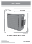
User's manual
30637114.014.2PS
Duct heater
“VENTS NK” series
2
Duct heaters
Introduction ..................................................................................... 3
Application ....................................................................................... 3
Delivery set ...................................................................................... 3
Basic technical data sheet ............................................................. 3
Heater structure .............................................................................. 10
Safety requirements ....................................................................... 18
Installation and operation guidelines........................................ 19
Servicing and maintenance ......................................................... 20
Storage .............................................................................................. 20
Manufacturer's warranty............................................................... 20
Acceptance certificate ................................................................... 21
3
Introduction
This manual combines user's manual, service manual, technical data sheet and installation
guidelines for VENTS NK electric duct heaters, hereinafter referred to as the heater.
Application
Duct electrical heaters are designed for heating of intake fresh air transported through the
ventilating system. The heated air must not contain any combustible or explosive substances,
chemical vapours, dust, soot etc.
The duct heaters are the complete units and are not designed for independent operation.
Delivery set
Duct heater - 1 pce.
User's manual - 1 pce.
Basic technical data sheet
The heaters are available in single- or three-phases modifications.
The heaters are designed for operation in enclosed spaces at the ambient temperature ranging
between -300C up to +500C. Do not heat the air above +400C.
Air flow through the heating coils shall always be above the minimum air flow shown in
tables 2 and 4 to prevent overheating.
Designation key
Number of supply voltage phases
1, 3
Heating coil capacity [kW]
0,6; 0,8; 1,2; 1,6; 1,8; 2,4; 3,4; 3,6; 4,5; 5,1; 6,0; 7,5;
9,0; 10,5; 12,0; 15,0; 18,0; 21,0; 22,5; 24,0; 30,0; 36,0.
Branch pipe diameter for round ducts or
dimensions for rectangular ducts [mm]
100, 125, 150, 160, 200, 250, 315 or
400 200, 500 250, 500 300, 600 300, 600 350
Heater name
NK - duct heater
4
Duct heaters
Designation key example:
NK-315-9,0-3 - three-phase electric heater with branch pipe diameter 315 mm, power 9 kW
NK-600 350-21,0-3 - three-phase electric heater for rectangular duct 600x350 mm, power 21 kW.
The basic heater overall dimensions shall be as shown in tables 1;3 and in fig. 1;2.
The basic heater parameters and thermal dynamic characteristics are shown in tables 2;4.
Fig. 1
Heater
model
NK
NK
NK
NK
NK
NK
NK
NK
NK
NK
NK
NK
NK
NK
NK
NK
Table 1
Dimensions [mm]
5
Heater
model
NK
NK
NK
NK
NK
NK
NK
NK
NK
NK
NK
NK
NK
NK
NK
NK
NK
NK
NK
NK
NK
NK
Table 1
Dimensions [mm]
6
Duct heaters
Heater
model
NK
NK
NK
NK
NK
NK
NK
NK
NK
NK
NK
NK
NK
NK
NK
NK
NK
NK
NK
NK
NK
NK
NK
NK
NK
NK
NK
NK
NK
NK
NK
NK
NK
NK
NK
NK
NK
NK
Table 2
Power
[kW]
Number of
supply voltage
phases [pcs]
Voltage
[V]
Number of
heating elements
x power [kW]
Current
[A]
Min.
air flow
[m3/h]
Weight
[kg]
7
Fig. 2
Heater
model
NK
NK
NK
NK
NK
NK
NK
NK
NK
NK
NK
NK
NK
NK
Table 3
Dimensions [mm]
8
Duct heaters
Heater
model
NK
NK
NK
NK
NK
NK
NK
NK
NK
NK
NK
NK
NK
NK
NK
NK
NK
NK
NK
NK
NK
NK
Table 3
Dimensions [mm]
9
Heater
model
NK
NK
NK
NK
NK
NK
NK
NK
NK
NK
NK
NK
NK
NK
NK
NK
NK
NK
NK
NK
NK
NK
NK
NK
NK
NK
NK
NK
NK
NK
NK
NK
NK
NK
NK
NK
Table 4
Power
[kW]
Number of
supply voltage
phases [pcs]
Voltage
[V]
Number of
Current
heating elements
[A]
x power [kW]
Min.
air flow
[m3/h]
Weight
[kg]
10
Duct heaters
The allowable power supply voltage deviations from the rated value shown in the
tables 2 and 4 shall not exceed +10%.
The ele tric heater has class of insulation I according to the electric shock hazard protection.
Heater structure
The heaters (fig. 3,4) consist of the casing 1 with rigidly fixed connecting box 2 with the removable
cover 3.
The tight seals 4 are located at the external side of the connecting box for routing of supply,
control and ground cables.
The heating elements 5 are located inside the casing.
The casing, the connecting box and the heater cover are made of galvanized steel
The connecting box incorporates fastening and electrical connections for electric heating
elements as well as terminal block for connection to the external supply and control circuits of
the heater;
screw ground terminal;
thermal switches (automatic and manual).
The heaters are equipped with two overheating sensors - thermal switches:
with automatic reset and the temperature threshold value 50° ;
with manual reset and the temperature threshold value 90° ;
Thermal switch with manual reset is equipped with the button for manual restart.
The label RESTART is near the button.
The electric heater wiring diagram is shown at the internal wall of the connecting box.
11
NK heater for round ducts
Fig. 3
NK heater for rectangular ducts
Fig. 4
1 - casing
2 - connecting box
3 - connecting box cover
4 - cable clamps
5 - heating electric element
12
Duct heaters
Wiring diagram type is determined by electrical heating elements quantity, supply voltage and
number of phases in the motor. See the available diagrams in the fig. 5-16.
Designation key:
S1, S2 - thermal switches;
n - electrical heating elements;
X1 - terminal block;
X2 - ground clamp.
Wiring diagram of the electrical heater with one electrical heating element
and single-phase power supply.
Fig. 5
Wiring diagram of the heater with two electrical heating elements and
single-phase power supply.
Fig. 6
13
Wiring diagram of the electric heater with three electrical heating elements and
single-phase power supply.
Fig. 7
Wiring diagram of the heater with three electrical heating elements and
three-phase power supply.
Fig. 8
Fig. 9
Fig. 10
14
Duct heaters
Wiring diagram of the electric heater with three electrical heating elements and
three-phase power supply, star connection and leaded outside thermal
protection contacts.
Fig. 11
Wiring diagram of the electric heater with six electrical heating elements and
three-phase power supply, delta connection and thermal protection contacts
leaded outside.
Fig. 12
15
Wiring diagram of the electrical heater with one electrical heating element,
single-phase power supply and run-out timer.
HEATER
Fig. 13
Wiring diagram of the electric heater with three electrical heating elements,
star connection, three-phase power supply and run-out timer
HEATER
Fig. 14
S - ON\OFF switch
KT - run-out timer
M - fan
KM - magnetic starter
Q - automatic circuit breaker.
16
Duct heaters
Wiring diagram of the rectangular electrical heater with three electrical heating
elements, three-phase power supply and run-out timer.
HEATER
Fig. 15
Wiring diagram of the rectangular electrical heater with three electrical heating
elements, star connection, three-phase power supply and run-out timer.
HEATER
Fig. 16
S - ON\OFF switch
KT - run-out timer
M - fan
KM - magnetic starter
Q - automatic circuit breaker.
17
Check the following conditions before commisioning the device:
realiable grounding (the ground clamp shall be connected to the ground wire);
power to the electrical heater is supplied only when the fan is operating;
electric heater power cut-off is allowed only when the fan is operating, the time span between
the heater power cut-off and the fan turn-off shall be at least 30 min;
minimum air flow through the heating coils shall be equal or more than the value stated in
tables 2 and 4.
Install the fan in the duct before the heater along the air stream direction to disable additional
heating of the electrical heater.
The thermal switches with automatic reset can get actuated during the heater operation.
Such thermal switch turn-on can is posible during abrupt electric power supply cut-off or due to
a wrong heater selection that does not match the set air flow characteristics.
The protecting devices should cut off power supply to the heating elements till the heater
temperature falls down to the threshold value of the thermal switch turning-on.
Turning-on of the thermal switch with manual reset is possible when power is supplied to the
electric heating elements but there is no air flow through the heating coils (emergency operation
mode) or when the air flow is below the required value.
During the thermal switch turm-on:
cut off power supply to the heater;
correct the fault in the ventilation system;
remove the cover from the heater cover by pressing the RESET button,
reset the thermal switch to the reference position.
Fig. 5,6,7,8,9,10,11,12 show the heater wiring diagrams.
Fig. 13,14,15,16 show the recommended wiring diagrams with control circuits.
18
Duct heaters
Operation logic of the electric heaters with control circuits is as follows:
As the ON/OFF switch S turns ON, the KM magnetic starter coil is charged through the closed
contacts of the thernal switches. Consequently electric power to the heating elements is supplied
through the closed contacts of the thermal switches and magnetic starter.
Should at least one of the thermal switches turn on the power circuit of the magnetic starter KM
and respectively, the power circuit of the heating element get broken thus preventing the heater
overheating.
The diagram shows the fan connection example with run-out timer KT when the motor M is turned
off before the heater is turned off to ensure the electric heating elements cooling.
The automatic circuit breaker Q is designed for overload protection of the electrical circuits.
Wiring diagram types are determined by quantity of the heating elements, supply voltage
characteristics, number of phases.
Electric wiring diagrams for round ducts are shown in fig. 5,6,7,8; and for rectangular ducts
in fig. 9,10,11,12.
Safety requirements
The requirements of the present user's manual must be considered during the heater mounting
and operation process as well as the general requirements of and all applicable local and national
building and electrical codes and standards.
Only the qualified electrical engineers authorized for independent execution of the electrical
works for the electrical installations with the voltage up to 1000 V and specially trained to observe
fire and engineering safety regulations are allowed to perform mounting and connection
works of the heater.
The heater shall be grounded.
Power supply to the heater without air supply to the electric heating elements is not allowed.
The heater operation without the thermal switches connected to the external protecting
devices that cut off power supply to the heating elements during the thermal
switches turning on is prohibited.
19
Installation and operation guidelines
Installation, connection, adjustment and repair works shall be performed only after the fan is
disconnected from power supply network.
Before connecting the heater to power supply network, please make sure that the heater is free
of any visible damages and that the electric heating elements are firmly fixed to the casing.
The heater shall be installed in the air duct with the same diameter.
The heater operating position shall provide free access to the connecting box and to the thermal
switch manual RESET button.
The heater shall be firmly fixed but free access for the heater maintenance shall be provided.
The rectangular heaters shall be installed in the air supply system in such a way that pointer on
the heater matches the air motion direction.
The minimum distance between the fan and the heater shall be 1m.
Do not use the thermal insulation materials for the heater insulation.
Content of any flammable and explosive, fire-hazardous materials in the air at the distance of
150 mm or less to the heater and 500 mm or less from the heater inlet/outlet is prohibited.
The air ducts and the fans shall be equipped with the grille or other protecting devices to prevent
free access to the heating elements.
Power shall be supplied through the switch that opens all the phases with the clearance between
the open contacts no less 3mm at all poles in compliance with the electric wiring installation
requirements.
The air filter shall be installed before the heater to protect it from dust and dirt.
The distance between the filter and the heater shall be long enough as the close filter location
to the heater is not allowed due to safety precaution reasons.
20
Duct heaters
Servicing and maintenance
The heaters shall be operated and maintained by duly qualified experts.
Check the following conditions during the device maintenance:
tightness of screw, rivet and weld connection;
torque of grounding screw clamps and electric contact connections;
wiring clamp connections;
the surfaces of the electric heating elements are free of dust and dirt.
Do not use any solvents and inflammable substances for cleaning.
Storage and handling
Store the heater in the manufacturer's original packing box in a closed premise with the
temperature range from +10°C to +40°C and the relative humidity less than 80% (at 25°C)
Vapours and chemical mixtures causing corrosion and insulation deformation are not allowed
in the air.
Use any vehicle types to transport the heater provided that it is protected against mechanical
damage or contacting atmospheric precipitation. Avoid any mechanical shocks and strokes
during handling operations.
Manufacturer's warranty
Manufacturer hereby guarantees normal performance of the heater within 24 months since the
date of its sale in accordance to the rules of transportation, storage, assembling and operation.
In case of no confirmation of sales date the warranty period is calculated from the production date.
In case of any failures due to faulty manufacturing during warranty period, the Customer
has the right to have the goods replaced by the Seller.
21
ACCEPTANCE CERTIFICATE
The duct heater complies with the technical requirements and accepted as serviceable.
VENTS NK model ______________________________»
Date of production _______________________________________________________
Stamp of the acceptance inspector _________________________________________
Sold
Name of the vendor, stamp of the shop ______________________________________
Date of sale ______________________________________________________________
WARRANTY CARD
22
Duct heaters
Notes
23
Notes
V09EN-06