1
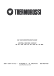
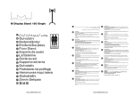
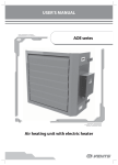
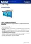
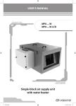
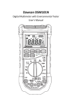
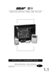
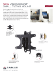
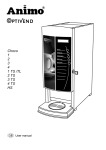
USER’S MANUAL
Air duct heater with integrated
temperature control unit
or a control unit
2
CONTENTS
Safety requirements
Introduction
Use
Delivery set
Designation key
Main technical parameters
Design and operating logic
Mounting and set-up
Connection to power mains
Heater control
Manufacturer's warranty
Maintenance
Storage and transportation rules
Acceptance certificate
Seller's information
Mounting certificate
Warranty Card
3
5
5
5
5
6
12
15
18
20
20
21
21
22
22
22
23
3
SAFETY REQUIREMENTS
•
•
•
•
•
•
Read the user’s manual carefully prior to the operation and installation of the air duct heater with an integrated temperature
control unit, hereinafter the heater.
Installation and operation of the heater shall be performed in accordance with the present user’s manual as well as the provisions
of all the applicable local and national construction, electrical and technical codes and standards.
The warnings contained in the present user’s manual must be considered most seriously since they contain vital personal safety
information.
Failure to follow the safety regulations and rules may result in an injury or heater damage.
Read the manual carefully and keep it as long as you use the heater.
While transferring the heater control the user’s manual must be turned over to the receiving operator.
Symbol legend used in the manual:
WARNING!
DO NOT!
HEATER MOUNTING SAFETY PRECAUTIONS
The heater must be disconnected from the
power supply prior to installation, servicing or
repair operations.
Do not operate the heater beyond the
temperature range stated in the user's
manual or in aggressive or explosive
environments.
Do not position any heating devices or other
equipment in close proximity to the heater
power cord.
Do not use damaged equipment or
conductors to connect the heater to power
mains.
While installing the heater follow the safety
regulations specific to the use of electric tools.
Unpack the heater with care.
Do not change the power cord length at your
own discretion. Do not bend the power cord.
Avoid damaging the power cord.
Use the heater only as intended by the
manufacturer.
4
HEATER OPERATING SAFETY PRECAUTIONS
Do not touch the controls with wet hands. Do
not perform the heater maintenance with wet
hands.
Do not wash the heater with water. Protect
the heater electric parts from water ingress.
ON
Disconnect the heater from power supply
prior to maintenance.
Do not block the air duct when the heater is on.
OFF
Do not let children operate the heater.
Do not damage the power cable while
operating the heater. Do not put any objects
on the power cable.
Keep combustible and inflammable substances
away of the heater.
In case of unusual sounds, smoke disconnect
the heater from power supply and contact
the service centre.
Do not cover the electric heater with any
materials. Do not place any appliances on top
of the heater.
Do not put any water containers (e.g. vases
etc.) on top of the heater.
5
INTRODUCTION
The present operation manual consisting of technical details, operating instructions and technical specification contains the
information specific to the installation and mounting of the following duct heater models:
•
NKU heater with a built-in temperature control unit for round ducts (from 0.6 kW to 2.4 kW);
•
NKU heater with a control unit for round ducts (from 3.0 kW to 9.0 kW);
•
NKU heater with a control unit for rectangular ducts (from 4.5 kW to 54 kW).
PURPOSE
The heater is intended to heat up the supply air entering the ventilation system. The built-in temperature control module or the
integral control unit ensure that air duct temperature is automatically maintained at the pre-set level.
The heater is designed for extended periods of continuous operation without disconnection from the power mains.
Being a component unit, the heater may not be commissioned for standalone operation.
Transported air must not contain any flammable or explosive mixtures, evaporation of chemicals, coarse dust, soot and oil particles,
sticky substances, fibrous materials, pathogens or any other harmful substances.
THE HEATER IS NOT INTENDED TO BE USED BY CHILDREN, PHYSICALLY OR MENTALLY DISABLED PERSONS, PERSONS
WITH SENSORY DISORDER, PERSONS WITH NO APPROPRIATE QUALIFICATION.
ANY OPERATIONS WITH THE HEATER MUST BE PERFORMED ONLY BY PROPERLY QUALIFIED PERSONNEL AFTER THE
APPROPRIATE SAFETY BRIEFING.
THE HEATER INSTALLATION SITES MUST PREVENT ACCESS BY UNATTENDED CHILDREN.
DELIVERY SET
Heater
1 item
User's manual
1 item
Packing box
1 item
DESIGNATION KEY
NKU for round ducts
NK Х-X-X U
Product type
NK — duct heater
Connected air duct diameter [mm]
Heater power [kW]
Phase
1 - single-phase
3 - three-phase
Integrated temperature control unit
NKU for rectangular ducts
NK XxХ- X-X U
Product type
NK - duct heater
Connected air duct width [mm]
400, 500, 600, 700, 800, 900, 1000
Connected air duct height [mm]
200, 250, 300, 350, 400, 500
Heater power [kW]
Phase
3 - three-phase
Integrated temperature control unit
6
MAIN TECHNICAL PARAMETERS
The heater is intended for operation in closed spaces under ambient air temperatures from +40 °C to +80 °C and relative humidity up
80%. The unit is capable of maintaining the duct temperature in the following range:
• From -10°C to +40°C (NKU units rated from 0.6 kW to 2.4 kW);
• From -0°C to +40°C (NKU units rated from 3.0 kW to 54 kW).
The heater must be grounded.
Hazardous parts access and water ingress protection standard is IP 40.
Allowable deviation from the rated voltage is ±10%.
The heater design is regularly improved, so some models may slightly differ from those ones described in this manual.
Technical data
NKU with integrated temperature
control unit for round air ducts
from 0.6 kW up to 2.4 kW
Min. air flow [m3/h]
Current consumption
[A]
Supply Voltage [V]
Number of electric
heating elements x
power [kW]
NK 100-0,6-1U
60
2,6
230
1 item х 0,6
NK 100-0,8-1U
80
3,5
230
1 item х 0,8
NK 100-1,2-1U
90
5,2
230
2 item х 0,6
NK 100-1,6-1U
120
7,0
230
2 item х 0,8
NK 100-1,8-1U
130
7,8
230
3 item х 0,6
NK 125-0,6-1U
60
2,6
230
1 item х 0,6
NK 125-0,8-1U
80
3,5
230
1 item х 0,8
NK 125-1,2-1U
90
5,2
230
2 item х 0,6
NK 125-1,6-1U
120
7,0
230
2 item х 0,8
NK 125-2,4-1U
150
7,8
230
3 item х 0,8
NK 150-1,2-1U
120
5,2
230
1 item х 1,2
NK 150-1,7-1U
130
7,4
230
1 item х 1,7
NK 150-2,0-1U
140
8,7
230
1 item х 2,0
NK 150-2,4-1U
150
10,4
230
2 item х 1,2
NK 160-1,2-1U
150
5,2
230
1 item х 1,2
NK 160-1,7-1U
160
7,4
230
1 item х 1,7
NK 160-2,0-1U
170
8,7
230
1 item х 2,0
NK 160-2,4-1U
180
10,4
230
2 item х 1,2
NK 200-1,2-1U
150
5,2
230
1 item х 1,2
NK 200-1,7-1U
160
7,4
230
1 item х 1,7
NK 200-2,0-1U
170
8,7
230
1 item х 2,0
NK 200-2,4-1U
180
10,4
230
2 item х 1,2
NK 250-1,2-1U
180
5,2
230
1 item х 1,2
NK 250-2,0-1U
200
8,7
230
1 item х 2,0
NK 250-2,4-1U
265
10,4
230
2 item х 1,2
NK 315-1,2-1U
180
5,2
230
1 item х 1,2
NK 315-2,0-1U
200
8,7
230
1 item х 2,0
NK 315-2,4-1U
265
10,4
230
2 item х 1,2
7
Technical data
NKU with integrated control unit
for round air ducts from 3.0 kW up
to 9.0 kW
Min. air flow [m3/h]
Current consumption
[A]
Supply Voltage [V]
Number of electric
heating elements x
power [kW]
NK 150-3,4-1U
220
14,7
230
2 item х 1,7
NK 150-3,6-3U
265
5,2
400
3 item х 1,2
NK 150-5,1-3U
320
7,4
400
3 item х 1,7
NK 150-6,0-3U
360
8,7
400
3 item х 2,0
NK 160-3,4-1U
250
14,8
230
2 item х 1,7
NK 160-3,6-3U
265
5,2
400
3 item х 1,2
NK 160-5,1-3U
375
7,4
400
3 item х 1,7
NK 160-6,0-3U
440
8,7
400
3 item х 2,0
NK 200-3,4-1U
250
14,8
230
2 item х 1,7
NK 200-3,6-3U
265
5,2
400
3 item х 1,2
NK 200-5,1-3U
375
7,4
400
3 item х 1,7
NK 200-6,0-3U
440
8,7
400
3 item х 2,0
NK 250-3,0-1U
375
13,0
230
1 item х 3,0
NK 250-3,6-3U
375
5,2
400
3 item х 1,2
NK 250-6,0-3U
440
8,7
400
3 item х 2,0
NK 250-9,0-3U
660
13,0
400
3 item х 3,0
NK 315-3,6-3U
375
5,2
400
3 item х 1,2
NK 315-6,0-3U
440
8,7
400
3 item х 2,0
NK 315-9,0-3U
660
13,0
400
3 item х 3,0
8
Technical data
NKU with integrated control unit
for rectangular air ducts from
4.5 kW up to 54 kW
Min. air flow
[m3/h]
Current consumption [A]
Supply Voltage
[V]
Power, kW
Number of
electric heating
elements x
power [kW]
NK 400x200-4,5-3U
330
6,5
400
4,5
3 item х1,5
NK 400x200-6,0-3U
440
8,7
400
6,0
3 item х2,0
NK 400x200-7,5-3U
550
10,9
400
7,5
3 item х2,5
NK 400x200-9,0-3U
660
13,0
400
9,0
3 item х3,0
NK 400x200-10,5-3U
770
15,2
400
10,5
3 item х3,5
NK 400x200-12,0-3U
880
17,4
400
12,0
3 item х4,0
NK 400x200-15,0-3U
1100
21,7
400
15,0
3 item х5,0
NK 500x250-6,0-3U
440
8,7
400
6,0
3 item х2,0
NK 500x250-7,5-3U
550
10,9
400
7,5
3 item х2,5
NK 500x250-9,0-3U
660
13,0
400
9,0
3 item х3,0
NK 500x250-10,5-3U
770
15,2
400
10,5
3 item х3,5
NK 500x250-12,0-3U
880
17,4
400
12,0
3 item х4,0
NK 500x250-15,0-3U
1100
21,7
400
15,0
3 item х5,0
NK 500x250-18,0-3U
1320
26,0
400
18,0
3 item х6,0
NK 500x250-21,0-3U
1540
30,0
400
21,0
3 item х7,0
NK 500x300-6,0-3U
440
8,7
400
6,0
3 item х2,5
NK 500x300-7,5-3U
550
10,9
400
7,5
3 item х3,0
NK 500x300-9,0-3U
660
13,0
400
9,0
3 item х3,5
NK 500x300-10,5-3U
770
15,2
400
10,5
3 item х4,0
NK 500x300-12,0-3U
880
17,4
400
12,0
3 item х5,0
NK 500x300-15,0-3U
1100
21,7
400
15,0
3 item х6,0
NK 500x300-18,0-3U
1320
26,0
400
18,0
3 item х7,0
NK 500x300-21,0-3U
1540
30,0
400
21,0
3 item х2,5
NK 600x300-9,0-3U
660
13,0
400
9,0
3 item х3,0
NK 600x300-12,0-3U
880
17,4
400
12,0
3 item х4,0
NK 600x300-15,0-3U
1100
21,7
400
15,0
3 item х5,0
NK 600x300-18,0-3U
1320
26,0
400
18,0
3 item х6,0
NK 600x300-21,0-3U
1540
30,0
400
21,0
3 item х7,0
NK 600x300-24,0-3U
1760
34,7
400
24,0
3 item х8,0
NK 600x350-9,0-3U
660
13,0
400
9,0
3 item х3,0
NK 600x350-12,0-3U
880
17,4
400
12,0
3 item х4,0
NK 600x350-15,0-3U
1100
21,7
400
15,0
3 item х5,0
NK 600x350-18,0-3U
1320
26,0
400
18,0
3 item х6,0
NK 600x350-21,0-3U
1540
30,0
400
21,0
3 item х7,0
NK 600x350-24,0-3U
1760
34,7
400
24,0
3 item х8,0
NK 700x400-18,0-3U
1320
26,0
400
18,0
6 item х3,0
NK 700x400-27,0-3U
1980
39,0
400
27,0
9 item х3,0
NK 700x400-36,0-3U
2640
52,0
400
36,0
12 item х3,0
NK 800x500-27,0-3U
1980
39,0
400
27,0
9 item х3,0
NK 800x500-36,0-3U
2640
52,0
400
36,0
12 item х3,0
NK 800x500-54,0-3U
3960
78,0
400
54,0
18 item х3,0
NK 900x500-45,0-3U
3300
65,0
400
45,0
15 item х3,0
NK 900x500-54,0-3U
3960
78,0
400
54,0
18 item х3,0
NK 1000x500-45,0-3U
3300
65,0
400
45,0
15 item х3,0
NK 1000x500-54,0-3U
3960
78,0
400
54,0
18 item х3,0
9
NKU OVERALL DIMENSTIONS FOR ROUND DUCTS FROM 0.6 kW UP TO 2.4 kW
L1
H
ØD
B
L
NKU with integrated temperature
control unit for round air ducts
from 0.6 kW up to 2.4 kW
D [mm]
B [mm]
H [mm]
L [mm]
L1 [mm]
Weight [kg]
NK 100-0,6-1U
99
94
204
306
227
1,5
NK 100-0,8-1U
99
94
204
306
227
1,5
NK 100-1,2-1U
99
120
204
370
290
1,6
NK 100-1,6-1U
99
120
204
370
290
1,6
NK 100-1,8-1U
99
120
204
454
374
1,8
NK 125-0,6-1U
124
103
230
306
227
1,6
NK 125-0,8-1U
124
103
230
306
227
1,6
NK 125-1,2-1U
124
126
230
370
290
1,8
NK 125-1,6-1U
124
126
230
370
290
1,8
NK 125-2,4-1U
124
126
230
454
374
2
NK 150-1,2-1U
149
144
255
306
226
2,1
NK 150-1,7-1U
149
144
255
306
226
2,1
NK 150-2,0-1U
149
144
255
306
226
2,1
NK 150-2,4-1U
149
144
255
370
290
2,6
NK 160-1,2-1U
159
154
267
306
226
2,2
NK 160-1,7-1U
159
154
267
306
226
2,2
NK 160-2,0-1U
159
154
267
306
226
2,2
NK 160-2,4-1U
159
154
267
370
290
2,8
NK 200-1,2-1U
199
174
302
306
228
2,6
NK 200-1,7-1U
199
174
302
306
228
2,6
NK 200-2,0-1U
199
174
302
306
228
2,6
NK 200-2,4-1U
199
174
302
376
298
3,2
NK 250-1,2-1U
249
174
356
306
228
3,3
NK 250-2,0-1U
249
174
356
306
228
3,3
NK 250-2,4-1U
249
174
356
376
298
3,9
NK 315-1,2-1U
313
174
425
306
228
4,1
NK 315-2,0-1U
313
174
425
306
228
4,1
NK 315-2,4-1U
313
174
425
376
298
5
10
NKU OVERALL DIMENSTIONS FOR ROUND DUCTS FROM 3.0 kW UP TO 9.0 kW
L1
B
H
L
ØD
NKU with integrated control unit
for round air ducts from 3.0 kW up
to 9.0 kW
D [mm]
B [mm]
H [mm]
L [mm]
L1 [mm]
Weight [kg]
NK 150-3,4-1U
149
187
340
370
298
4,3
NK 150-3,6-3U
149
187
340
370
298
4,9
NK 150-5,1-3U
149
187
340
370
298
4,9
NK 150-6,0-3U
149
187
340
370
298
4,9
NK 160-3,4-1U
159
187
350
370
298
4,6
NK 160-3,6-3U
159
187
350
370
298
5,2
NK 160-5,1-3U
159
187
350
370
298
5,2
NK 160-6,0-3U
159
187
350
370
298
5,2
NK 200-3,4-1U
199
237
389
376
298
5,2
NK 200-3,6-3U
199
237
389
376
298
5,9
NK 200-5,1-3U
199
237
389
376
298
5,9
NK 200-6,0-3U
199
237
389
376
298
5,9
NK 250-3,0-1U
249
237
446
376
298
5,1
NK 250-3,6-3U
249
237
446
376
298
6,6
NK 250-6,0-3U
249
237
446
376
298
6,6
NK 250-9,0-3U
249
237
446
376
298
6,6
NK 315-3,6-3U
313
237
514
376
298
5,6
NK 315-6,0-3U
313
237
514
376
298
7,4
NK 315-9,0-3U
313
237
514
376
298
7,4
11
OVERALL DIMENSIONS OF NKU HEATERS FOR RECTANGULAR DUCTS FROM 4.5 kW TO 54 kW
H2
H1
L
H
Ø9
B
B1
B3
NKU Heater with a Control Unit
for Rectangular Ducts from 4.5
kW to 54 kW
NK 400x200-4,5-3U
B [mm]
B1 [mm]
B3 [mm]
H [mm]
H1 [mm]
Н2 [mm]
L [mm]
Weight
[kg]
400
420
611
200
220
240
228
18,24
NK 400x200-6,0-3U
400
420
611
200
220
240
228
18,24
NK 400x200-7,5-3U
400
420
611
200
220
240
228
18,24
NK 400x200-9,0-3U
400
420
665
200
220
240
228
18,52
NK 400x200-10,5-3U
400
420
665
200
220
240
228
18,52
NK 400x200-12,0-3U
400
420
665
200
220
240
228
18,52
NK 400x200-15,0-3U
400
420
665
200
220
240
228
18,52
NK 500x250-6,0-3U
500
520
702
250
270
290
228
22,4
NK 500x250-7,5-3U
500
520
702
250
270
290
228
22,4
NK 500x250-9,0-3U
500
520
702
250
270
290
228
23,0
NK 500x250-10,5-3U
500
520
702
250
270
290
228
23,0
NK 500x250-12,0-3U
500
520
702
250
270
290
228
23,0
NK 500x250-15,0-3U
500
520
702
250
270
290
228
23,1
NK 500x250-18,0-3U
500
520
702
250
270
290
228
23,1
NK 500x250-21,0-3U
500
520
702
250
270
290
228
23,1
NK 500x300-6,0-3U
500
520
702
300
320
340
228
22,9
NK 500x300-7,5-3U
500
520
702
300
320
340
228
22,9
NK 500x300-9,0-3U
500
520
702
300
320
340
228
23,5
NK 500x300-10,5-3U
500
520
702
300
320
340
228
23,5
NK 500x300-12,0-3U
500
520
702
300
320
340
228
23,5
NK 500x300-15,0-3U
500
520
702
300
320
340
228
24,0
NK 500x300-18,0-3U
500
520
702
300
320
340
228
24,0
NK 500x300-21,0-3U
500
520
702
300
320
340
228
24,0
NK 600x300-9,0-3U
600
620
802
300
320
340
228
27,0
NK 600x300-12,0-3U
600
620
802
300
320
340
228
27,0
NK 600x300-15,0-3U
600
620
802
300
320
340
228
27,0
NK 600x300-18,0-3U
600
620
802
300
320
340
228
27,5
NK 600x300-21,0-3U
600
620
802
300
320
340
228
27,5
NK 600x300-24,0-3U
600
620
802
300
320
340
228
27,5
12
NKU Heater with a Control Unit
for Rectangular Ducts from 4.5
kW to 54 kW
B [mm]
B1 [mm]
B3 [mm]
H [mm]
H1 [mm]
Н2 [mm]
L [mm]
Weight
[kg]
NK 600x350-9,0-3U
600
620
802
350
370
390
228
28,2
NK 600x350-12,0-3U
600
620
802
350
370
390
228
28,2
NK 600x350-15,0-3U
600
620
802
350
370
390
228
28,5
NK 600x350-18,0-3U
600
620
802
350
370
390
228
28,5
NK 600x350-21,0-3U
600
620
802
350
370
390
228
28,5
NK 600x350-24,0-3U
600
620
802
350
370
390
228
28,5
NK 700x400-18,0-3U
700
720
924
400
420
440
410
16,8
NK 700x400-27,0-3U
700
720
924
400
420
440
530
21,0
NK 700x400-36,0-3U
700
720
924
400
420
440
750
28,0
NK 800x500-27,0-3U
800
820
1024
500
520
540
410
20,6
NK 800x500-36,0-3U
800
820
1024
500
520
540
530
25,9
NK 800x500-54,0-3U
800
820
1024
500
520
540
750
36,1
NK 900x500-45,0-3U
900
920
1130
500
520
540
750
33,4
NK 900x500-54,0-3U
900
920
1130
500
520
540
750
35,0
NK 1000x500-45,0-3U
1000
1020
1230
500
520
540
750
35,5
NK 1000x500-54,0-3U
1000
1020
1230
500
520
540
750
41,2
DESIGN AND OPERATING LOGIC
NKU HEATER WITH A BUILT-IN TEMPERATURE CONTROL UNIT FOR ROUND DUCTS
The heater casing has a rigidly mounted junction box protected with a removable lid.
The front panel of the junction box has the electronic thermostat control knob with a temperature scale. The heater is equipped with
a temperature sensor built into the air duct. The sensing element is encapsulated in an aluminium tube protecting it against mechanical
damage. The rear panel of the junction box has a sealed lead-in for the heater feed lines and the grounding conductor. The heater casing
encloses electic heating elments.
The heater casing, junction box and protective lid are made of galvanized steel.
The junction box contains the following components:
• Fasteners for the heating elements;
• Electrical components for the power mains connection;
• The terminal block for connecting the external feed lines of the heater;
• Grounding screw clamp;
• Manual reset thermoswitch;
• Electronic thermostat controller circuit board.
In the NK100, 125 - 0.6 .. 0.8 -1U models the TRIAC is installed on a heat sink inside the junction box. All other models feature external
heat sinks to dissipate extra heat.
The heater is also equipped with a manual reset thermoswitch rated to trip at +60 °C. The thermoswitch actuation may be caused by
an abnormal temperature increase in the event of the thermostat electronic unit failure.
The electrical connections diagram is given on the inside of the junction box lid.
Junction Box Lid
Heat Sink
Sealed Lead-In
Temperature Sensor
Casing
Tubular Heating
Element
Temperature Selection Knob
13
NKU HEATER WITH A CONTROL UNIT FOR ROUND AND RECTANGULAR DUCTS
The duct heater is equipped with a three-phase TRIAC power controller to regulate the output of the tubular electric heating elements.
The units benefit from proportional-integral control used for adjusting the supply air temperature with automatic control function
adaptation.
The control unit can use the temperature sensor feedback to maintain the pre-set duct temperature or the heating output
proportionally to the 0-10 V external control signal value in the range from 0 to 100%.
While switching the duct temperature sensor mode select one of the temperature sensors below:
- Duct temperature sensor with a sealed end KDT2-M1 (100...400 mm);
- Duct sensor with a mounting flange encased in a rolled tube KDT2-M (100...400 mm);
- Duct sensor with a mounting flange encased in a rolled tube equipped with a terminal box KDT2-M (100...400 mm).
The temperature is controlled by means of connecting and disconnecting the full load. The TRIAC power controller of the NKU heaters
effects proportional time control by changing the relation between the load on-time and off-time depending on the pre-programmed
heating requirements. For example, if the full load is intermittently on and off in 5 second periods the heater runs at 50% of its maximum
power output. The cycle time (i.e. the total of the load on-time and off-time) is programmed at the factory in the range from 1 to 6
seconds by using the appropriately rated resistance 3 (see Fig. 14). The load is commutated by means of a TRIAC controller.
The NKU has two built-in thermal contacts for overheating protection: the automatic reset TK50 with intervention temperature of +50 °C
and the manual reset TK90 with intervention temperature of +90 °C. The thermal contacts are connected to the control unit terminals.
The air temperature is set by means of the integral pot resistor or an external control device generating a 0-10 V control input signal to
increase the duct temperature proportionally in the range from 0 to +40 °C.
The NKU heaters with integral control units for round ducts consist of a casing with a rigidly mounted junction box which has a removable
top lid.
Control Unit
Lid
Heat Sink
Indicator Panel
Sealed Lead-In
Temperature Control
Knob
ON/OFF Button
Casing
Tubular Heating
Element
The NKU heaters with integral control units for rectangular ducts consist of a casing with a rigidly mounted junction box. The junction
box has a removable front panel featuring the temperature control knob, the ON/OFF button and the indicator panel.
Heat Sink
ON/OFF Button
Indicator Panel
Temperature Control Knob
Casing
Tubular
Heating Element
Sealed Lead-In
14
Functional Switches and Indicators
There are three lights on the indicator panel:
• Power – AC Mains (Green Light);
• Status lights – Operation (Yellow);
• Alarm/Booster Heating (Red).
Alarm/ Booster
Operation Heating
AC Mains
Current State and Malfunction Indication
AC Mains
Green Light
Operation
Yellow
Alarm/Booster
Heating
Red Light
Event
OFF
OFF
OFF
AC Mains Disconnected
ON
ON
BLINKS IN 5 s INTERVALS
Temperature Boosting T set >T flow
ON
ON
ON
Switching to Mode T set = T flow
ON
OFF
ON
Overheating T set < T flow
ON
ON
BLINKS IN 1 s INTERVALS
Duct Pressure Switch Signal Lost
ON
BLINKS IN 1 s
INTERVALS
ON
TK50 thermal contact actuation
ON
Alternate Blinking
Heating Power Output Maintenance Irrespective of Sensor
Feedback
ON
Simultaneous Blinking
Alarm
Controller Circuit Board Functional Outputs:
1 - Internal or External 0-10 V Control Input Selection;
2 - Control Mode Selection;
3 - Cycle Length Adjustment Resistor (factory-set);
4 - Indication of TRIAC Operation and Heating Cascade Activation;
5 - Heating Cascade 1 Indicator;
6 - Second Heating Cascade Indicator ;
7 - Heating Cascade 3 Indicator;
8 - Terminal Block for Temperature Sensor Connection;
9 - Terminal Block for External 0-10 V Control Input;
10 - Terminal Block for Protection and Enabling Contacts;
11 - Control Circuit Board Fuse.
To facilitate connection by the user Outputs 8, 9 and 10 are factory-commutated on the X2 terminal block (see Page 20 «Heater Control»).
X5
IN 3
X6
IN 1
15 16 17
IN 2
12 13 14
10
GND
Tset
J1
+10V
GND
PT+
A1
1
9
PTin
GND
8
Jumper 1
18 19 20 21
External Signal Source (0-10) V
X4
Internal Pot Resistor (0-10) V
J2
Jumper 2
K1
SCR
Temperature Sensor Feedback
Mode Using Three Cascades
7 6 5 4
K2
Temperature Sensor Feedback
Mode Using Cascade 1
K1
Heating Power Output
Maintenance Mode Using Cascade 1
X3
X7
8
7
6
5
4
DO1
DO1
DO2
DO2
3
L
9
CQ
11 10
Q1
F1
100mA
11
2
1
N
X8
PE
X2
Q2
K3
3
Q3
R85
K2
K3
2
Heating Power Output
Maintenance Mode Using Three
Cascades
15
MOUNTING AND SETUP
READ THIS USER’S MANUAL CAREFULLY PRIOR TO THE HEATER INSTALLATION.
AFTER TRANSPORTATION OR STORAGE UNDER BELOW ZERO TEMPERATURES
KEEP THE UNIT IN THE SPECIFIED OPERATION CONDITIONS FOR AT LEAST 4
HOURS BEFORE POWERING UP.
Prior to the heater installation check the heater for the integrity and reliability of the heating element fixation.
The working position of the heater must ensure unimpeded access to the junction box (control unit) and the RESET thermoswitch
manual reset button mounted inside the control unit.
The heater must be securely fastened in place. The mounting location must enable quick access to the heater and provide ample
space for technical maintenance operations.
The heater must be installed into the ventilation system so that the arrow on the heater casing matches the air flow direction.
The minimum clearance between the heater and other ventilation system components should double the connection size.
No inflammable, explosive or fire-hazardous materials are allowed within 150 mm of the heater casing and within 500 mm of the
heater air inlet and outlet. Air ducts and fans must be equipped with a grille or similar protective device preventing free access to the
tubulr heating elements.
Pre-commissioning precautions:
The unit must be safely earthed in compliance with the «Electrical Installations Regulations» (i.e. the clamp must be connected to the
protective ground wire);
• The minimum air flow through the heater must comply with the value stated in the technical specification (see pages 6, 7, 8).
The fan must be installed in the air duct upstream of the heater along the air flow direction to eliminate the possibility of extra heat
load on the electric motor. Wherever possible a supply filter should be installed upstream of the heater to reduce contamination.
To ensure proper and safe operation the heater should be equipped with an automatic control system capable of comprehensive
control and protection - in particular:
• Monitoring the filter condition using the pressure differential sensor feedback;
• Powering off the heater in the event of the supply fan shutdown or air flow velocity drop as well as upon actuation of the built-in
overheating protection thermostat;
• Ventilation system shutdown after a 30-second blowing cycle required to cool down the electric heating elements.
The supply voltage must be fed via an automatic circuit breaker with a minimum gap of 3 mm between the open contacts on all poles.
The circuit breaker must be integrated into the stationary wiring in accordance with the applicable electrical wiring regulations.
To access the terminal block remove the junction box (control unit) lid.
•
NKU Terminal Block Access
16
Connecting Round Air Ducts to the Heater
The heater is designed for internal installation into air ducts in the horizontal or vertical position. Horizontal Position Installation. In
a horizontal position the junction box must face upwards. The horizontal deviation may be up to 90°. The heater junction box may not
face downwards.
Connecting Rectangular Air Ducts to the Heater
17
CONNECTION TO POWER MAINS
DISCONNECT THE HEATER FROM THE POWER SUPPLY PRIOR TO ANY WORK ON THE UNIT. THE POWER MAINS
CONNECTION SHALL ONLY BE PERFORMED BY A PROFESSIONAL ELECTRICIAN. THE NOMINAL ELECTRICAL
PARAMETERS OF THE HEATER ARE GIVEN ON THE MANUFACTURER’S LABEL. ANY TAMPERING WITH THE INTERNAL
CONNECTIONS IS PROHIBITED AND WILL VOID THE WARRANTY.
The heater is powered with 230 V / 50 Hz single-phase alternating current or 400 V / 50 Hz three-phase current depending on the particular
NKU model. The heater connection must be made on the terminal block mounted on a plank inside the junction box or the control unit in
accordance with the electrical connections diagram and terminal designations as shown on the respective schematic.
Route the cables into the unit through sealed lead-ins in the casing sidewall as per the electric hazard class specifications. The external leadin (230 V / 50 Hz or 400 V / 50Hz) must be equipped with an automatic circuit breaker built into the stationary wiring to interrupt all the network
phases. The location of the QF external switch must ensure free access for quick shutdown of the heater. The protection trip current must be
consistent with the current consumption of the unit. The recommended nominal trip current of the circuit breaker, the cross-section and the
number of cores are given in the respective tables.
The heater connections (cables and wires) must be durable, insulated and heat-resistant. The given wire sections are for reference only. The
conductor section selection must account for the maximum permissible wire heating which depends on the wire type, its insulation, length and
installation method (i.e. overhead, in pipes or inside walls).
CONNECTION OF NKU WITH INTEGRATED TEMPERATURE CONTROL UNIT FOR ROUND AIR DUCTS
Automatic Circuit Breaker Trip Current Selection for NKU Heaters with an Integrated Temperature Control Unit for Round
Ducts from 0.6 kW to 2.4 kW
Nku heater with a built-in temperature control
unit for round ducts from 0.6 Kw to 2.4 Kw
Supply Voltage [V]
Circuit Breaker Trip
Current [A]
Number and CrossSection of Cores [mm2]
NK 100-0,6-1U
230
3,15
3х0,75
NK 100-0,8-1U
230
4,0
3х0,75
NK 100-1,2-1U
230
6,3
3х2,5
NK 100-1,6-1U
230
8,0
3х2,5
NK 100-1,8-1U
230
10,0
3х2,5
NK 125-0,6-1U
230
3,15
3х0,75
NK 125-0,8-1U
230
4,0
3х0,75
NK 125-1,2-1U
230
6,3
3х2,5
NK 125-1,6-1U
230
8,0
3х2,5
NK 125-2,4-1U
230
10,0
3х2,5
NK 150-1,2-1U
230
6,3
3х2,5
NK 150-1,7-1U
230
8,0
3х2,5
NK 150-2,0-1U
230
10,0
3х2,5
NK 150-2,4-1U
230
12,5
3х2,5
NK 160-1,2-1U
230
6,3
3х2,5
NK 160-1,7-1U
230
8,0
3х2,5
NK 160-2,0-1U
230
10,0
3х2,5
NK 160-2,4-1U
230
12,5
3х2,5
NK 200-1,2-1U
230
6,3
3х2,5
NK 200-1,7-1U
230
8,0
3х2,5
NK 200-2,0-1U
230
10,0
3х2,5
NK 200-2,4-1U
230
12,5
3х2,5
NK 250-1,2-1U
230
6,3
3х2,5
NK 250-2,0-1U
230
10,0
3х2,5
NK 250-2,4-1U
230
12,5
3х2,5
NK 315-1,2-1U
230
6,3
3х2,5
NK 315-2,0-1U
230
10,0
3х2,5
NK 315-2,4-1U
230
12,5
3х2,5
18
Wiring Diagrams for NKU Heaters from 0.6 kW to 2.4 kW
~230 V/50Hz
L N
PE
~230 V/50Hz
L N
PE
L
L
N PE
6
5
4
3
2
4
3
X1
1
QF
NK 100-0,6-1U
NK 100-0,8-1U
NK 125-0,6-1U
NK 125-0,8-1U
2
X1
1
QF
NK 100-1,2-1U
NK 100-1,6-1U
NK 100-1,8-1U
NK 125-1,2-1U
NK 125-1,6-1U
NK 125-2,4-1U
NK 150-1,2-1U
NK 150-1,7-1U
NK 150-2,0-1U
NK 150-2,4-1U
NK 160-1,2-1U
NK 160-1,7-1U
NK 160-2,0-1U
NK 160-2,4-1U
NK 200-1,2-1U
NK 200-1,7-1U
NK 200-2,0-1U
NK 200-2,4-1U
NK 250-1,2-1U
NK 250-2,0-1U
NK 250-2,4-1U
NK 315-1,2-1U
NK 315-2,0-1U
NK 315-2,4-1U
N PE
CONNECTION OF NKU WITH CONTROL UNIT FOR ROUND AND RECTANGULAR DUCTS
Automatic Circuit Breaker Trip Current Selection for NKU Heaters with a Control Unit for Round Ducts from 3.0 kW to 9.0 kW
NKU Heaters with a Control Unit
for Round Ducts
from 3.0 kW to 9.0 kW
Supply Voltage [V]
Circuit Breaker Trip
Current [A]
Number and CrossSection of Cores [mm2]
NK 150-3,4-1U
230
20
3х2,5
NK 160-3,4-1U
230
20
3х2,5
NK 200-3,4-1U
230
20
3х2,5
NK 250-3,0-1U
230
20
3х2,5
NK 150-3,6-3U
400
8
5х2,5
NK 160-3,6-3U
400
8
5х2,5
NK 200-3,6-3U
400
8
5х2,5
NK 250-3,6-3U
400
8
5х2,5
NK 315-3,6-3U
400
8
5х2,5
NK 150-5,1-3U
400
10
5х2,5
NK 160-5,1-3U
400
10
5х2,5
NK 200-5,1-3U
400
10
5х2,5
NK 250-6,0-3U
400
10
5х2,5
NK 315-6,0-3U
400
10
5х2,5
NK 250-9,0-3U
400
16
5х2,5
NK 315-9,0-3U
400
16
5х2,5
Wiring Diagram for NKU Heaters with a Control Unit
for Round Ducts from 3.0 kW to 9.0 kW
Wiring Diagram for NKU Heaters with a Control Unit for
Round Ducts (from 3.0 kW to 9.0 kW) and for the entire
model range of Rectangular Ducts (from 4.5 kW to 54 kW)
~400 V/50Hz
L1 L2 L3 N
~230 V/50Hz
L N
PE
N PE
5
4
3
X1
2
3
2
1
L
NK 150-3,4-1U
NK 160-3,4-1U
NK 200-3,4-1U
NK 250-3,0-1U
1
QF
QF
X1
PE
L1 L2 L3 N PE
NK 150-3,6-3U
NK 150-5,1-3U
NK 150-6,0-3U
NK 160-3,6-3U
NK 160-5,1-3U
NK 160-6,0-3U
NK 200-3,6-3U
NK 200-5,1-3U
NK 200-6,0-3U
NK 250-3,6-3U
NK 250-6,0-3U
NK 250-9,0-3U
NK 315-3,6-3U
NK 315-6,0-3U
NK 315-9,0-3U
19
Automatic Circuit Breaker Trip Current Selection for NKU Heaters with a Control Unit for Rectangular Ducts from 4.5 kW to
54 kW
NKU Heaters with a Control Unit
for Rectangular Ducts
from 4.5 kW to 54 kW
Supply Voltage [V]
Circuit Breaker Trip
Current [A]
Number and Cross-Section of Cores [mm2]
NK 400x200-4,5-3U
400
10
5х2,5
NK 400x200-6,0-3U
400
50
5х2,5
NK 400x200-7,5-3U
400
16
5х2,5
NK 400x200-9,0-3U
400
16
5х2,5
NK 400x200-10,5-3U
400
20
5х2,5
NK 400x200-12,0-3U
400
20
5х2,5
NK 400x200-15,0-3U
400
25
5х2,5
NK 500x250-6,0-3U
400
10
5х2,5
NK 500x250-7,5-3U
400
16
5х2,5
NK 500x250-9,0-3U
400
16
5х2,5
NK 500x250-10,5-3U
400
20
5х2,5
NK 500x250-12,0-3U
400
20
5х2,5
NK 500x250-15,0-3U
400
25
5х2,5
NK 500x250-18,0-3U
400
31,5
5х4
NK 500x250-21,0-3U
400
40,0
5х4
NK 500x300-6,0-3U
400
10
5х2,5
NK 500x300-7,5-3U
400
16
5х2,5
NK 500x300-9,0-3U
400
16
5х2,5
NK 500x300-10,5-3U
400
20
5х2,5
NK 500x300-12,0-3U
400
20
5х2,5
NK 500x300-15,0-3U
400
25
5х2,5
NK 500x300-18,0-3U
400
31,5
5х4
NK 500x300-21,0-3U
400
40
5х4
NK 600x300-9,0-3U
400
16
5х2,5
NK 600x300-12,0-3U
400
20
5х2,5
NK 600x300-15,0-3U
400
25
5х2,5
NK 600x300-18,0-3U
400
31,5
5х4
NK 600x300-21,0-3U
400
40
5х4
NK 600x300-24,0-3U
400
40
5х4
NK 600x350-9,0-3U
400
16
5х2,5
NK 600x350-12,0-3U
400
20
5х2,5
NK 600x350-15,0-3U
400
25
5х2,5
NK 600x350-18,0-3U
400
30
5х4
NK 600x350-21,0-3U
400
40
5х4
NK 600x350-24,0-3U
400
40
5х4
NK 700x400-18,0-3U
400
31,5
5х4
NK 700x400-27,0-3U
400
50
5х6
NK 700x400-36,0-3U
400
63
5х10
NK 800x500-27,0-3U
400
50
5х6
NK 800x500-36,0-3U
400
63
5х10
NK 800x500-54,0-3U
400
100
5х16
NK 900x500-45,0-3U
400
80
5х10
NK 900x500-54,0-3U
400
100
5х16
NK 1000x500-45,0-3U
400
80
5х10
NK 1000x500-54,0-3U
400
100
5х16
20
HEATER CONTROL
NKU HEATER WITH A BUILT-IN TEMPERATURE CONTROL UNIT FOR ROUND DUCTS
Use the temperature control knob to set the desired temperature in the air duct (thermostat operation threshold).
The temperature can be set in the range from -10°C to +40°C.
The heater switches on automatically upon the air temperature dropping below the pre-set thermostat operation threshold.
When the air warms up to the pre-set level the heater switches off automatically.
NKU HEATERS WITH CONTROL UNIT FOR ROUND AND RECTANGULAR DUCTS
Complete the electrical connections according to the respective diagram, see Page 18.
To use the temperature sensor feedback connect the sensor to the X2 terminal block:
TE1 [Gnd, PTin, PT+].
PT+ - Sensor Power - «Brown»;
Gnd - Analogue Ground Contact - «Shield»;
PTin - Sensor Signal Input - «White».
Jumper 1 (see Page 14) toggles the heater control method (the 0-10 V control signal or the feedback from the built-in temperature
controller pot resistor).
To use the feedback from an external control device connect it to the X2 terminal block.
Control [GND, 0-10 V].
Gnd - Analogue Ground Contact
0-10V - External Signal Input.
Protective Contact Circuit Connection.
The «Start» signal (the activation signal source device) must be connected to the X2 terminal: Enable [nc and s ]
The flow sensing element (the supply filter pressure switch) must be connected to the X2 terminal: PD1 [nc and s];
TK50 (the heater overheating protection thermoswitch set to actuate at +50 °C) is connected to the A1 controller terminal at the
factory:
- [Gnd and In2] (see Page 14);
TK90 (the heater overheating protection thermoswitch set to actuate at +90 °C) is connected to the A1 controller terminal at the
factory:
- CQ (see Page 14) and to the circuit of the master switch (see Page 14).
Supply the power voltage to the unit and activate the heater by pressing the ON/OFF button. Then use the controller knob connected
to the pot resistor to set the desired temperature in the range from 0°C to +40°C.
The NKU heaters equipped with a control unit have one or several power relays depending on the number of the controlled
cascades in use. The relays are connected to the controller circuit board via the TK 90 protective thermal contact at the factory.
EXTERNAL CONNECTIONS DIAGRAM
Thermoresistor
tE
Air Flow
Sensor
0-10V
Controller
Control
PD1
c
9
8
7
6
5
4
Brown
GND PTin PT+ GND 0-10V nc
TE1
“Start”
Signal
E+
3
White
2
X2
1
Shield
Gnd Out
External
Temperature
Signal
Source
nc c
Enable
MAINTENANCE
THE HEATER TECHNICAL MAINTENANCE MUST BE PERFORMED BY ADEQUATELY QUALIFIED AND TRAINED PERSONNEL
UPON HEATER DISCONNECTION FROM THE POWER MAINS.
Heater maintenance includes:
• inspection of screw, rivet and welded connections;
• inspection of screw ground clamp tightening and electric connections;
• inspection of wire terminal connections;
• cleaning of the heating elements of dust and dirt. Cleaning with solvents or flammable substances is not allowed.
21
STORAGE AND TRANSPORTATION RULES
Store the heater in the manufacturer’s original packing box in a dry ventilated premise at the temperatures from +5 °C up to +40 °C.
Storage environment must not contain aggressive vapours and chemical mixtures provoking corrosion, insulation and sealing
deformation.
Use hoist machinery for handling and storage operations to prevent the heater damage.
Fulfil the handling requirements applicable for the applicable freight type.
Transportation with any vehicle type is allowed provided that the heater is protected against mechanical and weather damage.
Avoid any mechanical shocks and strokes during handling operations.
MANUFACTURER’S WARRANTY
The manufacturer hereby warrants normal operation of the heater over the period of 24 months from the retail sale date provided the
user’s observance of the transportation, storage, installation and operation regulations.
Should any malfunctions occur during the heater operation through the manufacturer’s fault during the warranty period the user is
entitled to elimination of faults by means of warranty repair performed by the manufacturer.
The warranty repair includes work specific to elimination of faults in the heater operation to ensure its intended use by the user within
the warranty period. The faults are eliminated by means of replacement or repair of the complete heater or the faulty part thereof.
The warranty repair does not include:
•
Routine maintenance;
•
Heater installation / dismantling;
•
Heater setup.
To benefit from warranty repair the user must provide the heater, the user’s manual with stamped sale date and the payment
document certifying the purchase.
The heater model must comply with the one stated in the user’s manual.
Contact your Seller for warranty service.
The manufacturer’s warranty does not apply to the following cases:
•
User’s failure to provide the heater with the entire delivery package as stated in the user’s manual or with missing component parts
previously dismounted by the user;
•
Mismatch of the heater model and make with the respective details stated on the heater packing and in the user’s manual;
•
User’s failure to ensure timely technical maintenance of the heater;
•
External damage to the casing (excluding external modifications of the heater as required for its installation) and the internal
components of the heater;
•
Alteration of the heater design or engineering changes of the heater;
•
Replacement and use of the heater assemblies, parts and components not approved by the manufacturer;
•
heater misuse;
•
User’s violation of the heater installation regulations;
•
User’s violation of the heater control regulations;
•
heater connection to the power pains with a voltage different from the one stated in the user’s manual;
•
heater breakdown due to voltage surges in the power mains;
•
User’s discretionary repair of the heater;
•
heater repair performed by any non-authorised by the manufacturer persons;
•
Expiry of the heater warranty period;
•
User’s violation of the established regulations specific to the heater transportation;
•
User’s violation of the heater storage regulations;
•
Wrongful acts against the heater committed by third persons;
•
heater breakdown due to circumstances of insuperable force (fire, flood, earthquake, war, hostilities of any kind, or blockade);
•
Missing seals if provided by the user’s manual;
•
Failure to provide the user’s manual with the sale date stamp;
•
Missing payment document certifying the heater purchase.
FOLLOWING THE REGULATIONS STIPULATED HEREIN WILL ENSURE A LONG AND
TROUBLE-FREE OPERATION OF THE heater.
USERS’ CLAIMS SHALL BE SUBJECT TO REVIEW ONLY UPON PRESENTATION OF
THE heater, THE PAYMENT DOCUMENT AND THE USER’S MANUAL WITH THE SALE
DATE STAMP.
22
ACCEPTANCE CERTIFICATE
Product Type
The air duct heater with integrated temperature control unit or control unit
Model
NK ________ U
Serial number
Manufacturing date
Is recognized as serviceable.
The product complies with the requirements according to the EU norms and directives, to the relevant EU-Low Voltage Equipment
Directives, EU-Directives on Electromagnetic Compatibility. We hereby declare that the following product complies with the essential
protection requirements of Electromagnetic Council Directive 2004/108/EC, 89/336/EEC and Low Voltage Directive 2006/95/EC,
73/23/EEC and CE-marking Directive 93/68/EEC on the approximation of the laws of the Member States relating to electromagnetic
compatibility. This certificate is issued following test carried out on samples of the product referred to above. Assessment of
compliance of the product with the requirements relating to electromagnetic compatibility was based on the following standards.
Quality Inspector’s
Stamp
SELLER’S INFORMATION
Shop name
Address
Telephone
E-mail
Sales date
This is to certify delivery of the complete heater with the user’s manual. The warranty terms are
acknowledged and accepted.
Seller’s seal
Customer’s signature
MOUNTING CERTIFICATE
The air duct heater with integrated temperature control unit or control unit NK ____________U has been
connected to power mains pursuant to the requirements stated in the present user’s manual.
Company name
Address
Telephone
Installation technician's
full name
Installation date:
Signature:
This is to certify that the works specific to the heater installation have been performed in accordance
with all the applicable provisions of local and national construction, electrical and technical codes and
standards. The heater operates normally as intended by the manufacturer.
Signature:
Installation technician’s
company seal
23
WARRANTY CARD
Product type
Model
Air duct heater with integrated temperature control unit
NK ____________ U
Serial number
Manufacturing date
Sales date
Warranty period
Sales company
Seller’s seal
______________________________________________________________________________________________________
______________________________________________________________________________________________________
______________________________________________________________________________________________________
______________________________________________________________________________________________________
______________________________________________________________________________________________________
______________________________________________________________________________________________________
______________________________________________________________________________________________________
_________________________________________________________________________________________________
V09-2EN-03