1
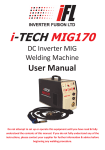
i-TECH MIG150 Inverter MIG Welding Machine User Manual Do not attempt to set up or operate this equipment until you have read & fully understood the contents of this manual. If you do not fully understand any of the instructions, please contact your supplier for further information & advice before beginning any welding procedure. Contents 1. General description .................................................................................. 1 2. Warranty .................................................................................................. 2 3. Safety ........................................................................................................ 2 4. Main parameters ...................................................................................... 3 5. Panel layout .............................................................................................. 4 6. Set up & operation ................................................................................... 6 7. Caution ................................................................................................... 11 8. Maintenance .......................................................................................... 11 9. Troubleshooting ..................................................................................... 12 1. General Description The i-TECH MIG150 welding machine is manufactured with advanced inverter technology. IGBT technology enhances the reliability of the machine. It is capable of MIG and scratch start TIG welding. High duty cycles enable continuous welding for longer periods. Closed loop feedback control, constant voltage output, workable under network voltage fluctuation within ± 15%. Adjustable welding voltage and circuit enable excellent welding characteristics. High no-load and slow wire feed functions increase the success rate of arc starting. 1 2. Warranty 1. Your i-TECH MIG150 welder is covered by a comprehensive 2 year return-tobase parts & labour warranty. 2. Improper use, abuse or any attempt to repair the product by an unauthorised third party will invalidate any warranty claim. 3. Any parts or consumables fitted or used in conjunction with the i-TECH MIG150 which affect the equipment operation & which are deemed by Inverter Fusion Ltd to be of inferior quality or not fit for that purpose will be regarded as abuse and will invalidate the warranty claim. 4. The claimant is responsible for all carriage, insurance and transportation costs in returning the product to Inverter Fusion Ltd. 5. Upon receipt and inspection of the product, it will be repaired or replaced at the discretion of Inverter Fusion Ltd. In the event of a chargeable repair, or a repair being required that is not considered to be a warranty issue, the claimant will be contacted for further instructions. 6. Following the completion of any authorised warranty claim work, the product will be returned to the claimant at the cost of Inverter Fusion Ltd (UK only). 3. Safety There are inherent safety issues whilst welding so please ensure you read this manual carefully before commencing operations and follow the safety guidelines below to protect yourself and others from injury: 1. Whilst welding, ensure that you are working in a well ventilated area to avoid breathing in smoke & fumes. 2. Always wear a suitable welding mask/helmet, welding gloves & protective clothing whilst welding. 3. Never look at the welding arc when not wearing a welding mask or helmet. 4. Never touch the work piece with bare hands whilst it is still hot. 5. When appropriate use a suitable welding screen or curtain to protect other people. 6. Do not weld near flammable materials or combustible liquids or gases. 7. Ensure the earth return is connected appropriately to prevent danger of electric shock. 8. Never touch moving parts on the machine, such as the fan, and ensure all doors, panels and covers are closed and in place during operation. 9. Magnetic fields produced by the welder during operation may affect cardiac pacemakers — pacemaker users should consult a doctor before welding. 2 4. Main Parameters Input Power Voltage 240 — 50/60Hz Current Range 20—150 Amps Open Circuit Voltage Range 22—31 Wire Feed Speed (m/min) 1—11 MIG Welding Wire (ø) 0.6—1.0mm 35% @ 150 Amps Duty Cycle @ 20° 60%@ 120 Amps 100% @ 100 Amps Power Factor 0.58 Efficiency 80% Protection Class IP21 Weight 11kg Dimensions 3 450mm x 203mm x 340 mm 5. Panel Layout 5.1. Front panel Power on indicator LED Overheating warning LED Wire speed adjustment Voltage adjustment Earth return Euro welding torch connector 4 5.2. Back panel Shielding gas hose connector Power on/off switch Input power cable 5.3. Internal panel structure Negative terminal 5 Positive terminal 6. Set Up & Operation Please ensure you follow these instructions whilst setting up your i-TECH MIG150: 6.1. Power cable connection Connect the power input lead to a suitable 240v single phase plug. 6.2. MIG welding with gas 6.2.1. Set up 1. Connect the welding torch to the output socket on the front panel of the machines and tighten it. 2. Connect the earth return to the negative (-) terminal on the front panel of the machine. 3. Insert the dix plug on the wire feeder into the “GAS” output socket on the internal panel and tighten it clockwise. 4. Fix the welding wire coil to the rack axis on the wire feeder, ensuring that the groove in the wire feed wheel is aligned with the torch wire feed hole. 5. Unfasten the tensioner on the wire-pressing wheel and feed the wire into the appropriate groove in the wire feed roller, pressing it in securely but not too tightly. NOTE: ensure the correct roller is fitted i.e. 0.8mm wire needs a 0.8mm groove on the roller. 6. Thread the wire into the welding torch manually and then press the wire feed button to feed it out of the end of the torch. 7. Connect the gas hose tightly to the regulator on the gas bottle. 6 6.2.2. Operation 1. Switch the power on at the back of the machine — the LED power indicator will light up and you will hear the fan start to work. 2. Open the gas cylinder valve and adjust the flow meter to the desired position. 3. Turn the conversion switch on the front of the machine to the “MIG welding” position and adjust the voltage and wire feed speed appropriately. 4. Adjust the burnback control on the internal panel to ensure the required length of wire protrudes out of the contact tip after welding. 5. Press the switch on the welding torch and begin welding. 6. The gas cuts off automatically one second after the arc is stopped. 6.3. MIG welding without gas 6.3.1. Set up 1. Connect the welding torch to the output socket on the front panel of the machines and tighten it. 2. Connect the earth return to the negative (-) terminal on the front panel of the machine. 3. Insert the dix plug on the wire feeder into the “NO GAS” output socket on the internal panel and tighten it clockwise. 4. Fix the welding wire coil to the rack axis on the wire feeder, ensuring that the groove in the wire feed wheel is aligned with the torch wire feed hole. 5. Unfasten the tensioner on the wire-pressing wheel and feed the wire into the appropriate groove in the wire feed roller, pressing it in securely but not too tightly. NOTE: ensure the correct roller is fitted i.e. 0.8mm wire needs a 0.8mm groove on the roller. 6. Thread the wire into the welding torch manually and then press the wire feed button to feed it out of the end of the torch. 7 6.3.2. Operation 1. Switch the power on at the back of the machine — the LED power indicator will light up and you will hear the fan start to work. 2. Turn the conversion switch on the front of the machine to the “MIG welding” position and adjust the voltage and wire feed speed appropriately. 3. Adjust the burnback control on the internal panel to ensure the required length of wire protrudes out of the contact tip after welding. 4. Press the switch on the welding torch and begin welding. 6.4. Changing the feed roll groove The feed roll groove is factory set for welding filler wires of 0.8-1.0mm diameter. The feed roll groove must be changed if you use 0.6mm filler wire. 1. Open the feed roll using the pressure control lever. 2. Switch the machine on from the main switch. 3. Press the welding gun trigger and drive the feed roll in such a position that the locking screw is up and can be opened. 4. Switch off the machine using the main power switch. 5. Open the feed roll locking screw by approximately half a turn using a 2.0mm Allen key. 6. Pull the feed roll from its shaft. 7. Turn the feed roll and reinstall it, making sure that the screw is on the same level as the shaft. 8. Tighten the feed roll locking screw. 8 6.5. Threading the filler wire 1. Open the reel housing by pressing the opening button and install the wire reel so that it rotates counter-clockwise. You can use either a 5kg (200mm diameter) or 1kg (100mm diameter) wire reel in the machine. 2. Attach the reel with a reel lock. 3. Unfasten the wire end from the reel, but keep hold of it. 4. Straighten the wire end for approximately 20cm and cut the wire in the straightened section. 5. Open the pressure control lever which then opens the feed gear. 6. Thread the wire through the wire’s rear guide to the gun’s wire guide. 7. Close the feed gear and fasten it with the pressure control lever. Make sure that the wire runs in the feed roll groove. 8. Adjust the compression pressure with the pressure control lever so that it is no higher than the middle of the scale. If the pressure is too high, it removes metal fragments from the wire surface and may damage the wire. On the other hand, 9 if the pressure is too low, the feed gear slips and the wire does not run smoothly. 9. Press the welding gun trigger and wait for the wire to come out. 10. Close the reel housing cover. CAUTION: When driving the wire into the gun, do not point the gun at yourself or others or put your hand in front of the tip, since the cut wire is extremely sharp. Keep fingers away from the feed rolls. 6.6. Reversing polarity (for gasless wire only) Some filler wires are recommended to be welded with the gun in the negative (-) pole. In this case, the polarity must be reversed. Consult the filler wire packaging for the recommended polarity. 1. Disconnect the machine from the mains. 2. Bend the rubber cover of the earthing cable’s pole in such a way that the cable can be disconnected. 3. Remove the nuts and washers. Note the correct order of the washers! 4. Interchange the cables. 5. Install the washers in place and close the tightening nuts to spanner tightness. 6. Put the rubber cover of the earthing cable’s pole firmly in place. The rubber cover must always protect the earthing cable’s pole. 10 7. Caution 7.1. Working environment 1. Welding should be carried out in a relatively dry environment with a humidity of 90% or less. 2. The temperature of the working environment should be -10°C to +40°C. 3. Avoid welding in the open air unless sheltered from sunlight and rain, and never let rain or water infiltrate the machine. 4. Avoid welding in dusty areas or where corrosive chemical gases are present. 5. Avoid MIG welding in environments with a strong airflow. 7.2. Ventilation The i-TECH MIG150 contains an inner fan which cools it effectively, enabling it to work steadily for longer periods. To enable the fan to work efficiently, always ensure that the louvers on the front panel are uncovered and unblocked and that the minimum distance between the machine and other objects is 30cm. 7.3. Overheating protection If the machine has become overheated because of continuous welding for long periods the overheat LED will light up and the overheat protection system will begin working, causing the machine to stop welding. If this occurs there is no need to restart the machine — once it has cooled down the LED will go out and welding can recommence. 8. Maintenance 1. Always use and store your i-TECH MIG150 in a clean, dry environment. 2. Regularly check that the cables and leads are in good condition. 3. Regularly check that the gas hose is in good condition and has no cracks. WARNING Improper use, abuse or any attempt to repair the product by an unauthorised third party will invalidate any warranty claim. Any parts or consumables fitted or used in conjunction with the i-TECH MIG150 which affect the equipment operation & which are deemed by Inverter Fusion Ltd to be of inferior quality or not fit for that purpose will be regarded as abuse and will invalidate the warranty claim. 11 9. Troubleshooting Fault Cause Remedy No mains power available Ensure that the machine is connected to a suitable live mains power source & is switched on The fuse in the plug is no longer working Replace the fuse The yellow LED light is lit The machine has overheated because the working duty cycle has been exceeded Stop welding for a while to allow the machine time to cool down. Ensure that the fan & output ducts are free from obstruction & that there is adequate ventilation space around the machine No welding output Welding leads are incorrectly fitted Check that the leads are fitted to the correct sockets & that the earth return is connected to the work piece MMA Welding operation is erratic or not as required Incorrect welding current selected Check that the current setting is correct for the selected electrode Faulty or damp electrode Select an alternative electrode The power on LED is not lit Erratic or Faulty electrode holder uncontrollable or bad earth return MMA welding arc connection Incorrect wire feed roller Incorrect feed roller MIG welding wire tension feed erratic Wire binding on reel Check that the correct sized components are fitted & that the electrode holder is in good condition. Ensure that there is a good earth return connection with the work piece Check correct size wire feed roller is fitted Check feed roller tension Check wire will easily feed from roll Nozzle blocked or wrong Check correct size nozzle is fitted in size torch 12 Heathpark Way, Heathpark Industrial Estate, Honiton, Devon, EX14 1BB 01404 549791 [email protected] | www.inverterfusion.co.uk Inverter Fusion Ltd @IFL_Welders