1
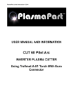
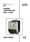
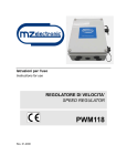
i-TECH CUT60 Inverter Plasma Cutter User Manual Do not attempt to set up or operate this equipment until you have read & fully understood the contents of this manual. If you do not fully understand any of the instructions, please contact your supplier for further information & advice before beginning any cutting procedure. Contents 1. General description .................................................................................. 1 2. Warranty .................................................................................................. 2 3. Safety ........................................................................................................ 2 4. Main parameters ...................................................................................... 3 5. Panel structures ....................................................................................... 4 6. Set up & operation ................................................................................... 6 7. Caution ..................................................................................................... 9 8. Maintenance ............................................................................................ 9 9. Troubleshooting ..................................................................................... 10 1. General Description The i-TECH CUT60 plasma cutter can be used for the easy and efficient cutting of all types of metal, including carbon steel, stainless steel and copper. It is manufactured using advanced inverter technology making it lightweight and highly portable. The latest MOFSET technology enhances the reliability of the machine. High duty cycles enable continuous cutting for longer periods. The arc-starting system uses high frequency DC, enabling an easier, smoother start. The smooth output current ensures even cutting. The noise level generated during cutting is very low. The robust casing is rated to IP23. 1 2. Warranty 1. Your i-TECH CUT60 welder is covered by a comprehensive 2 year return-to-base parts & labour warranty. 2. Improper use, abuse or any attempt to repair the product by an unauthorised third party will invalidate any warranty claim. 3. Any parts or consumables fitted or used in conjunction with the i-TECH CUT60 which affect the equipment operation & which are deemed by Inverter Fusion Ltd to be of inferior quality or not fit for that purpose will be regarded as abuse and will invalidate the warranty claim. 4. The claimant is responsible for all carriage, insurance and transportation costs in returning the product to Inverter Fusion Ltd. 5. Upon receipt and inspection of the product, it will be repaired or replaced at the discretion of Inverter Fusion Ltd. In the event of a chargeable repair, or a repair being required that is not considered to be a warranty issue, the claimant will be contacted for further instructions. 6. Following the completion of any authorised warranty claim work, the product will be returned to the claimant at the cost of Inverter Fusion Ltd (UK only). 3. Safety There are inherent safety issues whilst using a plasma cutter so please ensure you read this manual carefully before commencing operations and follow the safety guidelines below to protect yourself and others from injury: 1. Whilst cutting, ensure that you are working in a well ventilated area to avoid breathing in smoke & fumes. 2. Always wear a suitable protective mask/helmet, gloves & protective clothing whilst operating the machine. 3. Never look at the cutting arc when not wearing a mask or helmet. 4. Never touch the workpiece with bare hands whilst it is still hot. 5. When appropriate use a suitable welding/cutting screen or curtain to protect other people. 6. Do not operate the cutter near flammable materials or combustible liquids or gases. 7. Ensure the earth return is connected appropriately to prevent danger of electric shock. 8. Never touch moving parts on the machine such as the fan, and ensure all doors, panels and covers are closed and in place during operation. 9. Magnetic fields produced during operation may affect cardiac pacemakers — pacemaker users should consult a doctor before using the plasma cutter. 2 4. Main Parameters Power Voltage Single Phase 240V / 50/60Hz Input Power Capacity 9 KVA No—Load Voltage 230 V Output Current 60 Amps Output Voltage 120 Volts Duty Cycle Burner - Internal Diameter Power Factor 60% 1.2mm 0.93 Insulation Class B Protection Class IP23 Arc Starting Method HF / Contact Air Flow 0.25 m3/min Max Cutting Thickness 20mm Weight 16 kg Dimensions 3 480mm x 205mm x 357mm 5. Panel Structure 5.1. Front panel Air Pressure Gauge Power and Temperature indicator LEDs Post Air Time Control Current Setting Control Positive Terminal Torch Switch Plug Terminal Negative Terminal 4 5.2. Back panel Power Switch Power Input Regulator connection Water trap Air Input 5.3 i-TECH CUT60 with leads Safety Sleeve Torch Switch Cable/ Input Torch Earth Return 5 6. Set Up & Operation Please ensure you follow these instructions whilst setting up your i-TECH CUT60: 6.1. Power cable connection Connect the power input lead to a suitable 240v single phase plug. NOTE: If a longer mains cable is required please contact your supplier for specifications, as resistance from unsuitable additional cabling will affect cutting performance. 6.2. Set Up NOTE: The equipment MUST be off and disconnected from the power supply when being set up and/or checked. 6.2.1. Cutting Torch Assembly 1. Connect the brass fitting on the cutting torch to the negative output terminal on the front panel and cover with the safety sleeve. 2. Tighten clockwise to avoid air leakage. 3. Connect the switch plug of the cutting torch to the 2-pin socket on the front panel of the machine. Attach the cutting torch to the electrode, and fit the nozzle and the safety cap to the torch. 6.2.2. Earth Return 1. Connect the Earth Return to the positive output terminal on the front panel. 6.2.3. Air Regulator Installation 1. Connect the air hose from the compressor to the AIR IN point on the back of the machine. Connect the OUT hose tail on the regulator to the hose tail on the back of the machine. 2. Connect the orange pipe from the back of the machine to the regulator. 3. The air pressure should be set to between 4.5 and 5 bar. 4. Ensure that the water trap is emptied regularly and does not become overfull. 6 6.3. Start Up and Operation 6.3.1. Start Up 1. Switch on the power using the switch on the back panel. The LED power indicator will light up. 2. Set the pressure to the required value. The correct output pressure is critical both to the cutting performance and to optimise the machine’s lifespan. 3. Clamp the Earth Return to the work piece or to a metal workbench. 4. Depress the trigger on the cutting torch in order to check that air is released from the nozzle. 5. Set level of current according to the thickness and material type of the work piece. 6.3.2. Operation 1. Apply the torch nozzle to the work piece, and press the trigger to start the arc. Keeping the nozzle in contact with the work piece, start the cutting operation. 2. NOTE: If the plasma arc does not start on contact, check the connections on the electrode and nozzle. 3. Perform the cutting operation at an even speed, keeping the trigger depressed throughout. 4. To stop cutting, gradually reduce the cutting speed, and then release the trigger. 5. Any molten residue on the nozzle should be removed promptly. 6.4. Replacement of Electrode and Nozzle In order to prevent damage to the machine, the electrode and nozzle should be replaced if: 1. The nozzle becomes distorted. 2. A decline in cutting speed is experienced . 3. There is difficulty starting the arc, even after connections have been checked. 4. The cutting trace becomes irregular. IMPORTANT: Ensure the machine is switched off before replacing the electrode or nozzle. 7 7. Caution 7.1. Working environment 1. Plasma cutting should be carried out in a relatively dry environment with a humidity of 90% or less. 2. The temperature of the working environment should be -10°C to +40°C. 3. Avoid using the machine in the open air unless sheltered from sunlight and rain, and never let rain or water infiltrate the machine. 4. Avoid plasma cutting in dusty areas or where corrosive chemical gases are present. 5. Avoid using the Plasma Cutter in environments with a strong airflow. 7.2. Ventilation The i-TECH CUT60 contains an inner fan which cools it effectively, enabling it to work steadily for longer periods. To enable the fan to work efficiently, always ensure that the louvers on the front panel are uncovered and unblocked and that the minimum distance between the machine and other objects is 30cm. 7.3. Overheating protection If the machine has become overheated because of continuous cutting for long periods the temperature LED will light up and the overheat protection system will begin working, causing the machine to stop operating. If this occurs there is no need to restart the machine — once it has cooled down the LED will go out and cutting can recommence. 8. Maintenance 1. Always use and store your i-TECH CUT60 in a clean, dry environment. 2. Regularly check that the cables and leads are in good condition. 3. Regularly check that the air hose is in good condition and has no cracks. WARNING Improper use, abuse or any attempt to repair the product by an unauthorised third party will invalidate any warranty claim. Any parts or consumables fitted or used in conjunction with the i-TECH CUT60 which affect the equipment operation & which are deemed by Inverter Fusion Ltd to be of inferior quality or not fit for that purpose will be regarded as abuse and will invalidate the warranty claim. 8 9. Troubleshooting PROBLEM CAUSE Torch will not come Power switch OFF on Work piece Earth Clamp not attached Sparks are shooting upwards instead of down through the material. SOLUTION Turn power switch to ON position Attach to work piece or to steel table, with workpiece securely clamped to table. If flame appears more green than usual, air supply may be compromised. Check air supply Plasma torch is not piercing material Increase current Material may not be earthed properly Check earth return connections Travel speed too fast Reduce speed Torch may be too far away from the work piece Touch torch to work piece Beginning of cut not Possible connection problem completely pierced Check all connections Dross build-up on parts of cuts Allow material to cool then continue cut Tool/Material building up heat Cutting speed too low or current too high Arc stops while cutting 9 Increase speed and/or reduce current until dross is reduced to a minimum Worn torch parts Inspect and repair or replace worn parts Cutting speed too slow Increase speed until problem solved Torch is too high, away from material Touch torch to work piece Worn torch parts Inspect and repair/replace worn parts Work piece Earth cable disconnected Connect work piece Earth Clamp to work piece or steel table 9. Troubleshooting (cont’d) PROBLEM CAUSE SOLUTION Insufficient Penetration Cutting speed too fast Reduce travel speed Torch tilted too much Adjust tilt Metal too thick Several passes may be necessary Worn torch parts Inspect and repair or replace worn parts Unit capability is being exceeded Material too thick, increase angle to prevent blowback into torch tip Incorrectly assembled torch See section 6.2.1 ‘Torch Assembly’ Inadequate air supply, pressure too low Check air filter, increase air pressure Faulty air compressor Check air compressor operation and make sure input air pressure is in the range of 4.5—5 bar Consumables wear quickly 10 Heathpark Way, Heathpark Industrial Estate, Honiton, Devon, EX14 1BB. Tel: 01404 549791 | Fax: 01404 46718 | Email: [email protected] Website: www.inverterfusion.co.uk | Facebook: www.facebook.com/inverterfusionltd