1
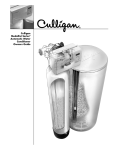
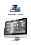
N21
AUTOMATIC CUBERS
OUR SYSTEMS CONFORM TO EC STANDARD 73/23 CEE - 89/336
SERVICE MANUAL
Cod. 71503341/0 - 3/00 - GB
PRODUTTORI DI GHIACCIO N 21 - ICE PRODUCTION N 21
PRODUCTION DE GLACE N 21- EIS PRODUCTION N 21
Temperatura acqua - Water temperature
Température eau - Wassertermperatur
°C
32°
21°
15°
10°
10°
17
20
22
23
kg
21°
16
19
21
22
kg
32°
14
17
19
20
kg
38°
13
16
18
17
kg
Prod. ghiaccio in 24 h - Ice prod. per 24 h
Prod. de glace en 24 h - Eisprod. in 24 h
RAFFREDAMENTO AD ARIA - AIR COOLED
REFR. A AIR - LUFTGEKÜHLT
Temperatura ambiente - Ambient temperature
Température ambiente - Raumtemperatur
Temperatura ambiente - Ambient temperature
Température ambiente - Raumtemperatur
RAFFREDAMENTO AD ACQUA - WATER COOLED
REFR. A EAU - WASSERGEKÜHLT
Temperatura acqua - Water temperature
Température eau - Wassertermperatur
°C
32°
21°
15°
10°
10°
17
20
22
23
kg
21°
16
19
21
22
kg
32°
14
17
19
20
kg
38°
13
16
18
17
kg
Prod. ghiaccio in 24 h - Ice prod. per 24 h
Prod. de glace en 24 h - Eisprod. in 24 h
(*) con temperatura ambiente 32 °C e con temperatura acqua 21 °C - with room temperature 32 °C and water temperature 21 °C
avec température ambiente 32 °C et température eau 21 °C - mit Raumtemperature 32 °C und Wassertemperatur 21 °C
SPECIFICHE TECNICHE - TECHNICAL SPECIFICATIONS
SPECIFICATIONS TECHNIQUES - TECHNISCHE ANGABEN
N 21
Alimentazione elettrica - Electric voltage - Alimentation électrique - Normale Netzpannung
Condensazione - Condensation - Condensation - Kühlung
N21 W
220-240/50/1
-10÷+6%
Aria - Air
Air - Luft
Acqua - Water
Eau - Wasser
Capacità contenitore (kg) - Bin Capacity (kg) - Capacité bac (kg) - Speiker Kapazität (kg)
6,5
Peso netto (kg) - Net weight (kg) - Poids net (kg) - Netto Gewicht (kg)
29
Potenza compressore CV - Compressor power HP - Puissance compresseur CV - Kompressorleistung PS
1/5
Amperaggio di marcia - Running amps - Ampérage en marche - Ampere
2.2
Amperaggio d’avv. - Start amps - Ampérage de démarr. - Start Ampere
9.1
Potenza - Power (Watts) - Puissance (Watts) - Leistung (Watt)
350
Consumo elettr. in 24 ore (Kwh) - Power cons. in 24 hrs (Kwh)
Cons. electr. en 24 hrs (Kwh) - Stromverbrauch in 24 std (Kwh)
7.5
Selezione cavi (mm2) - Wire size (mm2) - Section fils (mm2) - Kabelanzahl (mm2)
Carica refrig. R 134 a (gr) - Refrig. charge R 134 a (gr) - Charge refrig. R 134 a (gr) - Kühlmittel Füll. R 134 a(gr)
Dispositivo d’espansione - Refrigerant metering device - Détente du Rèfrigérant - Kältemittel-Expansionssystem
3x1
210
190
Tubo Capillare - Capillary tube
Tube capillaire - Kapillarrohor
PRESSIONI DI FUNZIONAMENTO - OPERATING PRESSURES
PRESSIONS DE FONCTIONNEMENT - BETRIEBSDRÜCKE
Pressione di mandata - Discharge pressure - Pressions de fonctionnement - Hochdruckbereich
Raffreddamento ad aria (21°C) - Air cooled (21°C) - Refroidissement par air (21°C) - Luftgekühlt (21°C)
Raffreddamento ad acqua - Water cooled - Refroidissement par eau - Wassergekühlt
N 21
8.5/7 bar
8/10 bar
Pressione di aspirazione - Suction pressure - Basse pression - Niederdrück
Fine ciclo di congelamento - End of freezing cycle - Fin cycle de congelation - Ende der Gefrierfase
1/0.2 bar
GB
GENERAL INFORMATION AND
INSTALLATION
A. INTRODUCTION
This manual provides the specification and the step-bystep procedures for the installation, start-up and operation, maintenance and cleaning for the Icemakers.
The machine cubers are quality designed, engineered
and manufactured.
Their ice making systems are thoroughly tested providing
the utmost in flexibility to fit the needs of a particular user.
This product qualifies for the following listings:
These icemakers have been engineered to our own rigid
safety and performance standards.
The VDE - SEV - WRC seals signifity that it is listed with
them and that it complies with the materials and manufacturing standard of them. These seals also signify that
these icemaker models have been inspectors who
reserve the right to periodically examine production icemakers at the factory to assure continued compliance.
5. Remove all internal support packing and masking
tape.
6. Check that refrigerant lines do not rub against or touch
other lines or surfaces, and that then fan blades move
freely.
7. Check that the compressor fits snugly onto all its
mounting pads.
8. See data plate on the rear side of the unit and check
that local main voltage corresponds with the voltage
specified on it.
CAUTION. Incorrect voltage supplied to the icemark will void your parts replacement program.
9. Remove the manufacturer’s registation card from the
inside of the User Manual and filling all parts including:
Model and Serial Number taken from the data plate.
Forward the completed self-addressed registration
card to the factory.
C. LOCATION AND LEVELLING
WARNING.
NOTE. To retain the safety and performance built into
this icemaker, it is important that installation and maintenance be conducted in the manner outlinde in this
manual.
B. UNPACKING AND INSPECTION
1. Call your authorized Distributor or Dealer for proper
installation.
2. Visually inspect the exterior of the packing and skid.
Any severe damage noted should be reported to the
delivering carrier and a concealed damage claim form
filled in subjetto inspection of the contents with the carrier’s representative present.
3.
a) Cut and remove the plastic strip securing the carton
box to the skid.
b) Remove the packing nails securing the carton box to
the skid.
c) Cut open the top of the carton and remove the polystyre protection sheet.
d) Pull out the polystyre posts from the corners and then
remove the carton.
1. Position the storage bin in the selected permanent
location.
Criteria for selection of location include:
a) Minimum room temperature 10°C (50°F) and maximun room temperature 40°C (100°F).
b) Water inlet temperatures: minimum 5°C (40°F) and
maximum 40°C (100°F).
c) Well ventilated location for air cooled models (clean
the air cooled condenser at frequent intervals).
d) Service access: adequate space must be left for all
service connections through the rear of the ice
maker. A minimum clearance of 15 cm (6”) must be
left at the sides of the unit for routing cooling air
draw into and exhausted out of the compartment to
maintain proper condensing operation of air cooled
models.
NOTE. With the unit in “built-in” conditions, the ice
production is gradually reduced in respect to the levels shown in the graph, up to a maximum of 10% at
room temperatures higer than 32°C.
The daily ice-making capacity is directly related to the
condenser air inlet temperature, water temperature
and age of the machine.
To keep your CUBER at peak performance levels,
periodic maintenance checks must be carried out as
indicates on this manual.
4. Remove the front and the sides panels of the unit and
inspect for any concealed damage. Notify carrier of
your claim for the concealed damage as stated in step
2 above.
17
GB
2. Level the Icemaker in both the left to right and front to
rear directions by means of the adjustable legs.
D. ELECTRICAL CONNECTIONS
See data plate for current requirements to determine wire
size to be used for electrical connections. All icemakers
require a solid earth wire.
All ice machines are supplied from the factory completely
pre-wired and require only electrical power connections to
the wire cord provided at the rear of the unit.
Make sure that ice machine is connected to its own circuit
and individually fused (see data plate for fuse size).
The maximum allowable voltage variation should not
exceed -10% and +6% of the data plate rating. Low voltage can ucause faulty functioning and may be responsible for serious damage to overload switch and motor
windings.
NOTE. All external wiring should conform to national,
state and local standards and regulations.
Check voltage on the line and the ice maker’s data plate
before connecting the unit.
E. WATER SUPPLY AND DRAIN
CONNECTIONS
GENERAL
When choosing the water supply for ice flaker consideration should be given to:
a) Length of run
b) Water clarity and purity
c) Adequate water supply pressure
18
Since water is the most important single ingredient in producing ice you cannot emphasize too much the three
items listed above.
Low water pressure, below 1 bar may cause malfunction
of the ice maker unit.
Water containing excessive minerals will tend to produce
cloudy colored ice cubes, plus scale build-up on the inerior parts of the water system.
WATER SUPPLY
Connect the 3/4” GAS male of the water inlet fitting, using
the food grade flexible tubing supplied with the machine,
to the cold water supply line with regular plumbing fitting
and a shut-off valve installed in an accessible position
between the water supply line with regular plumbing fitting
and a shut-off valve installed in an accessible position
between the water supply line and the unit.
If water contains a high level of impurities, it is advisable
to consider the installation of an appropriate water filter or
conditioner.
WATER DRAIN
Connect the drain fitting with a plastic tube to an open
trapped and vented drain. When the drain is a long run,
allow 3 cm pitch per meter (1/4” pitch per foot).
On water cooled versions, the water drain line from the
condenser is internally connected with the drain fitting of
the unit.
It is strongly recommended therefore to install a vertical
open vent on unit drain line high point to ensure good
draining and to direct the drain line to a trapped and vented floor drain receptacle
NOTE. The water supply and the water drain must be
installed to conform with the local code. In some case
a licensed plumber and/or a plumbing permit is
required.
GB
F. FINAL CHECK LIST
1.
Is the unit in a room where ambient temperatures are
within a minimum of 10°C (50°F) even in winter
months?
2.
Is there at least a 15 cm (6”) clearance arround the
unit for proper air circulation?
3.
Is the unit level? (IMPORTANT)
4.
Have all the electrical and plumbing connections
been made, and is the water supply shut-off valve
open?
5.
Has the voltage been tested and checked against the
data plate raiting?
6.
Has the water supply pressure been checked to
ensure a water pressure of at least 1 bar (14 psi).
7.
Have the bolts holding the compressor down been
checked to ensure that the compressor is snugly fitted onto the mounting pads?
8.
Check all refrigerant lines and conduit lines to guard
against vibrations and possible failure.
9.
Have the bin liner and cabinet been wiped clean?
10. Has the owner/user been given the User Manual and
been instructed on the importance of periodic maintenance checks?
11. Has the Manufacturer’s registration card been filled in
properly? Check for correct model and serial nuber
against the serial plate and mail the registration card
to the factory.
12. Has the owner been given the name and the phone
number of the authorized Service Agency serving
him?
G. INSTALLATION PRACTICE
1. Hand shut-off valve
2. Water filter
3. Water supply line (flexible hose)
4. 3/4” GAS male fitting
5. Vented drain
6. Open trapped vented drain
7. Drain fitting
8. Main switch
9. Power line
WARNING This icemaker is not designed for outdoor installation and will not function in ambient temperatures below 10°C (50°F) or above 40°C (100°F).
This icemaker will malfunction with water temperatures below 5°C (40°F) or above 40°C (100°F).
19
GB
OPERATING INSTRUCTIONS
OPERATIONAL CHECKS
START UP
C. At completion of the water filling phase the unit initiate
automatically the first freezing cycle with the start up of
(Fig.1):
After having correctly installed the ice maker and completed the plumbing and electrical connections, perform
the following "Start-up" procedure.
A. The model N 21 has to be operated by switching "on"
the master switch on the power line or, in case this last
one has not been fitted, by merely plugging in its electric cord into an adequate receptacle.
NOTE. The icemaker control is factory set with the
timer microswitches actuators dropped off into the initial point of the cam slot. This setting position allows a
proper water filling.
The unit starts operating in the "defrost cycle" with the following components being activated:
THE
THE
THE
THE
WATER INLET SOLENOID VALVE
HOT GAS SOLENOID VALVE
COMPRESSOR
TIMER MOTOR
B. During the water filling operation, check to see that the
incoming water dribblers, through the evaporator platen dribbler holes, down into the sump reservoir to fill it
up and also that the incoming surplus of water flows
out through the overflow pipe into the drain line.
NOTE. If, in the defrost cycle length, the machine
sump reservoir does not get filled with water up to the
rim of the overflow pipe, remove the front panel and
rotate the shaft of the timer so to cause the dropping
of the two microswitches actuators into the beginning
of the cam slot and check for:
1. The water pressure of the water supply line, it must
be at least 1 bar (14 psig) Minimum (Max 5 bar-70
psig).
2. The filtering device installed in the water line that
may reduce the water pressure below the Minimum
value of 1 bar (14 psig).
3. Any clogging situation in the water circuit like the
inlet water strainer and/or the flow control.
20
COMPRESSOR
WATER PUMP
FAN MOTOR (in air cooled version)
D. Check to see through the ice discharge opening that
the spray system is correctly seated and that the water
jets uniformely reach the interior of the inverted mold
cups or the exterior of the evaporator tips; also make
sure that the plastic curtain is hanging freely and there
is not excessive water spilling through it.
E. The ice making process takes place thereby, with the
water sprayed into the molds oron to the tips that gets
gradually refrigerated by the heat exchange with the
refrigerant flowing into the evaporator serpentine.
During the first portion of the freezing cycle, the timer
assy is standing-by with its microswitches actuators
resting on the raised cam profile (position that correspond to the end of the defrost cycle).
F. Then, as the cube size control cut-in point is Reached
by the evaporator temperature the control of the cycle
is passed to the timer assy. Whose raised cam slowly
rotates to continue the freezing cycle (2nd phase) up
to its completition.
The components in operation during this 2nd phase of
the cycle are (Fig.2):
COMPRESSOR
WATER PUMP
FAN MOTOR (in air cooled version)
TIMER MOTOR
G. After about 18÷20 minutes from the beginning of the
freezing cycle, in an hypothetic ambient temperature of
21°C, the defrost cycle takes place with the hot gas
and the water in let valves being simoultaneously activated.
The electrical components in operation are (Fig.3):
COMPRESSOR
WATER INLET SOLENOID VALVE
HOT GAS VALVE
TIMER MOTOR
H. Check, during the defrost cycle, that the incoming
water flows correctly into the sump reservoir in order to
refill it and that the surplus overflows through the overflow drain tube.
GB
I. Check the texture of ice cubes just released.
They have to be of the right size with a thickness of
about 7÷8 mm.
If the ice cubes have not the correct size, wait for a
second harvest before attempting any adjustment by
setting the cube size control.
By rotating the control setting screw clockwise the ice
cube thickness can be increased; on the contrary the
thickness can be reduced by turning the setting screw
counterclockwise.
If the ice cubes are shallow and cloudy, it is possible
that the ice maker runs short phase or, the quality of
the supplied water requires the use of an appropriate
water filter or conditioner.
J. With the icemaker in the harvest cycle, hold ice against
the bin thermostat control bulb to test its shut off
(Fig.4). This should cause the ice maker to shut OFF
after 30 seconds, 1 minute at the most, namely when
the control bulb temperature drops to reach + 1°C.
NOTE. In case this test is performed during the freezing cycle, the unit will shut OFF only at the end of the
freezing cycle and exactly when the timer switch actuatours drop-off into the cam slot (Fig. 5)
Within minutes after the ice is removed from the sensing
bulb, the bulb will warm up to reach +4°C and consequently will cause the icemaker to restart from the harvest
(defrost) cycle.
K. Instruct the owner/user on the general operation of
the general operation of the ice machine and about
the cleaning and care it requires.
21
GB
PRINCIPLE OF OPERATION
In the cube ice makers the water used to make the ice is
kept constantly in circulation by an electric water pump
which primes it to the spray system nozzles from where it
is diverted into the molds of the evaporator. A smoll quantity of the evaporator.
A small quantity of the sprayed water freezes into ice; the
rest of it cascades by gravity into the sump assembly
below for recirculation.
FREEZING CYCLE
The hot gas refrigerant discharged out from the compressor reaches the condenser where, being coole down, condenses into liquid. Flowing into the liquid line it passes
through the drier filter, then it goes all the way throught the
capillary tube where, due to the heat exchanging action, it
looses some of its heat content so that its pressure and
temperature are lowered as well.
Next the refrigerant enters into the evaporator serpentine
(which has a larger I.D. then the capillary) and starts to
boil off; this reaction is emphasized by the heat tranferred
by the sprayed water.
The refrigerant then increases in volume and changes
entirely into vapor.
The vapor refrigerant then passes throught the suction
accumulator (used to prevent that any small amount of liquid refrigerant may reach the compressor) and through
the suction line. In both the accumulator and the suction
line it exchanges heat with the refrigerant flowing into the
capillary tube (warmer), before to be sucked inthe compressor and to be recirculated as hot compressed refrigerant gas.
The freezing cycle is controlled by the evaporator thermostat (Which has its bulb in contact with the evaporator serpentine) that determines the length of its portion of the
cycle.
When the temperature of the evaporator thermostat
changes its concts (from 3-4 to 3-2) suppling power to the
finishing timer that takes the control of the second timed
portion of the control of the second timed portion of the
freezing cycle up to its completion.
The length of this second timed portion of the freezing
cycle is pre-fixed and related to the setting of the upper
part of the timer cam.
The refriferant head pressure, in the course of the freezing cycle, ranges between 9/7 bars.
On the air cooled version, the FAN MOTOR. Is working
during freezing cycle.
On the water cooled version the same hi-pressure control
is used to itermittently energize a water cooled version,
the discharge pressure is kept constant by the water regulating valve that meters the water flow to the condenser.
NOTE. In case of shortage of water to the condenser
or failure of the water solenoid valve a second “safety“ condenser thermostat, with the bulb in contact with
the tube of the liquid refrigerant, switch OFF the unit
operation as soon as its temperature reaches 35°C
(150°F).
The unit will resume automatically its operation when
the temperature of the condenser thermostat bulb
drops down by 10°C (18°F).
At the start of the freezing cycle the refrigerant suction or
lo-pressure lowers papidly to 1 bar then it declines gradually - in relation with the growing of the ice thickness - to
reach, at the end of the cycle, approx. 0,2 bar with the
cubes fully formed in the cup molds.
The total length of the freezing cycle range from 18 to 20
minutes.
DEFROST OR HARVEST CYCLE
As the electric timer has carried the system throughhout
the second phase of frezing cycle, the defrost cycle starts.
NOTE. The length of the defrost cycle is predetermined by the setting of the lower portion of the timer
cam.
In case it is possible to modify the defrost cucle length
through its setting screw.
ATTENTION. The defrost period is the most critical for the icemaker main components expecially
the compressor. To avoid to abuse of them it is
strongly recommended to limit the harvest cycle
extension to 4 minutes at the most.
The electrical components in operation during the freezing cycle are:
COMPRESSOR
FAN MOTOR (in air cooled versio)
WATER PUMP
CONCATROR COIL
and during the second phase of freezing cycle (Time
mode) they are joined by the TIMER
22
The electrical components in operation during this phase
are:
COMPRESSOR
WATER INLET SOLENOID VALVE
HOT GAS SOLENOID VALVE
TIMER MOTOR
GB
The incoming water, passing through the water inlet valve
and in its incorporated flow control (outlet), runs over the
evaporator platen and then flows by gravity through the
dribbler holes down into the sump/reservoir.
The water filling the sump/reservoir forces part of the leftover water from the previous batch to run out to the waste
through the overflow pipe. This overflow limits the level of
thesump water which will be used to produce the next
batch of ice cubes.
Meanwhile, the refrigerant as hot gas, discharged from
the compressor, flows through the hot gas valve directly
into the evaporator serpentine bypassing the condenser.
The hot gas circulating into the serpentine of the evaporator warms up the ice cubes. The ice cubes, released
from the molds, drop by garvity onto a slanted grid chute,
then through a curtained opening they fall into the storage
bin.
At the end of the defrost cycle, bith the hot gas and the
water inlet valves close and the machine starts again a
new freezing cycle.
BEGINNING FREEZE
Electrical components (Loads) .......
Compressor ........................................
Fan motor ...........................................
Hot gas valve......................................
Water inlet valve .................................
Water pump ........................................
Relay coil ............................................
Timer motor ........................................
ON
■
■
Electric Controls...............................
Conctats 3-4 evaporator thermostat...
Conctats 3-2 evaporator thermostat...
Bin thermostat ....................................
Conctats COM-NO timer microswitch
Conctats COM-NC timer microswitch.
Pressure control .................................
ON
■
OFF
■
■
■
■
■
OFF
■
■
■
■
■
OPERATION - CONTROL SEQUENCE
At the start of freezing cycle, the evaporator thermostat
controls the length of the firts part of predetermined temperature, it closes its contacts to supply power to the
timer motor which, in turn, takes over the control of the
setting extension of the cam high profile.
NOTE. The evaporator thermostat is factory set to the
number 4 of its setting dial.
In case it is required the setting of the evaporator thermostat can be made by turning its adjusting screw
located on front side. With a clockwise rotation of the
setting screw the thermostat cut IN temperature will
be lowered (longer freezing cycle - thicker ice cube)
while, with a counterclockwise rotation of the screw,
the Cut IN temperature rises (shorter freezing cycle thiner ice cube).
Once completed the freezing cycle 2nd phase the system
switches automatically into the defrost cycle which has a
pre-fixed length as well.
At completion of the defrost period the unit starts again a
new freezing cycle.
TIMED FREEZE
Electrical components (Loads) .......
Compressor ........................................
Fan motor ...........................................
Hot gas valve......................................
Water inlet valve .................................
Water pump ........................................
Relay coil ............................................
Timer motor ........................................
ON
■
■
Electric Controls...............................
Conctats 3-4 evaporator thermostat...
Conctats 3-2 evaporator thermostat...
Bin thermostat ....................................
Conctats COM-NO timer microswitch
Conctats COM-NC timer microswitch.
Pressure control .................................
ON
OPERATION - ELECTRICAL SEQUENCE
I° PORTION HARVEST CYCLE
The following charts illustrate which switches and which
components are ON or OFF during a particular phase of
the icemaking cycle.
Refer to the wiring diagram for a reference.
Electrical components (Loads) .......
Compressor ........................................
Fan motor ...........................................
Hot gas valve......................................
Waetr inlet valve .................................
Water pump ........................................
Relay coil ............................................
Timer motor ........................................
NOTE. The wiring diagram shows the unit as it is in
the Evaporator Thermostat mode of the Freezing
Cycle.
OFF
■
■
■
■
■
■
OFF
■
■
■
■
ON
■
■
■
OFF
■
■
■
■
■
■
23
GB
Electric Controls...............................
Conctats 3-4 evaporator thermostat...
Conctats 3-2 evaporator thermostat...
Bin thermostat ....................................
Conctats COM-NO timer microswitch
Conctats COM-NC timer microswitch.
Pressure control .................................
ON
OFF
■
■
■
■
■
■
II° PORTION HARVEST CYCLE
Electrical components (Loads) .......
Compressor ........................................
Fan motor ...........................................
Hot gas valve......................................
Water inlet valve .................................
Water pump ........................................
Relay coil ............................................
Timer motor ........................................
ON
■
Electric Controls...............................
Conctats 3-4 evaporator thermostat...
Conctats 3-2 evaporator thermostat...
Bin thermostat ....................................
Conctats COM-NO timer microswitch
Conctats COM-NC timer microswitch.
Pressure control .................................
ON
■
OFF
■
■
■
■
■
■
OFF
■
■
■
■
The bin thermostat, which has its sensing bulb downward
into the storage bin, shuts-OFF automatically the icemaker when the ice storage bin is filled and ice contacts its
bulb. Being it connected in series with the front
microswitch of the timer, it causes the unit shut-off only at
the end of the freezing cycle, when the ice cubes are completed.
After ice is removed from the bin and its bulb warm-up it
allows the unit to restart from the beginning of the harvest
cycle which, in the circumstance, is more likely a water filling cycle.
C. TIMER
Equipped with two microswitches which plungers ride one
timer cam, the timer is located inside the control box. The
function of the timer begins when activated by the cube
size control (evap. thermostat).
The large diameter lobe, determines the 2nd freezing
cycle portion length, while the cam small diameter lobe,
determines the time cycle for the harvest sequence. The
timer cam can be adjusted to vary the defrost time as
required.
WARNING. Never set the defrost time for longer
than 4 minutes as this will jeopardize the compressor motor windings.
■
OPERATING CHARACTERISTICS
On air cooled models during the freezing cycle the discharge pressure is between 9 and 7 bars.
At the same time the suctionpressure will gradually
decline, reaching its lowest point just before harvest.
Compressor amps experience a similar drop. On water
cooled, the discharge pressure is maintained constant
during the freeze cycle by the water regulating valve at 8
bars.
However, suction pressure and compressor amps will still
decline as the machine freezes ice.
COMPONENTS DESCRIPTION
A. EVAPORATOR THERMOSTAT
The evaporator thermostat with its sensing bulb intimately in contact with the refrigerant outlet tube from the evaporator, senses the evaporating refrigerant temperature
(wich declines in the one reaches the pre-set value, it
switches its contacts from 3-4 to 3-2 to activate the finishing cycle (2nd phase) which has a pre-set extension
determined by the large diameter lobe of the timer cam.
24
B. BIN THERMOSTAT
It goes without saying that an extension of the defrost
period will directly reduce the timed portion of the freezing
cycle and and viceversa.
Consequently any variation made at the timer cam setting
requires a compensation adjustment, very fine and very
accurate, of the evaporator thermostat.
D. HI PRESSURE CONTROL
Used on water cooled ice makers it functions to maintain
the head pressure within the present values of 8 and 10
bars, by intermittently activating the water inlet valve to
the condenser (in the water cooled models).
E. HI TEMPERATURE SAFETY THERMOSTAT
(Water air cooled models)
Fastened directly onto the refrigerant liquid line and electrically connected upstream all other controls, this safety
thermostat shut-off the icemakers when senses that the
temperature at the liquid line has rised to the limit of 65°C.
F. WATER SPRAY SYSTEM
It consists of on spray bar with several spray nozzles on
its extension.
GB
The water pumped, is sprayed throught its nozzles in
each individual mold or onto each evaporator tip to be
frozen into ice.
L. FAN MOTOR (Air cooled version)
The fan motor, operates during the freezing cycle to draw
cooling air through the condenser fins so to keep the condensing pressure between the 9/7 bars values.
G. WATER PUMP
The water pump operates continually throughout the
freezing cycle.
The pump primes the water from the sump to the spray it
to the copper molds or onto the evaporator tips to be
frozen into crystel clear ice cubes.
It si reccommended that the pump motor bearings be
checked at least every six months.
H. WATER INLET SOLENOID VALVE 3/4 MALE FITTING
The water inlet solenoid valve is activasted by the timer
microswitch only during the defrodt cycle. When energized it allows a metered amount of incoming water to
flow over the evaporator cavity to assist the hot gas in
defrosting the ice cubes. The water running over evaporator cavity drops by gravity, through the dribbler holes of
the plated, into the sump reservoir where it will be spray
system.
I. HOT GAS SOLENOID VALVE
The hot gas solenoid valve consists basically in two parts:
the valve body and the valve coil.
Located on the hot gas line, this valve is enerized through
the timer microswitch conctats COM-NC during the
defrost cycle.
During the defrost cycle the hot gas valve coil is activated
so to attract the hot gas discharged from compressor to
flow directly into the evaporator serpentine to defrost the
formed ice cubes.
M. WATER INLET SOLENID VALVE 3/4 MALE FITTING
N 21 (water cooled version)
A second water inlet solenoid valve, operating through an
automatic hi-pressure control, is used on water cooled
versions to supply water to the condenser.
When activated it supplies a metered amount of water to
the condenser in order to limit its temperature and the
refrigerant operating high pressure.
N. WATER REGULATING VALVE
(Water cooled version)
This valve controls the head pressure in the refrigerant
system by regulating the flow of water going to the condenser.
As pressure increases, the water regulating valve opens
to increases, the water regulating valve opens to increase
the flow of cooling water.
O. COMPRESSOR
The hermetic compressor is the heart of the refrigerant
system and it is used to circulate and retrieve the refrigerant throughout the entire system. It compresses the low
pressure refrigerant vapor causing its temperature to rise
and become high pressure hot vapor which is then
released through the discharge valve.
25
GB
SERVICE DIAGNOSIS
SYMPTOM
POSSIBLE CAUSE
SUGGESTED CORRECTION
Unit will not run
Main switch in OFF position
Turn switch to ON position
Loose electrical connections
Check wiring
Inoperative bin thermostat
Replace thermostat
Low voltage
Check circuit for overloading
Check vltage at the supply to
the building. If low, contact the
power company
Contactor with burnt contacts
Clean or replace
Non-condensable gas in system
Purge the system
Compressor starting device
with loose wires
Check for loose wires in starting
device
To high room temperature
Move the unit in a more
suitable place
Freezing cycle too short
Review setting of DIP SWITCH
keys
Capillary tube partially restricted
Blow charge, add new
gas & drier, after evacuating
system with vacumm pump
Moisture in the system
Same as above
Shortage of water
See remedies for shortage pf water
Shortage of refrigerant
Check for leaks & recharge
Inoperative evaporator thermostat
Replace thermostat
Shortage of water
See remedies for shortage of water
Dirty water supply
Use water sofner or water filter
Accumulated impurites
Use acid citric
Water pump loosing disch. pressure
Checkbearings. Replace.
Water spilling out through curtain
Check or replace curtain
Water solenoid valve not opening
Replace valve
Water leak in sump area
Locate and repair
Water flow control plugged
Remove and clean
Compressor cycles
intermittently
Cubes too small
Cloudy cubes
Shortage of water
26
GB
SERVICE DIAGNOSIS
SYMPTOM
POSSIBLE CAUSE
SUGGESTED CORRECTION
Irregular cubes
size & some cloudy
Some jets plugged
Remove jet cover and clean
Shortage of water
See shortage of water
Unit not level
Level as required
Freezing cycle too long
Adjust evap. thermostat
Inoperative evaporator thermostat
Replace thermosta
Inefficient compressor
Replace
Leaky water valve
Repair or replace
Non-condensable gas in system
Purge the system
Poor air circulation or excessive
hot location
(Red-alarm LED glows)
Relocate yhe unit or provide for
more ventilation
Overcharge of refrigerant
Correct the charge. Purge off slowly
Capillary tube partially restricted
Blow charge, add new gas & drier,
after evacuating system with
vascuu pump
Hot gas solenoid valve leaking
Replace valve
Undercharge of refrigerant
Charge to data plate indication
Discharge head pressure too high
See incorrect discharge pressure
Restriction incoming water line
Check water valve striner and flow
control. If necessary enlarge the flow
control orifice
Water inlet valve not opening
Valve coil with open winding
Replace valve
Hot gas valve orifice restricted
Replace hot gas valve assy
Discharge head pressure too low
See incorrect discharge pressure
Inoperative fan pressure control
Replace pressostat
Inoperative fan motor
Replace
Water regulating valve misadjusted
Adjust its setting stem
Water tubing leaking
Check. Tighten or replace
Cubes too large
Decreased ice capacity
Poor harvest
Incorrect discharge pressure
Excessive water in unit base
27
GB
MAINTENANCE AND
CLEANING INSTRUCTIONS
A. GENERAL
The periods and the procedures for maintenance and
cleaning are given as guides and are not to be construed
as absolute or invariable.
Cleaning, especially, will vary depending upon local water
and ambient conditions and the ive volume produced;
and, each icemaker must be maintened individually, in
accordance with its particular location requirements.
B. ICEMAKER
The following maintance should be scheduled at least two
times per year on these icemakers.
1. Check and clean the water line strainer.
2. Check that the icemaker is levelled in side to side and
in front to rear directions.
3. Clean the water system, evaporator, bin and spray jets
using a solution of Ice Machine Cleaner. (Acid citric)
Refer to procedure C cleaning instrutions and after
cleaning instructions and after cleaning will indicate
frequency and procedure to be followed in local areas.
NOTE. Cleaning requirements vary according to the
local water conditions and individual user operation.
Continuous check of the clarity of ice cubes and visual inspection of the water spraying parts before and
after cleaning will indicate frequency and procedure to
be followed in local areas.
4. With the ice machine and fan motor OFF on air cooled
models, clean condenser using vacuum cleaner, whisk
broom or non metallic brush taking care to do not damage both the condenser and ambient temperature sensors.
5. Check for water leaks and tighten drain line connections. Pour water down bin drain line to be sure that
drain line is open and clear.
6. Check size, condition and texture of ice cubes.
Perform adjustment of the evaporator thermostat or
cube size control by turning its adjusting screw clockwise for a thicker ice cube and counterclockwise for a
thiner one.
7. Check the bin thermostat to test shut-off. Put a handfull of ice cubes in contact with its bulb. This should
cause the ice maker to shut off within 20÷30”.
NOTE. Perform the above check only at the beginning
oh the harvest cycle as, during the freezing cycle the
bin thermostat contacts are bypassed by the front
microswitch of the timer.
28
When remove the ice cubes from its sensing bulb the unit
will restart after few seconds from the defrost cycle assuring the filling up of the water tank.
NOTE. It is possible tu adjust the setting temperature
of the bin thermostat by slihtly turning its adjusting
screw.
8. Check for refrigerant leaks.
C. CLEANING INSTRUCTIONS OF WATER
SYSTEM
1. Remove the front and the top panels to gain access
either to the control box and to the evaporator.
2. Wait till the end of defrost cycle then, OFF the machine
with the master switch on power line.
3. Scoop out all the ice cubes stored into the bin in order
to prevent from being contaminated with the cleaning
solution then flush out the water from the sump reservoir by removing the overflow stand-pipe.
4. Prepare the cleaning solution by diluting ina plastic
container two or three liters of warm water (45°÷ 50°
C) with a 0,2 ÷ 0,3 liters of Ice Machine Cleaner.
5. Remove the evaporator cover then slowly pour onto
the evaporator platen teh cleaning solution. With the
help of a brush dissolve the most resistant and remote
scale deposits in the platen.
6. Set the cleaning switch (where fitted) on CLEANING
position and give power to the unit by the master
switch (Fig. 6).
NOTE. With the system in CLEANING mode the
water pump is the only component in operation to circulate the cleaning solution in the entire water system.
On the model N. 21, with non cleaning switch, even
the compressor will be energized; this will partially
limit the descaling effect of the cleaning solution.
7. Let the unit to remain in the CLEANING mode for
about 20 minutes the switch OFF the machine.
8. Flush out the cleaning solution from the sump reservoir then pour onto the evaporator cavity one or two
liters of clean potable water with a capfull of antibacteria solution to rinse and sanitize the molds and the
spray system.
If necessary remove the spary bar and nozzles to
clean them separately then refit them.
9. Set back the master switch to ON. The water pump is
again in operation to circulate the water and the
antibacterial solution in order to rinse the entire water
system.
GB
Switch OFF the unit after approx. 10 minutes and flush
out the rinsing water from the sump reservoir.
10.Move the cleaning switch on RINSING position and
give power to the unit by the master switch (Fig. 7).
By doing so both water pump and the water inlet valve
are energized to fill up the water tank.
11. When the water tank in filled up (water flowing out from
the drain) put the cleaning switch on OPERATION
position to restart the machine in the automatic mode.
12.Re-fit the evaporator cover and the unit service panels.
13.At completion of the freezing and harvest cycle make
sure of proper texture and clearness of the ice cubes
and that, they do not have any acid taste.
ATENTION. In case the ice cubes are cloudy, white
and have and acid taste, melt them immediately
by pouring on them some warn water.
This to prevent somebody from using them.
14.Wipe clean and rinse the inner surfaces of the storage
bin.
REMEMBER. To prevent tthe accumulation of undesirable bacteria it is necesary to sanitize the interior
of the storage bin with an anti-algae disinfectant
solution every week.
29
GB
ELECTRIC DIAGRAM N21
30