1
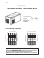
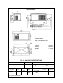
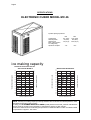
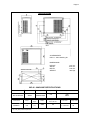
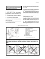
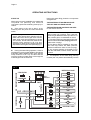
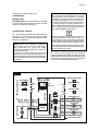
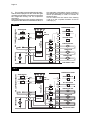
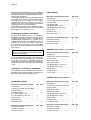
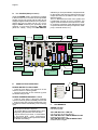
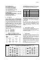
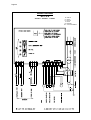
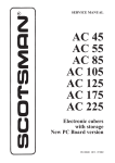
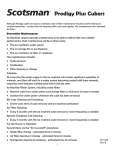
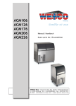
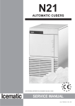
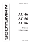
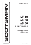
Page 1
Page 1
SERVICE MANUAL
MC 16
MC 46
Electronic
modular cubers
MS 1002.02 REV. 01/2007
Page 2
TABLE OF
CONTENTS
Page 2
Table of contents
Specifications MC 16
Specifications MC 46
2
3
5
GENERAL INFORMATION AND INSTALLATION
Introduction
Unpacking and Inspection - Ice maker
Unpacking and Inspection - Storage bin
Location and levelling
Stacking installation
Electrical connections
Water supply and drain connections
Final check list
Installation practice
7
7
7
7
8
9
9
10
10
OPERATING INSTRUCTIONS
Start up
Operatiobnal checks
11
12
OPERATING PRINCIPLES (How it works)
Freezing cycle
Harvest cycle
Control sequence
Component description
16
18
19
20
ADJUSTMENT, REMOVAL AND REPLACEMENT PROCEDURES
Adjustment of the cube size
Wiring diagram
Service diagnosis
24
25
29
MAINTENANCE AND CLEANING INSTRUCTIONS
General
Icemaker
Cleaning instructions of water system
31
31
32
Page 3
Page 3
SPECIFICATIONS
ELECTRONIC MODULAR CUBER MODEL MC 16
Important operating requirements:
Air temperature
Water temperature
Water pressure
Electr. voltage variations
from voltage rating
specified on nameplate
MIN.
10°C (50°F)
5°C (40°C)
1 bar (14 psi)
MAX.
40°C (100°F)
35°C (90°F)
5 bars (70 psi)
-10%
+10%
ice making capacity
MODÈLES REFROIDIS PAR AIR
AIR
AIRCOOLED
COOLEDMODELS
MODELS
MODÈLES REFROIDIS PAR EAU
WATER COOLED MODELS
Kg.
170
10
21
170
160
150
140
32
130
38
120
110
100
90
°C
10
21
32
38
160
150
140
130
120
110
100
90
80
80
32
27
21
15
WATER TEMPERATURE
TEMPÉRATURE DE L'EAU
10 °C
32
27
21
15
10 °C
WATER
TEMPERATURE
TEMPÉRATURE
DE L'EAU
NOTE. The daily ice-making capacity is directly related to the condenser air inlet temperature, water
temperature and age of the machine.
To keep your SCOTSMAN MODULAR CUBER at peak performance levels, periodic maintenance
checks must be carried out as indicated on maintenance section of this manual.
Production charts shown are indicating the production of MCM and MCL models. For MCS models
ice production is approx. 10% lower.
AMBIENT TEMPERATURE
TEMPÉRATURE
AMBIANTE
180
ICE PRODUCED
PER 24
PRODUCTION
DE GLACE
ENHRS
24 H
°C
AMBIENT TEMPERATURE
TEMPÉRATURE
AMBIANTE
PRODUCTION
DE GLACE
24 H
ICE
PRODUCED
PER 24EN
HRS
Kg.
180
Page 4
Page 4
SPECIFICATIONS
ACCESSORIES
KSC 11: Cube stacking kit
DIMENSIONS:
HEIGHT
WIDTH
DEPTH
WEIGHT
513 mm.
1074 mm.
534 mm.
117 Kgs.
MC 16 - MACHINE SPECIFICATIONS
Model
Cond. unit
Finish
Comp. HP
MC 16 AS 6B
MC 16 WS 6B
Air
Water
Stainless steel
Stainless steel
1.5
Basic electr.
230/50/1N
220-230/50/1
400/50/3N
Amps
Starts
amps.
5.5
7
32
Water req. - lt/24 HR
300
1700*
Watts
Electric power cons.
Kwh x 24 HR
N. of wires
1250
25.7
3 x 1.5 m/m2
5 x 1.5 m/m2
Cubes per harvest: MCL-16 72 large - MCM-16 102 medium - MCS 16 198 small
* At 15°C (60°F) water temperature
Amps. fuse
20
10
3x
Page 5
Page 5
SPECIFICATIONS
ELECTRONIC CUBER MODEL MC 46
Important operating requirements:
Air temperature
Water temperature
Water pressure
Electr. voltage variations
from voltage rating
specified on nameplate
MIN.
10°C (50°F)
5°C (40°C)
1 bar (14 psi)
MAX.
40°C (100°F)
35°C (90°F)
5 bars (70 psi)
-10%
+10%
ice making capacity
MODÈLES REFROIDIS PAR AIR
AIR COOLED MODELS
MODÈLES REFROIDIS PAR EAU
WATER COOLED MODELS
°C
300
10
300
10
290
21
290
21
280
32
270
38
280
270
260
32
250
240
230
38
220
210
ICE PRODUCED
PEREN
24 24
HRS
PRODUCTION
DE GLACE
H
310
260
250
240
230
220
210
200
200
190
190
180
32
27
21
15
WATER TEMPERATURE
TEMPÉRATURE DE L'EAU
10 °C
180
32
27
21
15
10 °C
WATER TEMPERATURE
TEMPÉRATURE DE L'EAU
NOTE. The daily ice-making capacity is directly related to the condenser air inlet temperature, water
temperature and age of the machine.
To keep your SCOTSMAN MODULAR CUBER at peak performance levels, periodic maintenance
checks must be carried out as indicated on maintenance section of this manual.
Production charts shown are indicating the production of MCM and MCL models. For MCS models
ice production is approx. 10% lower.
AMBIENT TEMPERATURE
TEMPÉRATURE
AMBIANTE
Kg.
°C
AMBIENT TEMPERATURE
TEMPÉRATURE
AMBIANTE
PRODUCTION
DE GLACE
ENHRS
24 H
ICE PRODUCED
PER 24
Kg.
310
Page 6
Page 6
SPECIFICATIONS
ACCESSORIES
KSC 11: Cube stacking kit
DIMENSIONS:
HEIGHT
WIDTH
DEPTH
WEIGHT
874 mm.
1074 mm.
534 mm.
185 Kgs.
MC 46 - MACHINE SPECIFICATIONS
Model
Cond. unit
Finish
Comp. HP
MC 46 AS 6B
MC 46 WS 6B
Air
Water
Stainless steel
Stainless steel
2.5
Basic electr.
230/50/1N
220-230/50/1
400/50/3N
Water req. - lt/24 HR
660
2800*
Amps
Starts
amps.
Watts
Electric power cons.
Kwh x 24 HR
N. of wires
10
7
5.5
66
14
2400
50
3 x 1.5 m/m2
5 x 1.5 m/m2
Cubes per harvest: MCL-46 144 large - MCM-46 204 medium - MCS 46 396 small
* At 15°C (60°F) water temperature
Amps. fuse
20
10
3x
Page 7
Page 7
GENERAL INFORMATION AND INSTALLATION
A.
INTRODUCTION
This manual provides the specifications and the
step-by-step procedures for the installation, startup and operation, maintenance and cleaning for
the SCOTSMAN MODULAR CUBERS.
The Electronic Modular Cubers are quality
designed, engineered and manufactured.
Their ice making systems are thoroughly tested
providing the utmost in flexibility to fit the needs
of a particular user.
These icemakers have been engineered to our
own rigid safety and performence standards.
NOTE. To retain the safety and performance
built into this icemaker, it is important that
installation and maintenance be conducted
in the manner outlined in this manual.
Storage Bin
Since the MC series Modular Cubers do not
have their own attached ice storage bins, it is
necessary to use an auxiliary bin such as the Bin
B 350 or B 550.
B.
UNPACKING AND INSPECTION
Modular Cuber
1. Call your authorized SCOTSMAN Distributor
or Dealer for proper installation.
2. Visually inspect the exterior of the packing
and skid. Any severe damage noted should be
reported to the delivering carrier and a concealed
damage claim form filled in subjet to inspection
of the contents with the carrier’s representative
present.
3. a) Cut and remove the plastic strip securing
the carton box to the skid.
b) Remove the packing nails securing the
carton box to the skid.
c) Cut open the top of the carton and remove
the polystyre protection sheet.
d) Pull out the polystyre posts from the
corners and then remove the carton.
4. Remove top and sides panels of the unit
and inspect for any concealed damage. Notify
carrier of your claim for the concealed damage
as stated in step 2 above.
5. Loose two nuts on left and rights side of the
unit base and remove it from the skid. Save the
two bolts and nuts to mount the machine on
storage bin or on top of another Modular Cuber.
6. Remove all internal support packing and
masking tape and the hardware package.
7. Check that refrigerant lines do not rub
against or touch other lines or surfaces, and that
the fan blade moveS freely.
8. Check that the compressor fits snugly onto
all its mounting pads.
9. See data plate on the rear side of the unit
and check that local main voltage corresponds
with the voltage specified on it.
CAUTION. Incorrect voltage supplied to
the icemaker will void your parts
replacement program.
10. Remove the manufacturer’s registration
card from the inside of the User Manual and fillin all parts including: Model and Serial Number
taken from the data plate.
Forward the completed self-addressed
registration card to Frimont/Scotsman Europe
factory.
Storage bin
1. Follow the steps 1, 2 and 3 above to unpack
the storage bin.
2. Unloose the two bolts and remove the
protection plate from the drain fitting.
3. Carefully lay it down on its rear side and fit
the four legs into their sockets.
4. Remove all internal support packing and
masking tape as well as the plastic ice cube
deflector.
5. Remove the manufacturer’s registration
card from the inside of the User Manual and fillin all parts including: Model and Serial Number
taken from the data plate.
Forward the completed self-addressed
registration card to Frimont/Scotsman Europe
factory.
C.
LOCATION AND LEVELLING
WARNING. This Ice Cuber is designed for
indoor installation only. Extended periods
of operation at temperature exceeding
the following limitations will constitute
misuse under the terms of the SCOTSMAN
Manufacturer’s Limited Warranty
resulting in LOSS of warranty coverage.
Page 8
1. Position the Bin in the selected permanent
location. Criteria for selection of location include:
a) Minimum room temperature 10°C (50°F)
and maximum room temperature 40°C (100°F).
b) Water inlet temperatures: minimum 5°C
(40°F) and maximum 35°C (90°F).
c) Well ventilated location for air cooled
models.
d) Service access: adequate space must be
left for all service connections through the rear of
the ice maker. A minimum clearance of 15 cm
(6") must be left at the sides of the unit for routing
cooling air drawn into and exhausted out of the
compartment to maintain proper condensing
operation of air cooled models.
2. Level the Storage Bin Assy in both the left
to right and front to rear directions by means of
the adjustable legs.
3. Inspect the Storage Bin top mounting gasket
which should be flat with no wrinkles, to provide
a good sealing when the Modular Cuber is
installed on top of it.
4. Place the Modular Cuber on top of Storage
bin using care not to wrinkle or tear the gasket.
5. Lift a little bit the Modular Cuber right side in
order to be able to mount the ice level control
bracket taking care to align the hole located on
unit base to mate with the one on the top of the
Bin.
6. Remove the PVC plastic plug closing the
round hole located on the right side of the ice
chute opening.
7. Trace the ice level control assy, secured for
the transport on top of the evaporator of the
Modular Cuber, and direct it down through the
round hole into the Storage Bin.
8. Fasten the ice level control assy on its
bracket by means of the two screws found in the
hardware package supplied with the unit.
9. Make a cut (shear) in the PVC plastic plug
that goes from its edge to the center; insert the
ice level control cable in the center of the plastic
plug so to prevent it from any sort of contact with
the unit frame, then place again the PVC plug in
the round hole keeping the cable exceeding
portion inside the unit.
Page 8
D.
ISTACKING INSTALLATION
A Stacking Kit KSC 11 is available as an
accessory on request to allow the installation of
two Modular Cubers one on top of the other.
The Stacking Kit is consisting of:
a) a plastic reinforced Ice Chute Connection
b) an Interface P.C. Board
enabling to cover any stacking installation
combination as:
a) MC 16-46 on top of MC 15-45.
b) MC 16-46 on top of MC 16-46.
1. Unloose the four screws and remove the
top panel of bottom machine.
2. Remove the two plastic plugs from the upper
edges of the two side frames of the bottom unit.
3. Install the MC 16/46 cuber on top of the
MC 15/45 or MC 16/46 placing the four rubber
corner plates between the two machines.
4. Secure them by bolts and nuts supplied
with the machine.
5. Remove the ice chute from both the unit
and insert, through the ice discharge opening of
the upper unit, the plastic reinforced Ice Chute
Connection.
6. In case of installation over an MC 45/46
install the additional ice chute connection supplied
in the kit.
ATTENTION. The PC Boards installed on
the two machines as well as the interface
PC Board supplied in the KSC 11 Kit must
be of the same supplier (Syen or
Pro.EI.Ind.).
If not the unit with the different one
remains OFF at storage bin full.
7.
Disconnect the ice level control terminal
plug from the P.C. Board of the upper Modular
Cuber (now colled secondary).
8. Secure the interface P.C. Board to the
contactor metal bracket of the lower unit (now
called primary) by means of the supplied plastic
clamp.
9. Disconnect the ice level control terminal
plug from the P.C. Board of the primary unit and
connect it to the INLET socket of the interface
P.C. Board (shorter wire).
10. Install the plastic ice cube deflector by
hooking it on the flange of the ice chute opening
in unit base (see illustration).
10. Connect the primary OUTLET terminal
plug of the Interface P.C. Board (wire of medium
lenght) to the P.C. Board socket of the primary
unit.
11. Secure the Modular Cuber on the top of the
Storage Bin using the two bolts and diber washer
found in the hardware package supplied with the
unit.
11. Connect the secondary OUTLET plug
(longer wire) of the interface P.C. Board to the
P.C. Board socket of the secondary unit (see
drawing).
Page 9
12. Turn the TRIMMER setting screw (located
on the front center of P.C. Board) of the ice level
control of the secondary unit clockwise to its
maximum power (Only on Syen type).
Page 9
The maximum allowable voltage variation should
not exceed -10% and +10% of the data plate
rating. Low voltage can cause faulty functioning
and may be responsible for serious damage to
the overload switch and motor windings.
NOTE. All external wiring should conform to
national, state and local standards and
regulations.
Check voltage on the line and the ice maker’s
data plate before connecting the unit.
E.
WATER SUPPLY AND DRAIN
CONNECTIONS
General
When choosing the water supply for the ice
flaker consideration should be given to:
a) Length of run
b) Water clarity and purity
c) Adequate water supply pressure
Since water is the most important single ingredient
in producting ice you cannot emphasize too
much the three items listed above.
Low water pressure, below 1 bar may cause
malfunction of the ice maker unit.
Water containing excessive minerals will tend to
produce cloudy coloured ice cubes, plus scale
build-up on parts of the water system.
13. The interface P.C. Board is now ready to
stop simultaneously the operation of the two
units when the infrared beam of the ice level
control is interrupted by the stored ice cubes.
ATTENTION. After removal of the ice cubes
both units resume their operation starting
from the beginning of freezing cycle.
During the first freezing cycle it could be
posible that the ice cubes produced by
one of the two ice makers be not of correct
shape (cloudy and shallow) due to an
insufficient water level in its sump tank.
This minor problem will desappear in the
next batch because in the harvest cycle
the sump tank will be properly filled-up.
14. Place again in their position the two ice
chutes and finally re-fit the service panels
previously removed.
E.
ELECTRICAL CONNECTIONS
See data plate for current requirements to
determine wire size to be used for electrical
connections. All SCOTSMAN icemakers require
a solid earth wire.
All SCOTSMAN ice machines are supplied from
the factory completely pre-wired and require only
electrical power connections to the wire cord
provided at the rear of the unit.
Make sure that the ice machine is connected to
its own circuit and individually fused (see data
plate for fuse size).
Water supply
Connect the 3/4" GAS male fitting of the solenoid
water inlet valve, using flexible tubing or a 3/8"
O.D. copper pipe, to the cold water supply line
with regular plumbing fitting and a shut-off valve
installed in an accessible position between the
water supply line and the unit.
Water supply - Water cooled models
The water cooled versions of SCOTSMAN Ice
Makers require two separate inlet water supplies,
one for the water sprayed for making the ice
cubes and the other for the water cooled
condenser.
Connect the 3/4" GAS male fitting of the water
inlet, using the flexible tubing or a 3/8" O.D.
copper pipe, to the cold water supply line with
regular plumbing fitting and a shut-off valve
installed in an accessible position between the
water supply line and the unit.
Water drain
The recommended drain tube is a plastic or
flexible tube with 18 mm (3/4") I.D. which runs to
an open trapped and vented drain. When the
drain is a long run, allow 3 cm pitch per meter
(1/4" pitch per foot).
A vent at the unit drain connection is also required
for proper sump drainage.
Water drain - Water cooled models
Connect the 3/4" GAS male fitting of the
condenser water drain, utilizing a second flexible
tubing or a 3/8" O.D. copper tubing, to the open
trapped and vented drain.
Page 10
Page 10
NOTE. The water supply and the water drain
must be installed to conform with the local
code. In some case a licensed plumber and/
or a plumbing permit is required.
F.
FINAL CHECK LIST
1. Is the unit in a room where ambient
temperatures are within a minimum of 10°C
(50°F) even in winter months?
2. Is there at least a 15 cm (6") clearance
around the unit for proper air circulation?
3.
Is the unit level? (IMPORTANT)
4. Have all the electrical and plumbing
connections been made, and is the water supply
shut-off valve open?
5. Has the voltage been tested and checked
against the data plate rating?
6. Has the water supply pressure been
checked to ensure a water pressure of at least 1
bar (14 psi).
7. Have the bolts holding the compressor down
been checked to ensure that the compressor is
snugly fitted onto the mounting pads?
8. Check all refrigerant lines and conduit lines
to guard against vibrations and possible failure.
9. Have the bin liner and cabinet been wiped
clean?
10. Has the owner/user been given the User
Manual and been instructed on the importance of
periodic maintenance checks?
11. Has the Manufacturer’s registration card
been filled in properly? Check for correct model
and serial number against the serial plate and
mail the registration card to the factory.
12. Has the owner been given the name and
the phone number of the authorized SCOTSMAN
Service Agency serving him?
G. INSTALLATION PRACTICE
1.
2.
3.
4.
5.
6.
7/9.
8/10.
11.
Hand shut-off valve
Water filter
Water supply line (flexible hose)
3/4" gas male fitting
Power line
Main switch
Drain fitting
Vented drain line
Open trapped vented drain
WARNING. This icemaker is not designed for outdoor installation and will not function in
ambient temperatures below 10°C (50°F) or above 40°C (100°F).
This icemaker will malfunction with water temperatures below 5°C (40°F) or above 35°C
(90°F).
Page 11
Page 11
OPERATING INSTRUCTIONS
During the water filling phase the components
energized are:
START UP
After having correctly installed the ice maker and
completed the plumbing and electrical
connections, perform the following “Start-up” procedure.
A. Give power to the unit to start it up by
switching "ON" the power line main disconnect
switch.
NOTE. Every time the unit returns under
power, after having been switched off, the
water inlet valve, the hot gas valve and the
water drain valve get energized for a period
of 5 minutes, thus to admit new water to the
machine sump reservoir to fill it up and,
eventually, to wash-off any dirt that can have
deposited in it during the unit off period (Fig.1).
B. During the water filling operation, check to
see that the incoming water dribbles, through the
evaporator platen dribbler holes, down into the
sump reservoir to fill it up and also that the
incoming surplus of water flows out through the
overflow pipe into the drain line.
THE WATER INLET SOLENOID VALVE
THE HOT GAS SOLENOID VALVE
THE WATER DRAIN SOLENOID VALVE/S
for the first 30 seconds.
NOTE. If in the 5 minutes length of the water
filling phase the machine sump reservoir
does not get filled with water up to the rim of
the overflow pipe, it is advisable to check:
1.The water pressure of the water supply line
that must be at least 1 bar (14 psig) Minimum
(Max 5 bar-70 psig).
2.The filtering device installed in the water
line that may reduce the water pressure
below the Minimum value of 1 bar (14 psig).
3. Any clogging situation in the water circuit
like the inlet water strainer and/or the flow
control.
C. At completion of the water filling phase (5
minutes) the unit passes automatically into the
FIG. 1
COMPRESSOR
16
DIP
SWITCH
- CONDENSER
15
- AMBIENT
14
Rx
Tx
13
L
1
N
2
ELECTR.
TIMER
DATA
PROCESSOR
BIN
TEMPERATURE SENSORS
WATER DRAIN VALVE
- EVAPORATOR
7
WATER IN VALVE
8
9
HOT GAS VALVE
10
RELAYS
3
CONTACTOR COIL
4
TRIAC
5
FAN MOTOR
6
TRANSF.
RELAY
WATER PUMP
11
12
ELECTRONIC CARD
Page 12
Page 12
freezing cycle with the start up of:
COMPRESSOR
WATER PUMP
FAN MOTOR/S (in air cooled version) controlled
by the condensing temperature sensor located
within the condenser fins (Fig.2).
In case of condenser clogging such to prevent
the proper flow of the cooling air or, in case
the fan motor is out of operation or shortage
of water in the water cooled condenser, the
condenser temperature rises and when it
reaches 70°C (160°F) - for air cooled version
- or 60°C (140°F) - for water cooled version the condenser temperature sensor shuts-off
the ice maker with the consequent light-up of
the RED WARNING LED (Fig.3).
OPERATIONAL CHECKS
D. If necessary install the refrigerant service
gauges on both the high side and low side
Schräder valves to check the compressor head
and suction pressures.
NOTE. On air cooled models the condenser
temperature sensor, which is located within
the condenser fins, keep the head
(condensing) pressure between 16 and 18
bars (225-250 psig).
In the water cooled models the discharge
pressure is kept constant at the value of 17
bars (240 psig) by means of a water regulating
valve located on the water supply line to the
condenser.
After having diagnosed the reason of the rise
of temperature and removed its cause, it is
necessary to unplug (wait few seconds) and
plug in again the unit, thus to put the machine
in condition to initiate a new freezing cycle.
The machine restarts with the usual 5 minutes
water filling phase in order to provide enough
water into the sump tank.
E. Check to see through the ice discharge
opening that the self propeller spray bar is correctly
rotating and that the water jets uniformely reach
the interior of the inverted mold cups and there is
not excessive water spilling through it.
FIG. 2
COMPRESSOR
16
DIP
SWITCH
- CONDENSER
15
- AMBIENT
14
Rx
Tx
13
L
1
N
2
ELECTR.
TIMER
DATA
PROCESSOR
BIN
TEMPERATURE SENSORS
WATER DRAIN VALVE
- EVAPORATOR
7
WATER IN VALVE
8
9
HOT GAS VALVE
10
RELAYS
3
CONTACTOR COIL
4
TRIAC
5
FAN MOTOR
6
TRANSF.
RELAY
WATER PUMP
11
12
ELECTRONIC CARD
Page 13
Page 13
F. The ice making process takes place thereby,
with the water sprayed into the molds that gets
gradually refrigerated by the heat exchange with
the refrigerant flowing into the evaporator
serpentine.
During the freezing process, when the evaporator
temperature falls below an established value, to
the evaporator temperature sensor supplies a
low voltage power signal to the electronic control
device (P.C.BOARD) in order to activate an
electronic timer.
This one takes over the control of the freezing
cycle up to the complete formation of the ice
cubes (Fig.4).
FIG. 3
- EVAPORATOR
16
DIP
SWITCH
- CONDENSER
- AMBIENT
14
Rx
Tx
13
L
1
N
2
ELECTR.
TIMER
DATA
PROCESSOR
15
COMPRESSOR
BIN
TEMPERATURE SENSORS
WATER DRAIN VALVE
7
WATER IN VALVE
8
9
HOT GAS VALVE
10
RELAYS
3
CONTACTOR COIL
4
TRIAC
5
FAN MOTOR
6
TRANSF.
RELAY
WATER PUMP
11
12
ELECTRONIC CARD
FIG. 4
COMPRESSOR
16
DIP
SWITCH
- CONDENSER
15
- AMBIENT
14
Rx
Tx
13
L
1
N
2
ELECTR.
TIMER
DATA
PROCESSOR
BIN
TEMPERATURE SENSORS
WATER DRAIN VALVE
- EVAPORATOR
7
WATER IN VALVE
8
9
HOT GAS VALVE
10
RELAYS
3
CONTACTOR COIL
4
TRIAC
5
FAN MOTOR
6
TRANSF.
RELAY
WATER PUMP
11
12
ELECTRONIC CARD
Page 14
Page 14
NOTE. The length of the entire freezing cycle
is governed by the evaporator temperature
sensor which has its brobe placed in contact
with the evaporator serpentine (Non
adjustable) in combination with the electronic
timer (Adjustable) incorporated in the P.C.
BOARD).
The timer adjustment is factory set in
consideration of the ice maker model, cooling
version and ice cube size (Small, Medium,
Large).
It is possible, however, to modify the timed
length of the freezing cycle, by changing the
DIP SWITCH keys setting.
In Table B of PRINCIPLE OF OPERATION
are shown the various time extensions of the
freezing cycle second phase, in relation with
the different DIP SWITCH keys settings.
G. After about 17-20 minutes from the
beginning of the freezing cycle, in an hypothetic
ambient temperature of 21°C , the defrost cycle
takes place with the hot gas and the water inlet
valves being simoultaneously activated (Fig.5).
The electrical components in operation are:
COMPRESSOR
WATER PUMP
WATER INLET SOLENOID VALVE
HOT GAS VALVE
WATER DRAIN SOLENOID VALVE/S
for the first 30 seconds.
NOTE. The length of the defrost cycle is
related to the length of the second phase of
freezing cycle T2. (Time to drop the
evaporating temperature from 0°C (32°F) small Red LED blinking-to-15°C (5°F) small
Red LED ON steady.
It is possible to extend the length of the defrost
cycle by changing the setting of DIP SWITCH
7 and 8 as shown on table at page 24.
H. Check, during the defrost cycle, that the
incoming water flows correctly into sump reservoir
in order to refill it and that the surplus overflows
through the overflow drain tube.
FIG. 5
COMPRESSOR
- EVAPORATOR
16
DIP
SWITCH
- CONDENSER
15
- AMBIENT
14
Rx
Tx
13
L
1
N
2
ELECTR.
TIMER
DATA
PROCESSOR
BIN
TEMPERATURE SENSORS
WATER DRAIN VALVE
7
WATER IN VALVE
8
9
HOT GAS VALVE
10
RELAYS
3
CONTACTOR COIL
4
TRIAC
5
FAN MOTOR
6
TRANSF.
RELAY
WATER PUMP
11
12
ELECTRONIC CARD
Page 15
Page 15
I.
Check the texture of ice cubes just released.
They have to be in the right shape with a small
depression of about 5-6 mm in their crown.
If not, wait for the completion of the second cycle
before performing any adjustment.
If required, the length of the timed freezing cycle
can be modified by changing the DIP SWITCH
keys setting as illustrated in OPERATING
PRINCIPLE.
If the ice cubes are shallow and cloudy, it is
possible that the ice maker runs short of water
during the freezing cycle second phase or, the
quality of the supplied water requires the use of
an appropriate water filter or conditioner.
J. To be sure of the correct operation of ice
level control device, place one hand between its
sensing “eyes” to interrupt the light beam.
The Bin Full YELLOW LED starts to blink, and
after 60 seconds, the unit stops with the
simultaneous glowing of the same LED to monitor the BIN FULL situation (Fig.6).
Take the hand out from the ice level control
sensors to allow the resumption of the light
beam.
The BIN FULL YELLOW LED blinks fast and
after approximately 6 seconds the ice maker
resume its operation with the immediate glowing
of the FIRST YELLOW LED indicating UNIT IN
OPERATION and the extinguishing of the “BIN
FULL” YELLOW LED.
NOTE. The ICE LEVEL CONTROL
(INFRARED SYSTEM) is independent of
the temperature however, the reliability of its
detection can be affected by external light
radiations or by any sort of dirt and scale
sediment which may deposit directly on the
light source and on the receiver.
To prevent any possible ice maker
malfunction, due to negative affection of the
light detertor, it is advisable to locate the unit
where it is not reached by any direct light
beam or light radiation, also it is recommended
to keep the bin door constantly closed and to
follow the instructions for the periodical
cleaning of the light sensor elements as
detailed in the MAINTENANCE AND
CLEANING PROCEDURES.
K. Remove, if previously installed, the
refrigerant service gauges and re-fit the unit
service panels previously removed.
L. Instruct the owner/user on the general
operation of the ice machine and about the
cleaning and care it requires.
FIG. 6
COMPRESSOR
16
DIP
SWITCH
- CONDENSER
15
- AMBIENT
14
Rx
Tx
13
L
1
N
2
ELECTR.
TIMER
DATA
PROCESSOR
BIN
TEMPERATURE SENSORS
WATER DRAIN VALVE
- EVAPORATOR
7
WATER IN VALVE
8
9
HOT GAS VALVE
10
RELAYS
3
CONTACTOR COIL
4
TRIAC
5
FAN MOTOR
6
TRANSF.
RELAY
WATER PUMP
11
12
ELECTRONIC CARD
Page 16
Page 16
PRINCIPLE OF OPERATION
When the temperature of the evaporator
serpentine drops to a pre-set value, the evaporator
sensor probe changes its electrical resistance
allowing a low voltage current (12 volts) to flow to
the P.C. BOARD which in turn activates an
electronic timer.
The timer, which is built-in the P.C. BOARD,
takes over from the evaporator temperature
sensor, the control of the freezing cycle up to its
completion.
How it works
In the SCOTSMAN Modular Cubers the water
used to make the ice is kept constantly in
circulation by an electric water pump which primes
it to the self propeller spray bar nozzles from
where it is diverted into the inverted mold cups of
the evaporator (Fig. B).
A small quantity of the sprayed water freezes into
ice; the rest of it cascades by gravity into the
sump assembly below for recirculation.
NOTE. The change of the electric potential of
the evaporator sensor with the consequent
activation of the timer (Time mode) is signalled
by the glowing-up of the RED LED located
beside the FREEZING yellow one in the front
of the P.C. BOARD.
FREEZING CYCLE (Fig. A)
The hot gas refrigerant discharged out from the
compressor reaches the condenser where, being
cooled down, condenses into liquid. Flowing into
the liquid line it passes through the drier filter,
then it goes all the way through the capillary tube
where, due to the heat exchanging action, it
looses some of its heat content so that its pressure
and temperature are lowered as well.
Next the refrigerant enters into the evaporator
serpentine (which has a larger I.D. then the
capillary) and starts to boil off; this reaction is
emphasized by the heat transferred by the
sprayed water.
The refrigerant then increases in volume and
changes entirely into vapor.
The vapor refrigerant then passes through the
suction accumulator (used to prevent that any
small amount of liquid refrigerant may reach the
compressor) and through the suction line. In both
the accumulator and the suction line it exchanges
heat with the refrigerant flowing into the capillary
tube (warmer), before to be sucked in the
compressor and to be recirculated as hot
compressed refrigerant gas.
The freezing cycle is controlled by the evaporator
temperature sensor (which has its probe in contact
with the evaporator serpentine) that determines
the length of its first portion of the cycle.
ATTENTION. In case, after 15 minutes
from the beginning of the freezing cycle,
the temperature of the evaporator sensor
probe is higher then 0°C (32°F) (shortage
of refrigerant, inoperative hot gas valve,
etc.) the P.C. BOARD switch OFF
immediately the
unit with the
simultaneous blinking of the WARNING
RED LED.
The length of this second portion of the freezing
cycle is pre-fixed and related to the setting of the
first four DIP SWITCH keys.
The DIP SWITCH keys setting is made in
consideration of the type of condenser used.
In Table B are indicated the various lengths of the
second portion of freezing cycle (Time mode) in
relation to the different combinations of the DIP
SWITCH KEYS.
In Table A herebelow are illustrated the DIP
SWITCH key combinations for the three different
factory.
TAB. A
DIP SWITCH FACTORY SETTING COMBINATIONS PER MODEL AND VERSION
FREEZING CYCLE
DIP SWITCH
MCS 16-46 A
MCS 16-46 W
MCM 16 A
MCM 16 W
MCM 46-1210 A
MCM 46-1210 W
MCL 16-46-1210 A
MCL 16-46-1210 W
MCXL 46 W
DEFROST CYCLE
DEFR. CYCLE
ADD. TIME
15/30°
AIR
WATER
1
2
3
4
5
6
7
8
9
10
ON
ON
OFF
ON
ON
OFF
ON
ON
OFF
OFF
OFF
ON
ON
ON
ON
ON
ON
ON
ON
ON
OFF
OFF
OFF
OFF
ON
ON
OFF
ON
ON
ON
ON
ON
ON
OFF
OFF
OFF
ON
ON
ON
ON
ON
ON
ON
ON
OFF
OFF
OFF
OFF
OFF
OFF
OFF
OFF
OFF
ON
ON
ON
ON
ON
ON
ON
ON
ON
ON
ON
ON
ON
ON
ON
ON
ON
ON
OFF
ON
ON
ON
ON
ON
ON
ON
ON
ON
ON
OFF
ON
OFF
ON
OFF
ON
OFF
OFF
Page 17
Page 17
Page 18
The electrical components in operation during
the freezing cycle are:
COMPRESSOR
FAN MOTOR (in air cooled version)
WATER PUMP
CONTACTOR COIL
and during the second phase of freezing cycle
(Time mode) they are joined by the
ELECTRONIC TIMER
The refrigerant head pressure, in the course of
the freezing cycle, ranges between 18 and 16
bars (250-225 psig) being controlled by the temperature sensor probe located within the
condenser fins (air cooled version) or, on the
condenser tube coil (water cooled version).
On the air cooled version, the condenser temperature sensor, when senses a rising of the
condenser temperature beyond the pre-fixed
limit, changes its electrical resistance and send a
low voltage power flow to the Micro Processor of
P.C. BOARD which in turn energizes, through a
TRIAC, the FAN MOTOR.
When the opposite situation occures, i.e. the
condenser temperature gets below the pre-fixed
limit, the temperature sensor changes again its
electrical resistance reducing therefore the current
flow to the P.C. BOARD to cause the fan motor
temporary cut-off.
NOTE. On this model the condenser sensors
are used just to switch off the unit in case the
condensing temperature rise up to more then
70°C (for air cooled version) or more then
62°C (for water cooled version) for one of the
following abnormal reasons:
CLOGGED CONDENSER (Air cooled
version)
FAN MOTOR OUT OF OPERATION (Air
cooled version)
INSUFFICIENT FLOW OF COOLING
WATER (Water cooled version)
AMBIENT TEMPERATURE HIGHER THEN
40°C (100°F)
it causes the total and immediate SHUT-OFF
of the machine in order to prevent the unit
from operating in abnormal and dangerous
conditions.
When the ice maker stops on account of this
protective device, there is a simultaneous
glowing of the RED LED, warning the user of
the Hi Temperature situation.
After having efiminated the source of the
condenser hi-temperature, to restart the
machine just switching OFF and ON the unit
at main line switch.
The ice machine resumes its normal operation
by going through the 5 minutes water filling
phase.
Page 18
At the start of the freezing cycle the refrigerant
suction or lo-pressure lowers rapidly to 2.5 bars35 psig then it declines gradually - in relation with
the growing of the ice thickness - to reach, at the
end of the cycle, approx. 1.6 ÷ 1.7 bar - 22 ÷ 24
psig with the cubes fully formed in the cup molds.
The total length of the freezing cycle ranges f rom
20 to 25 minutes.
DEFROST OR HARVEST CYCLE (Fig. D)
As the electronic timer has carried the system
throughout the second phase of freezing cycle,
the defrost cycle starts.
ATTENTION. In case the unit be able to
reach 0°C (32°F) evaporating temperature within 15 minutes, but after 45 minutes
from the beginning of the freezing cycle it
has not yet reached the evaporator temperature of -15°C (5°F) the machine goes
straight into the defrost cycle omitting
the timed portion of the freezing cycle
relied to the setting of the first four DIP
SWITCHES.
NOTE. The length of the defrost cycle is
related to the length of the second phase of
freezing cycle T2. (Time to drop the
evaporating temperature from 0°C (32°F) small Red LED blinking-to-15°C (5°F) small
Red LED ON steady.
It is possible to extend the length of the defrost
cycle by changing the setting of DIP SWITCH
7 and 8 as shown on table at page 24.
The electrical components in operation during
this phase are:
COMPRESSOR
CONTACTOR COIL
WATER INLET VALVE
HOT GAS VALVE
WATER DRAIN VALVE
and the
WATER PUMP
on the first 30 seconds.
The incoming water, passing through the water
inlet valve and the flow control, runs over the
evaporator platen and then flows by gravity
through the dribbler holes down into the sump/
reservoir (Fig. D).
The water filling the sump/reservoir forces part of
the surplus water from the previous freezing
cycle to go out to the waste through the overflow
pipe. This overflow limits the level of the sump
water which will be used to produce the next
batch of ice cubes.
Page 19
Page 19
Meanwhile, the refrigerant as hot gas, discharged
from the compressor, flows through the hot gas
valve directly into the evaporator serpentine bypassing the condenser.
The hot gas circulating into the serpentine of the
evaporator warms up the copper molds causing
the defrost of the ice cubes. The ice cubes,
released from the cups, drop by gravity onto a
slanted cube chute, then through a curtained
opening they fall into the storage bin.
At the end of the defrost cycle, both the hot gas
and the water inlet valves close and the machine
starts again a new freezing cycle.
OPERATION - CONTROL SEQUENCE
At the start of freezing cycle, the evaporator
temperature sensor controls the length of the
first part of the freezing cycle. As it reaches a
predetermined temperature, it supplies a low
voltage current to the P.C. BOARD in order to
activate the electronic timer which, takes over
the control of the freezing cycle for a pre-fixed
time, according to the DIP SWITCH keys setting
(see Tab. B).
TIMED FREEZE
Electrical components (Loads) .
Compressor ..................................
Fan Motor (Air cooled only) and TRIAC
Hot Gas Valve ..............................
Inlet Water Valve ..........................
P.C. Board Relay 1 Coil ...............
P.C. Board Relay 2 & 3 Coil .........
Water Pump .................................
Contactor Coil ..............................
Electronic Timer ...........................
Electronic Controls & Sensors .
Evaporator Sensor .......................
Condenser Sensor .......................
Ice Level Control ..........................
ON OFF
•
•
•
•
•
•
•
•
•
•
ON
OFF
•
•
•
•
HARVEST (Drain portion - first 30 sec.)
NOTE. The evaporator temperature sensor,
factory pre-set, is the same for all the models
and is not adjustable.
Once completed the freezing cycle 2nd phase
the system goes automatically into the defrost
cycle which also has a pre-fixed length. At
completion of the defrost cycle the P.C. BOARD
commands the unit to start again a new freezing
cycle.
OPERATION - ELECTRICAL SEQUENCE
The following charts illustrate which switches
and which components are ON or OFF during a
partÌcular phase of the icemaking cycle.
Electrical components (Loads) .
Compressor ..................................
Fan Motor (Air cooled only) and TRIAC .
Hot Gas Valve ..............................
Water Inlet Valve ..........................
Water Drain Valve ........................
P.C. Board Relay 1 & 2 Coil .........
P.C. Board Relay 3 Coil ...............
Water Pump .................................
Contactor Coil ..............................
P.C.B. Timer .................................
ON OFF
•
•
•
•
•
•
•
•
•
•
HARVEST (Water filling portion)
BEGINNIING FREEZE
Electrical components (Loads) .
Compressor ..................................
Fan Motor (Air cooled only) and TRIAC
Hot Gas Valve ..............................
Inlet Water Valve ..........................
P.C. Board Relay 1 Coil ...............
P.C. Board Relay 2 & 3 Coil .........
Water Pump .................................
Contactor Coil ..............................
Electronic Timer ...........................
ON OFF
•
•
•
•
•
•
•
•
•
Electronic Controls & Sensors .. ON OFF
Evaporator Sensor .......................
•
Condenser Sensor .......................
•
Ice Level Control ..........................
•
Electrical components (Loads) .
Compressor ..................................
Fan Motor (Air cooled only) and TRIAC .
Hot Gas Valve ..............................
Water Inlet Valve ..........................
Water Drain Valve ........................
P.C. Board Relay 1 & 2 Coil .........
P.C. Board Relay 3 Coil ...............
Water Pump .................................
Contactor Coil ..............................
P.C. Board Timer .........................
ON OFF
Electronic Controls & Sensors .
Evaporator Sensor .......................
Condenser Sensor .......................
Ice Level Control ..........................
ON OFF
•
•
•
•
•
•
•
•
•
•
•
•
•
Page 20
Page 20
Freeze Cycle
Average Discharge
Pressure A/C:
16÷18 bars (225÷250 psig)
Average Discharge
Pressure W/C:
17 bars (240 psig)
Suction Pressure End
Freeze Cycle:
1.6÷1.7 bar (22÷24 psig)
REFRIGERANT CHARGE (R 404 A)
MC 16
MC 46
MC 46 (60 Hz)
Air Cooled
640 gr
1300 gr
1040 gr
Water Cooled
500 gr
700 gr
560 gr
NOTE. Before charging the refrigerant system
always check the type of refrigerant and
quantity as specified on the individual ice
machine dataplate.
The refrigerant charges indicated are related
to average operating conditions.
WARNING. As R 404 a is a band of different
types of refrigerants it is imperative to
charge the system only in liquid phase in
order to avoid to alter their mix-up
percentage.
The activation of the electronic timer (-15°C 5°F) is monitored by the lighting up of the RED
LED placed in the front of the P.C. BOARD.
This lighting up occures usually in the mid period
of the freezing cycle and signals the switching
from the first to the second phase of the freezing
cycle.
NOTE. Whenever, after 15 minutes from the
beginning of the freezing cycle, the
evaporating temperature have not yet
reached the value of 0°C (32°F), the P.C.
BOARD switches OFF the machine with the
BLINKING of RED LED.
B.
CONDENSER TEMPERATURE SENSOR
The condenser temperature sensor probe,
located within the condenser fins (air cooled
version) or in contact with the tube coil (water
cooled version) detects the condenser temperature variations and signals them by supplying
current, at low voltage, to the P.C. BOARD.
In the air cooled versions, in relation to the
different current received, the micro processor of
the P.C. BOARD supplies, through a TRIAC, the
power at high voltage to the fan motor so to cool
the condenser and to reduce its temperature.
In case the condenser temperature rises and
reaches 70°C (1 60°F) - on air cooled models - or
62°C (145°F) - on water cooled models - the
current arriving to the micro processor is such to
cause an immediate and total stop of the machine
operation.
COMPONENTS DESCRIPTION
C.
A.
EVAPORATOR TEMPERATURE
SENSOR
The evaporator temperature sensor probe,
located in contact with the evaporator serpentine,
detects the dropping of the evaporator temperature during the freezing cycle and signals it by
supplying a current flow to the micro processor of
P.C. BOARD.
According to the current received, the evaporator
sensor supplies power to the P.C. BOARD first,
when it reachs 0°C (32°F), second at -15°C (5°F);
in this second case it supply power to the electronic
timer built into the P.C. BOARD so that it may
take control of the fength of the 2nd phase of
freezing cycle.
The length of the timed phase is pre-f ixed by the
setting of the keys 1, 2, 3 and 4 of the DIP
SWITCH.
ICE BIN LEVEL LIGHT CONTROL
The electronic ice bin level control, located into
the storage bin, has the function to stop the
operation of the ice machine when the light beam
between the light source and the sensor is
interrupted by the ice cubes stored into the bin.
When the light beam is interrupted the Bin Full
YELLOW LED starts to blink; in case the light
beam is constantly interrupted for more than 60
seconds, the ice machine stops with the glowingup of the Bin Full YELLOW LED to monitor the
situation of ice bin full.
The 60 seconds of delay prevent that an ice
scoop movement or the ice dropping through the
ice chute (interrupting for a while the light beam)
can stop the operation of the unit.
Six seconds after the scoop out of the ice (with
the resumption of the light beam between the two
infrared sensor of ice level control - YELLOW
LED blinks fast) the ice machine restarts again
with the extinguishing of the YELLOW LED.
Page 21
D.
Page 21
P.C. BOARD (Data processor)
The P.C. BOARD, fitted in its plastic box located
in the front of the unit, consists of two separated
printed circuits one at high and the other at low
voltage integrated with two fuses one on power in
(32mA) and one on power out (6.3 A), of four
aligned LEDS monitoring the operation of the
machine, of one extra monitoring RED LED
(blink 0°C - steady - 15°C), of one DIP SWITCH
MICROPROCESSOR
EPROM
EPROM
0°C-BLINKING
-13°C-STEADY
with ten keys, of one push button, of input terminals
for the leads of the sensor probes and input and
output terminals for the leads of the ice maker
electrical wires.
The P.C. BOARD is the brain of the system and
it elaborates, through its micro processor, the
signals received from the three sensors in order
to control the operation of the different electrical
components of the ice maker (compressor, water
pump, solenoid valves, etc.).
RESET PUSH BUTTON
TRIAC
TRIAC
FUSE
FUSE
FREEZING
TRANSFORMER
TRANSFORMER
ALARM
ALARM
WATER
PUMP
WATER
PUMP
RELAY
RELAY
BIN
BINFULL
FULL
COMPRESSOR
RELAY
RELAY
POWER
POWER
FUSE
FUSE
I/R ADJUSTER
RESISTANCE
RESISTANCE
VARISTOR
VARISTOR
EVAPORATOR
SENSOR SOCKET
CONDENSER
CONDENSER
SENSOR SOCKET
E.
OPTICAL ICE LEVEL
OPTICAL ICE LEVEL
CONTROLSENSOR
CONTROLSENSOR
SOCKET
SOCKET
TERMINAL
TERMINAL
BOARD
BOARD
PUSH
PUSH
BUTTON
BUTTON
PUSH BUTTON OPERATION
DURING WATER FILLING PHASE
• Push for more then 2” but less then 5” the
machine enters in Cleaning Mode
• Push for more then 5” the machine by-pass
the Water Filling Phase
DURING FREEZING/HARVEST CYCLE
• Push for more then 5” during the Freezing
cycle the machine goes immediately into Harvest
• Push for more then 5” during the Harvest cycle
the machine enters immediately in the Freezing
cycle
The length of Harvest is equal to:
• 35” if Push Button is activated before -15°C
evaporating temperature LED activation
• As per Harvest cycle chart, if Push Button
is activated after -15°C evaporating
temperature LED activation (Red LED inside
PC Board ON steady)
HOT GAS, WATER
INLET AND PURGE
VALVES RELAY
VALVES RELAY
FREEZING CYCLE
TOO HI COND TEMP
TOO HI EVAP TEMP
BIN FULL
POWER
F.
LED MEANING
GREEN LED ON
Unit under power
YELLOW BIN FULL LED ON
Unit shut-OFF at storage bin full
YELLOW BIN FULL LED BLINKING SLOW
Infrared beam break out
YELLOW BIN FULL LED BLINKING FAST
Infrared beam in again
Page 22
Page 22
The DIP SWITCH N° 7 and 8 allow the extention
of the length of the harvest/defrost cycle according
to their combination as per following chart:
RED ALARM LED ON
Too hi condensing temperature
RED ALARM LED BLINKING
Too hi evaporating temperature
YELLOW FREEZING CYCLE ON
Unit in freezing cycle mode
DIP SWITCH
YELLOW FREEZING OR BIN FULL AND RED
ALARM LED ON
Condenser sensor out of order
YELLOW FREEZING OR BIN FULL AND RED
ALARM LED BLINKING
Evaporator sensor out of order
G.
ADDITIONAL DEFROST TIME
7
8
ON
ON
0
OFF
ON
30"
ON
OFF
60"
OFF
OFF
90"
DIP SWITCH
The P.C.BOARD which controls the entire
operation of the ice maker, has a DIP SWITCH
with ten switching keys which allow to set up
the micro processor program in order to extend
or to shorten the length of freezing cycle in relation
to the different model and versions of ice machines.
The DIP SWITCH first four keys setting
determines the length of the 2nd phase of
freezing cycle (controlled by the electronic
timer) as detailed in the table B.
The DIP SWITCH keys 5 & 6 setting determines
the length of the defrost cycle according to the
size of the cubes (Large or Medium) as per the
following setting:
ON ON : PROGRAM A
ON OFF : PROGRAM B
OFF OFF : PROGRAM C
OFF ON : PROGRAM D
LENGTH OF HARVEST CYCLE
ACCORDING TO THE TIME TO DROP THE
EVAP. TEMPERATURE FROM 0°C TO -15°C
LENGTH
HARVEST
CYCLE
A
180”
Up to 6’30”
165”
6’30”-7’
150”
7’-8’
135”
8’-9’
120”
9’-10’30”
105”
10’30”-12’
90”
>12’
TAB. B
PROGRAMS
B
***
Up to 3’
3’-3’15’
3’15”-3’30”
3’30”-4’30”
4’30”-6’
>6’
C
Up to 9’30”
9’30”-10’
10’-11’
11’-12’
12’-13’30”
13’30”-15’
>15’
D
xxxx
xxxx
xxxx
xxxx
< 3'
3' - 4'
> 4'
The 9th key is used to supply power to the water
pump for the first 15 seconds of the defrost cycle
- position OFF - or for the first 30 seconds position ON.
The 10th key is used to modify the CUT-OUT
condensing temperature from 70°C (160°F) for
the air cooled versions - ON position - to 60°C
(140°F) - OFF position - for the water cooled
versions.
H. WATER SPRAY SYSTEM
Through its nozzles, the water pumped, is sprayed
in each individual cup to be frozen into ice.
It consists of one spray tube wheve are located
several spray nozzles.
I.
WATER PUMP
The water pump operates continually throughout
the freezing cycle and on the first 15 or 30
seconds of the defrost cycle so to such the
remaining water from the sump tank (reach in
mineral salts) and drain it out.
During the freezing cycle the pump primes the
water from the sump to the spray system and
through the spray nozzles sprays it into the
inverted cup molds to be frozen into crystal clear
ice cubes.
It is recommended that the pump motor bearings
be checked at least every six months.
LENGTH OF TIMED PORTION OF FREEZING CYCLE ACCORDING TO THE
DIP SWITCH SETTING COMBINATIONS
Page 23
J.
WATER INLET SOLENOID VALVE 3/4 GAS MALE FITTING
The water inlet solenoid valve is activated by the
micro processor of the P.C. BOARD during the
first 5 minutes of water filling phase and as well
during the defrost cycle.
When energized it allows a metered amount of
incoming water to flow overt he evaporator cavity
to assist the hot gas in defrosting the ice cubes.
The water running over the evaporator cavity
drops by gravity, through the dribbler holes of
the platen, into the sump reservoir where it will be
sucked by the water pump and primed to the
spray system.
K.
HOT GAS SOLENOID VALVE
The hot gas solenoid valve consists basically in
two parts: the valve body and the valve coil.
Located on the hot gas line, this valve is energized
through the micro processor of P.C. BOARD
during the defrost cycle and as well during the
water filling phase.
During the defrost cycle the hot gas valve coil is
activated so to attract the hot gas valve piston in
order to give way to the hot gas discharged from
the compressor to flow directly into the evaporator
serpentine to defrost the formed ice cubes.
L. FAN MOTOR (Alir cooled version)
The fan motor is controlled through the P.C.
BOARD and the TRIAC by the condenser temperature sensor. Normally it operates only during
the freezing cycle to draw cooling air through the
condenser fins.
In the second part of the freezing cycle, the fan
motor can run at intermittance as the condenser
pressure must be kept between two
corresponding head pressure values (16÷18 bars225÷250 psig).
Page 23
M.
COMPRESSOR
The hermetic compressor is the heart of the
refrigerant system and it is used to circulate and
retrieve the refrigerant throughout the entire
system. It compresses the low pressure
refrigerant vapor causing its temperature to rise
and become high pressure hot vapor which is
then released through the discharge valve.
N.
WATER REGULATING VALVE
(Water cooled version)
This valve controls the head pressure in the
refrigerant system by regulating the flow of water
going to the condenser.
As pressure increases, the water regulating valve opens to increase the flow of cooling water.
O.
CONTACTOR
Placed outside of the control box it is controlled
by the P.C. BOARD in order to close or open the
electrical circuit to the compressor.
P. WATER DRAIN SOLENOID VALVE
The water drain solenoid valve, electrically
connected in parallel to the water inlet and to the
hot gas solenoid valves, is energized for all the
length of the defrost cycle.
By means of the water pump, that remains
energized for 30 seconds at the beginning of the
defrost cycle, it allows the drain out of all remaining
water (rich of minerals deposited during the
previous freezing cycle) from the sump tank.
By doing so it allows to the ice maker to make
every new freezing cycle with new fresh water,
avoiding thereby the accumulation of sediments
and scales, which soon or later will cause the
partial or total clogging of the water system on the
unit.
Page 24
Page 24
ADJUSTMENT, REMOVAL AND REPLACEMENT
PROCEDURES
A.
ADJUSTMENT OF THE CUBE SIZE
CAUTION. Before performing actual
adjustment of the cube size, check other
possible causes for cube size problems,
refer to the Service Diagnosis Section for
problem review and analysis.
Do not perform any adjustment till the
icemaking system has progressed
through severaÏ complete freezing and
harvest cycle, to observe size and quality
of ice cubes and whether or not the cube
size problem exists.
I.
lf the cubes are shallow size (Indentation is
too deep) probably the length of the second
phase of the freezing cycle is too short so, to
extend such length you have to:
SMALL
IDENTATION
NORMAL SIZE-SHAPE
1. Locate the DIP SWITCH on the front of the
P.C. Board.
2. Take note of thecombination of the first four
DIP SWITCH KEYS and check the corrisponding
length of freezing cycle 2nd phase on Table B.
3. Change the same DIP SWITCH KEYS
setting so that it will correspond to the combination
on table B pre-ceding the one remarked at
step 2.
This will allow an extension of the freezing cycle
of two more minutes.
LITTLE OR NO
ICE IN CENTER
OF CUBES
SHALLOW SIZE
4. Observe the ice cubes in the next two
harvests and eventually repeat steps 2 and 3
above until proper ice cubes size is achieved.
See figure.
II. lf the cubes are oversize size (Indentation is
too full) probably the length of the second phase
of the freezing cycle is too long.
To shorten such length you have to:
1 . Locate the DIP SWITCH on the front of the
P.C. Board.
2. Take note of the combination of the first four
DIP SWITCH KEYS and check the corrisponding
length of freezing cycle 2nd phase on Table B.
3. Change the same DIP SWITCH KEYS
setting so that it will correspond to the combination
on table B coming next to the one remarked at
step 2.
This will reduce an the freezing cycle length of
two minutes.
THICK BULGE
SOLID ICE
OVER SIZE
4. Observe the ice cubes in the next two
harvests and eventually repeat steps 2 and 3
above until proper ice cubes size is achieved.
See figure.
Page 25
Page 25
WIRING DIAGRAM
MC-16 A-W
230/50/1 - 240/50/1 - 115/60/1
B
G
N
A
M
GV
- WHITE
- GREY
- BLACK
- BLUE
- BROWN
- YELLOW GREEN
Page 26
Page 26
WIRING DIAGRAM
MC-16 A-W
220/50-60/3 - 400/50/3 + N
B
G
N
A
M
GV
- WHITE
- GREY
- BLACK
- BLUE
- BROWN
- YELLOW GREEN
Page 27
Page 27
WIRING DIAGRAM
MC-46 A-W
230/50/1 - 240/50/1
B
G
N
A
M
GV
- WHITE
- GREY
- BLACK
- BLUE
- BROWN
- YELLOW GREEN
Page 28
Page 28
WIRING DIAGRAM
MC-46 A-W
220/50-60/3 - 400/50/3 + N
B
G
N
A
M
GV
- WHITE
- GREY
- BLACK
- BLUE
- BROWN
- YELLOW GREEN
Page 29
Page 29
SERVICE DIAGNOSIS
SYMPTOM
POSSIBLE CAUSE
SUGGESTED CORRECTION
Unit will not run
(No warning LEDS glows)
Blown power in fuse in P.C.Board
Replace fuse & check for cause of
blown fuse
Main switch in OFF position
Turn switch to ON position
Inoperative P.C.Board
Replace P.C.Board
Loose electrical connections
Check wiring
(Green LED-Power ON glows)
Blown power out fuse in P.C. Board
Replace fuse & check for cause of
blown fuse
(Bin full LED glows)
Inoperative ice level control
Clean or replace ice level control
Inoperative P.C.Board
Replace P.C.Board
(Red-alarm LED glows)
High head pressure
Dirty condenser. Clean
Inoperative fan motor. Replace
Shortage of water (WC)
(Red-alarm LED blinks)
High evaporating temperature
after 15 mins. beginning freeze
Hot gas valve leak - Replace it.
Water inlet valve leak - Replace it.
Short of refrigerant.
Compressor cycles intermittently
(Freezing or Bin Full LED +
Red-alarm LED glow)
Condenser sensor out of order
Replace it
(Freezing or Bin Full LED +
Red-alarm LED blink)
Evaporator sensor out of order
Replace it
Compressor cycles intermittently
Low voltage
Check circuit for overloading
Check voltage at the supply to the
building. If low, contact the power
company
Contactor with burnt contacts
Replace it
Non-condensable gas in system
Purge the system
Compressor starting device with
loose wires
Check for loose wires in starting
device
Mechanical problem
Replace compressor
Freezing cycle too short
Review setting of DIP SWITCH keys
Capillary tube partially restricted
Blow charge, add new gas & drier,
after evacuating systemwithvacuum
pump
Moisture in the system
Same as above
Shortage of refrigerant
Check for leaks & recharge
Shortage of water
See remedies for shortage of water
Dirty water supply
Use water softner or water filter
Accumulated impurities
Use SCOTSMAN Ice Machine
cleaner
Water spilling out through curtain
Check or replace curtain
Water solenoid valve not opening
Replace valve
Water leak in sump area
Locate and repair
Water flow control plugged
Replace water inlet valve
Leak of water drain valve
Replace valve
Cubes too small
Cloudy cubes
Shortage of water
Page 30
Page 30
SERVICE DIAGNOSIS
SYMPTON
POSSIBLE CAUSE
SUGGESTED CORRECTION
Irregular cubes size & some
cloudy
Some jets plugged
Remove spray bar & jet bearing
and clean them
Shortage of water
See shortage of water
Unit not level
Level as required
Spray bar not rotating
Remove spray bar & jet bearing
and clean them
Freezing cycle too long
Review setting of DIP SWITCH keys
Inoperative evaporator sensor
Replace sensor
Inefficient compressor
Replace
Leaky water valve
Repair or replace
Non-condensable gas in system
Purge the system
Poor air circulation or excessive
hot location (Red-alarm LED glows)
Relocate the unit or provide for
more ventilation
Overcharge of refrigerant
Correct the charge. Purge off slowly
Capillary tube partially restricted
Blow charge, add new gas & drier,
after evacuating system with
vacuum pump
Hot gas solenoid valve leaking
Replace valve
Short of refrigerant
Charge to data plate indication
Discharge head pressure too high
See incorrect discharge pressure
Restriction in incoming water line
Check water valve strainer and flow
control. If necessary enlarge the
flow control orifice
Water inlet valve not opening
Valve coil with open winding
Replace valve
Hot gas valve orifice restricted
Replace hot gas valve assy
Clogged air vented holes in mold cups
Clean out holes plugged
Discharge head pressure too low
See incorrect discharge pressure
Inoperative P.C.Board
Replace P.C.Board
Hot gas valve not opening
Valve coil with open winding
Replace valve
Water solenoid valve not opening
Valve coil with open winding
Replace valve
Inoperative condenser sensor
Replace sensor
Inoperative P.C.Board
Replace P.C.Board
Water regulating valve misadjusted
Adjust its setting stem
Water tubing leaking
Check. Tighten or replace
Cubes too large
Decreased ice capacity
Poor harvest
Unit won’t harvest
Incorrect discharge pressure
Excessive water in unit base
Page 31
Page 31
MAINTENANCE AND CLEANING INSTRUCTIONS
A.
GENERAL
The periods and the procedures for maintenance
and cleaning are given as guides and are not to
be construed as absolute or invariable.
Cleaning, especially, will vary depending upon
local water and ambient conditions and the ice
volume produced; and, each icemaker must be
maintened individually, in accordance with its
particular location requirements.
B. ICEMAKER
The following maintenance should be scheduled
at least two times per year on these icemakers.
1.
Check and clean the water line strainer.
2. Check that the icemaker is levelled in side
to side and in front to rear directions.
3. Clean the water system, evaporators, bin
and spray bar/s using a solution of SCOTSMAN
Ice Machine Cleaner.
Refer to procedure C cleaning instructions and
after cleaning will indicate frequency and procedure to be followed in local areas.
4. Reach the water spray bar from the inside of
the freezing chamber lifting it from its seat with its
bottom race washer.
NOTE. Cleaning requirements vary according
to the local water conditions and individual
user operation. Continuous check of the clarity
of ice cubes and visual inspection of the
water spraying parts before and after cleaning
will indicate frequency and procedure to be
followed in local areas.
5. With the ice machine and fan motor OFF on
air cooled models, clean condenser using vacuum
cleaner, whisk broom or non metallic brush taking
care to do not damage both the condenser and
ambient temperature sensor probes.
6. Check for water leaks and tighten drain line
connections. Pour water down through the
storage bin drain line to be sure that drain line is
open and clear.
7. Check size, condition and texture of ice
cubes. Perform adjustment of DIP SWITCH keys
as required.
8. Check the ice level control sensor to test
shut-off. Put some ice cubes between the light
source and the receiver so to cut off the light
beam for at least one minutes.
This should cause the ice maker to shut off and
the light-up of the 2nd LED (yellow light).
IMPORTANT. Perform the above check only
at the end of harvest cycle or at the beginning
of freezing cycle in order to do not cause to
the unit to make a double freezing cycle.
NOTE. Within few seconds after the removal
of the ice cubes from the Infrared sensing
light the icemaker restarts in freezing cycle.
The ice level control uses devices that sense
light, therefore they must be kept clean
enough so they can "see".
Every month clean/wipe the sensing "eyes"
with a clean soft cloth.
Dip it into a tray filled with cleaning solution then
rinse it under a tap water stream.
With a pick clean the orifice of the water stream
jet that propells the spray bar.
9. Check for refrigerant leaks.
Page 32
C.
Page 32
CLEANING INSTRUCTIONS OF
WATER SYSTEM
1. Remove left, center and right front panels to
gain access either to the control box and to the
evaporator.
2. Wait till the end of defrost cycle then turn the
unit OFF by the main switch (disconnect power
supply).
3. Prepare for each freezing chamber the
cleaning solution by diluting in a plastic container
two or three liters of warm water (45°-50°C) with
a 0,2-0,3 liters of SCOTSMAN Ice Machine
Cleaner.
5. Remove the evaporator cover then slowly
pour onto the evaporator piaten the cleaning
solution- With the help of a brush dissolve the
most resistant and remote scale deposits in the
platen.
Perform the same for all the four evaporators.
6.
Give power to the unit by the main switch.
7. During the Water Filling Phase push RESET
BUTTON for more then 2” but less then 5” the
machine enter in Cleaning Mode (Fig.7)
WARNING. The SCOTSMAN Ice Machine
Cleaner contains Phosphoric and
Hydroxyacetic acids. These compounds
are corrosive and may cause burns if
swallowed, DO NOT induce vomiting.
Give large amounts of water or milk. Call
Physician immediatelly. In case of
external contact flush with water. KEEP
OUT OF THE REACH OF CHILDREN
4. Scoop out all the ice cubes stored into the
bin in order to prevent them from being
contaminated with the cleaning solution then
flush out the water from the sump reservoir by
bending down the vertical sump drain hose.
FIG. 7
COMPRESSOR
- EVAPORATOR
16
DIP
SWITCH
- CONDENSER
15
- AMBIENT
14
Rx
Tx
13
L
1
N
2
ELECTR.
TIMER
DATA
PROCESSOR
BIN
TEMPERATURE SENSORS
WATER DRAIN VALVE
7
WATER IN VALVE
8
9
HOT GAS VALVE
10
RELAYS
3
CONTACTOR COIL
4
TRIAC
5
FAN MOTOR
6
TRANSF.
RELAY
WATER PUMP
11
12
ELECTRONIC CARD
Page 33
Page 33
8. With the system in Cleaning mode the
water pump is the only component in operation
to circulate the cleaning solution in the entire
water system
9. Let the unit remain in the cleaning mode for
about 20 minutes then turn the main switch to
OFF (disconnect unit from POWER)
10. Flush out the cleaning solution from the
sump reservoirs then pour onto each evaporator
cavity two or three liters of clean potable water
with a capfull of antibacteria solution to rinse and
sanitize the mold cups and the platen.
If necessary remove the water spry bar to clean
it separately as per steps 3 and 4 of paragraph B.
11. Give power to the unit by the main switch
12. During the Water Filling Phase push RESET
BUTTON for more then 2” but less then 5” the
machine enter in Rinsing Mode (Fig.7)
13. Let the unit remain in the RINSING MODE
mode for about 10 minutes then turn the main
switch to OFF (disconnect unit from POWER)
14. Flush out the rinsing solution from the sump
reservoirs
15. Place again the evaporator cover and the
unit service panels.
16. Give POWER to the unit.
17. At completion of the freezing and harvest
cycle make sure of proper texture and clearness
of the ice cubes and that, they do not have any
acid taste.
ATTENTION. in case the ice cubes are
cloudy, white and have an acid taste, melt
them immediatelly by pouring on them
some warm water. This to prevent that
somebody could use them.
18. Wipe clean and rinse the inner surfaces of
the storage bin.
REMEMBER. To prevent the accumulation
of undesirable bacteria it is necessary to
sanitize the interior of the storage bin with an
anti-algae disinfectant solution every week.
FIG. 88
FIG.
COMPRESSOR
16
DIP
SWITCH
- CONDENSER
15
- AMBIENT
14
Rx
Tx
13
L
1
N
2
ELECTR.
TIMER
DATA
PROCESSOR
BIN
TEMPERATURE SENSORS
WATER DRAIN VALVE
- EVAPORATOR
7
WATER IN VALVE
8
9
HOT GAS VALVE
10
RELAYS
3
CONTACTOR COIL
4
TRIAC
5
FAN MOTOR
6
TRANSF.
RELAY
WATER PUMP
11
12
ELECTRONIC CARD
Page 34
Sanitation
NOTE. Sanitation of the water system is
recommended to be done once a month.
19. Prepare in a plastic container the sanitation
solution as per manufacturer dilution using warm
water (45-50 °C).
NOTE. Never mix the cleaning with the
sanitising solution.
20. Follow the procedures as per cleaning (from
item 10 to item 13) just shorting the operation of
the water pump to 10 minutes.
21. Place again the evaporator cover and the
unit service panels.
Page 34
22. At completion of the freezing and harvest
cycle make sure of proper texture and clearness
of the ice cubes and that, they do not have any
acid taste.
ATTENTION. In case the ice cubes are
cloudy-white and have an acid taste, melt
them immediately by pouring on them
some warm water. This to prevent that
somebody could use them.
23. Wipe clean and rinse the inner surfaces of
the storage bin.
REMEMBER. To prevent the accumulation
of undesirable bacteria it is necessary to
sanitize every week the interior of the storage
bin.