1
Environment Mapping
Self-Sustainable Robot
Bachelor Thesis David Grob and Daniel Krüsi
Advised by Prof. Stefan Keller
June, 2009
Abstract
The aim of the emss project is to tackle the problems of a self-sustainable, environment
mapping robot in a bottom up approach. The major challenges imposed by such a mobile robot
include the assembly of hardware, and more importantly the necessary software algorithms for
localization, navigation, and discovery. Using ready-made hardware, much of the time-consuming
electrical engineering problems have been avoided, allowing a strong focus on software. However,
many hardware modifications have been undertaken to better suit the needs of the project. Building
upon previous work achieved in our Semester Project, where a part of the necessary hardware and
software was developed, the goal of this Bachelor Thesis is to create a basic environment map of
obstacles and floor plan to the most accurate degree possible with the given hardware and datasources, all while safely navigating and exploring the area. In addition, third-party applications, such
as a Wireless Positioning System, must be able to connect to the emss framework and make use of the
positioning data for their own purposes. The emss framework, consisting of a set of “hot-swappable”
modules written in C++, provides an extensible design, which allows a wide array of functionality and
supports different strategies for the same problem. The framework features a full blown multithreaded software stack which allows the autonomous controlling and interfacing of the robot. The
Hardware Abstraction Layer allows for the complete emulation of the underlying hardware, achieved
largely by reverse engineering the behavior of the proprietary hardware. Safe navigation has been
achieved by intelligently avoiding drops, obstacles, and walls. Furthermore, small areas can be
autonomously navigated and mapped using different space-filling algorithms and map structures.
Collaboration with third-party software has been realized with the Wireless Positioning System
PointZero by automatically collecting necessary signal reference points. Other routine tasks, such as
docking the robot on its docking station, have been implemented. In this paper we present an accurate
description how these tasks have been realized, our assessment of the results, and insights into future
improvements.
Management Summary
Background
A household name for several decades now, the robot is a well studied creature. The field of robotics
has been keenly researched and applied in the areas of engineering, mathematics, and even distant
practices such as philosophy. However, most of the researched topics related to robotics still remain
widely unresolved. After forty years of dedicated efforts on a global scale, robots still can just barely
walk (Webb, 2001). The community is still trying to get off its feet to reach the breakthroughs needed
to launch the new century as the Century of Robotics.
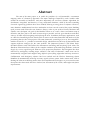
The iRobot Create is a special version of the popular vacuum cleaner robot called “Roomba”. The
Create is specifically designed for hobbyists and robot enthusiasts who wish to build on an existing
platform instead of starting from scratch. Therefore it no longer contains a vacuum cleaner, but rather
a cargo bay with an interface to the internal hardware. In our former Semester Project, a robotics
framework was successfully realized based on the hardware provided by iRobot. The goal of the
project was to create a self-sustaining robot which manages to navigate and explore its environment
by itself without remote influence. This way it is able to return to a charging station if necessary in
order to "to keep alive". The project focused on the development of software which reads data from
the iRobot's built-in sensors as well as from additional sensors, plans the robot's path based on the
sensor data, and controls the robot's movement along this path. The software foundation required for
these tasks was realized along with an in-depth look at theoretical solutions for the given problems. In
addition, a large part of the theory was implemented and tested in both a partially-simulated
environment as well as a physical hardware environment.
Along with the hardware, the resulting software proved stable and very functional. However, it lacked
in functionality and refinement in the following areas: navigation, tracking, simulation, and
diagnostics. The continued most serious hurdle throughout the project was the localization technique.
This was tackled from a software perspective by first trying to make the robot move in a predictable
fashion (such as along a curve), and then to track its position using the sensory data from the hardware
controller. This proved to be a problem, as the localization over time became very inaccurate.
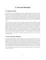
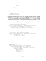
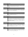
Assembled Robots
Approach
Before attacking the new hurdles presented by the project, the previous work was studied, assessed,
and improved where appropriate. This included the refactoring and cleaning up of code in the
software. In addition, modifications to the hardware were undertaken to make improvements to the
overall design. Most notably, the original docking station was redesigned. The new docking station
was fitted with small incisions in the casing to allow for secondary contact pieces to stick out and
make contact with both the internal batteries and the onboard computer batteries. Next a simulated
environment was realized which enables the emulation of the complete hardware. This was achieved
largely by reverse engineering the behavior of the proprietary hardware. This functionality is essential
for rapid development and testing, as it allows a quick and easy environment for seeing the results of
an algorithm or task. In order to enable third-party applications to make use of the emss framework, a
protocol was defined and implemented. This was realized using UDP over IP technology, and enabled
messages to be remotely sent to and from the framework.
In addition, a new navigation module was implemented to allow an easier environment for which
different tasks can be created in the system. This new module was based on previous work of the emss
project called „System of Weights“ (Krüsi & Grob, 2008). The new navigation module is completely
dynamic and reacts solely on the current perception on the state of the environment at that moment of
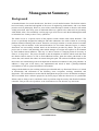
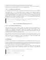
time. Finally, an advanced tracker was implemented which is able to make small corrections in the
localization error when deemed appropriate. To do this, the tracker makes use of a pre-loaded floorplan in order to make correlations between its perceived virtual world and the physical world.
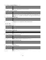
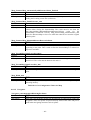
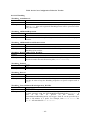
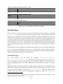
Tracker Performing Automatic Corrections
Results
The resulting emss framework, consisting of a set of “hot-swappable” modules written in C++,
provides an extensible design, which allows a wide array of functionality and supports different
strategies for the same problem. The framework features a full blown multi-threaded software stack
which allows the autonomous controlling and interfacing of the robot. All important modules required
for the navigation, maneuvering, and safe controlling of the robot have been implemented. In
addition, the simulated environment yields an accurate, feature-complete, and flexible workspace for
testing the software.
Safe navigation has been achieved by intelligently avoiding drops, obstacles, and walls by constantly
generating and updating the various supporting data structures. Furthermore, small areas can be
autonomously navigated and mapped using different space-filling algorithms and map structures.
Other routine tasks, such as docking the robot on its docking station, have been implemented and
tested. Collaboration with third-party software has been realized with the Wireless Positioning System
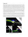
PointZero by automatically collecting the necessary signal reference points, called fingerprints. A rich
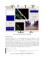
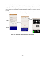
graphical user interface is provided by the framework, allowing user interaction with all the different
modules within.
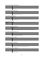
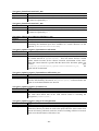
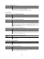
Interface Application with Multiple Viewports and Views
Table of Contents
1 Introduction ..................................................................................................................................... 1 2 Project Definition............................................................................................................................. 3 3 2.1 Task ......................................................................................................................................... 3 2.2 Details ..................................................................................................................................... 3 2.3 Conditions, Infrastructure, Deadlines und Assessment........................................................... 4 Current Situation.............................................................................................................................. 5 3.1 Robotics Field ......................................................................................................................... 5 3.2 Previous Development ............................................................................................................ 5 3.2.1 Hardware ............................................................................................................................. 6 3.2.2 Software .............................................................................................................................. 6 3.2.3 Results and Problems .......................................................................................................... 6 4 Strategy ............................................................................................................................................ 9 4.1 Objective ................................................................................................................................. 9 4.1.1 Concrete Goal ..................................................................................................................... 9 4.1.2 Pre-Requisites ..................................................................................................................... 9 4.1.3 Test Environment ................................................................................................................ 9 4.2 Requirements Specification .................................................................................................. 10 4.2.1 Requirements .................................................................................................................... 10 4.2.2 Use Case............................................................................................................................ 11 4.3 Approach ............................................................................................................................... 12 4.3.1 Milestones ......................................................................................................................... 13 5 6 Hardware ....................................................................................................................................... 15 5.1 iRobot Create ........................................................................................................................ 15 5.2 Vision .................................................................................................................................... 16 5.3 Interface ................................................................................................................................ 16 5.4 Modifications ........................................................................................................................ 17 5.5 Improvements ....................................................................................................................... 17 Software ......................................................................................................................................... 19 6.1 Analysis & Design ................................................................................................................ 19 6.2 Environment .......................................................................................................................... 22 6.3 Implementation ..................................................................................................................... 23 6.3.1 Core ................................................................................................................................... 23 6.3.2 COIL ................................................................................................................................. 25 6.3.3 Controller .......................................................................................................................... 27 6.3.4 Tracker .............................................................................................................................. 29 6.3.5 Map ................................................................................................................................... 39 6.3.6 Navigation ......................................................................................................................... 45 6.3.7 Task ................................................................................................................................... 56 6.3.8 Remote Interface ............................................................................................................... 64 6.3.9 Watchdog .......................................................................................................................... 68 7 6.3.10 Library........................................................................................................................... 69 6.3.11 GUI ............................................................................................................................... 70 6.3.12 Unit Tests ...................................................................................................................... 71 Results ........................................................................................................................................... 75 7.1 Safe-Navigation within a Simple Room ............................................................................... 75 7.1.1 Measurements ................................................................................................................... 75 7.1.2 Evaluation ......................................................................................................................... 78 7.2 Basic Environment Mapping Skills ...................................................................................... 78 7.2.1 Measurements ................................................................................................................... 78 7.2.2 Evaluation ......................................................................................................................... 79 7.3 Basic Localization using Different Data-Sources and Hardware.......................................... 80 7.3.1 Measurements ................................................................................................................... 80 7.3.2 Evaluation ......................................................................................................................... 81 7.4 Protocol for Third-Party Applications .................................................................................. 81 7.5 Assembly of Additional Units............................................................................................... 81 7.6 Additional and Optional Features ......................................................................................... 81 7.6.1 Self-Charging Algorithm .................................................................................................. 81 7.6.2 Self-Healing Tracker ......................................................................................................... 83 7.6.3 Publishing of the Project to Robotics Community ............................................................ 84 7.7 Qualitative Achievements ..................................................................................................... 85 7.7.1 Software Stability.............................................................................................................. 85 7.7.2 Cross-Platform Support..................................................................................................... 85 8 Further Developments ................................................................................................................... 87 8.1 Design Improvements ........................................................................................................... 87 8.1.1 Hardware ........................................................................................................................... 87 8.2 Implementation Enhancements ............................................................................................. 89 8.2.1 Improvements to Current Implementations ...................................................................... 89 8.2.2 Other Enhancements ......................................................................................................... 89 9 Project Management ...................................................................................................................... 91 9.1 Prototypes ............................................................................................................................. 91 9.1.1 Prototype I ......................................................................................................................... 91 9.1.2 Prototype II ....................................................................................................................... 91 9.2 Releases................................................................................................................................. 91 9.3 Project Organization ............................................................................................................. 91 9.3.1 Project Members ............................................................................................................... 92 9.3.2 Weekly Meetings .............................................................................................................. 92 9.3.3 Code Versioning ............................................................................................................... 92 9.3.4 Code Comments ................................................................................................................ 92 9.3.5 Infrastructure ..................................................................................................................... 92 9.4 Risk Management ................................................................................................................. 93 9.5 Timetable .............................................................................................................................. 94 9.5.1 Inception ........................................................................................................................... 94 9.5.2 Implementation ................................................................................................................. 94 9.5.3 Hardware ........................................................................................................................... 96 9.5.4 Project Management ......................................................................................................... 96 9.6 Comparison of Projected and Actual Time ........................................................................... 97 9.7 Metrics .................................................................................................................................. 98 9.8 Personal Report ..................................................................................................................... 99 9.8.1 Daniel Krüsi ...................................................................................................................... 99 9.8.2 David Grob........................................................................................................................ 99 9.9 10 Thanks ................................................................................................................................... 99 Software Documentation......................................................................................................... 101 10.1 Installation........................................................................................................................... 101 10.1.1 Linux and OS X .......................................................................................................... 101 10.1.2 Windows ..................................................................................................................... 101 10.2 Build Instructions ................................................................................................................ 102 10.2.1 Prerequisites ................................................................................................................ 102 10.2.1.1 General .................................................................................................................... 102 10.2.1.2 OS Specifics ............................................................................................................ 102 10.2.1.2.2 OS X........................................................................................................................ 102 10.2.1.2.3 Windows ................................................................................................................. 103 10.2.2 Environment ................................................................................................................ 103 10.2.3 Building....................................................................................................................... 103 10.2.3.2 10.2.4 Manual Build........................................................................................................... 104 Output ......................................................................................................................... 104 10.2.5 Debug Builds .............................................................................................................. 104 10.2.6 Example Script for Fresh Ubuntu Installation ............................................................ 104 10.3 Core ..................................................................................................................................... 105 10.3.1 Linking Against the Core Library ............................................................................... 105 10.3.2 Example Application................................................................................................... 106 10.3.3 Configuration .............................................................................................................. 109 10.4 Interface .............................................................................................................................. 131 10.4.1 First Usage .................................................................................................................. 131 10.4.2 Graphical User Interface ............................................................................................. 132 10.4.3 Configuration .............................................................................................................. 142 10.5 FingerprintCollector ............................................................................................................ 144 10.5.1 Graphical User Interface ............................................................................................. 144 10.5.2 Fingerprinting Guide ................................................................................................... 149 10.5.3 Configuration .............................................................................................................. 154 10.6 Scripts ................................................................................................................................. 157 10.6.1 Initialization ................................................................................................................ 157 10.6.2 Setup ........................................................................................................................... 157 10.6.3 Script Settings ............................................................................................................. 157 10.6.4 Environment ................................................................................................................ 158 10.6.5 Creation ....................................................................................................................... 158 10.6.6 Updating Components................................................................................................. 160 10.6.7 Building Components ................................................................................................. 160 10.6.8 Running Applications ................................................................................................. 161 10.6.9 Cleaning Applications ................................................................................................. 161 10.6.10 Packaging .................................................................................................................... 162 11 Appendix ................................................................................................................................. 163 11.1 Glossary .............................................................................................................................. 163 11.2 List of Figures ..................................................................................................................... 166 11.3 List of Tables ...................................................................................................................... 168 11.4 List of Code......................................................................................................................... 169 11.5 Configuration Files ............................................................................................................. 170 11.5.1 File Format .................................................................................................................. 170 11.5.2 Value Types ................................................................................................................ 170 11.5.3 Patch Files ................................................................................................................... 170 11.6 Eclipse Tutorial ................................................................................................................... 171 11.7 List of Videos ...................................................................................................................... 173 11.7.1 Software ...................................................................................................................... 173 11.7.2 Hardware ..................................................................................................................... 174 11.8 References ........................................................................................................................... 178 1 Introduction
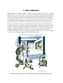
What happened to the robotic revolution? Looking back at old technology and mechanics magazines
from the 1950's, one cannot help but muse at the wild expectations people had regarding the future of
robots. Often portrayed was a bizarre mix of people and machines, living together in a society with
the robot as man's new best friend. Some went to the extent to predict a new race of slaves which
would serve mankind by the 1960’s – as did the 1957 Mechanix Illustrated article You’ll own Slaves
by 1965 (Binder, 1957). The predictions from last century are far from reality. Not only has the
progression of the robot been much slower than expected, traversing a very subtle path, but also its
role in society has been completely redefined from the original conceptions. Instead of serving us
breakfast in the morning, cleaning our living space during the day, and taking our hat and coat from
us when we return in the evening, as depicted in the 1940 film Leave It To Roll-Oh (Handy, 1940),
robots have found their birthplace in the factory. There they toil away all day, and sometimes night,
performing mundane routine tasks over and over. Looking at such a machine, with its precise
movements and repetitive activities, its hard edges and vacuous appearance; it has little resemblance
of ourselves. Is not the robot supposed to be mankind’s birth-child?
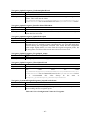
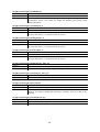
Figure 1-1: Illustration in “You’ll own Slaves by 1965”, Mechanix Illustrated, 1957
-1-
The robotic revolution has not yet undergone in the scale and realm so many thought it would. What
then has kept it? Does the robot just need more time to develop and grow, or is our concept of the
robot fundamentally flawed? A long standing problem in the field of robotics is the perception of the
environment. To us humans, this is a trivial task. We see, hear, and touch our environment around us,
combining these senses to form a somewhat indescribable organic perception of the world (Thorpe,
Clatz, Duggins, Gowdy, MacLachlan, & Ryan, 2001). It is here, at one of the most essential parts of
our defining quality, where the robot has stumbled. The ability to perceive the environment and
comprehend its implications is the first step in actively being a part of it. Only then can a robot take
it’s prematurely crowned role of being mankind’s helper. For thousands of years we have tried to
understand our perceptions, starting with primitive cave drawings and slowly mastering perception
with realistic paintings. However, teaching robots to understand perception has proven very difficult,
even though a robot can easily imitate its environment through the form of radar, sonar, lidar, or
visual images.
After forty years of dedicated efforts on a global scale, robots still have trouble recognizing our face,
they move carefully through our world with a slow pace, and are shy to interact. They just barely have
learned how to walk (Webb, 2001). In many ways, the robot is still a toddler – unable but eager to
explore the world. However, they are growing faster and faster. Each year we are introduced to new
robots that are superior in perception and mobility. Each year new robots join our daily lives in some
fashion or another. Our question remains; when will we be able to christen this century as the Century
of Robotics?
-2-
2 Project Definition
2.1 Task
The concrete goal is to create a basic environment map of obstacles and floor plan to the most
accurate degree possible with the given hardware and data-sources while safely navigating and
exploring the area, allowing third-party applications (such as a WPS) to use the localization data for
their own purposes. Data Sources for localization are include feedback from wheel servos, emulated
movement through space, infra-red sensor and a pre-rendered floor plan of room structures without
obstacles (hallways, rooms, doors, stairs).
The following subtasks are defined:
1.
2.
3.
4.
5.
Safe-navigation within a simple room
Basic environment mapping skills
Basic localization using different data-sources and hardware
Protocol for third-party application tasks
Assembly of additional units
Delivery documents:
1. Installation Guide, if relevant.
2. Complete compiler-ready source code, including program documentation as well as
download-ready zip file with executable binaries.
3. Technical Report and Software-Engineering Documentation, including High-Level
Programmer Documentation.
4. Additional documents according to requirements of the Department of Computer Science.
2.2 Details
1. Pre-requisites:
a. The physical environment must contain only static obstacles. Moving objects will not
be distinguished from still obstacles on the environment map, however the robot will
attempt to avoid such collisions if possible.
b. Obstacles within the physical environment must portray a certain degree of simplicity
in structure. Complex and intricate structures, such as many chair-legs, cables and
wiring, et cetera should not be present or blocked off.
c. The physical environment must be a closed off region. Doors to other areas must be
closed.
d. The test environment consists of the second-floor of building 6 at HSR including
hallways, stair-drops, doorways, corners, and some large obstacles. A live
demonstration will be given of the robot's functionality in such a test environment.
2. Agile development will be practiced, and where appropriate with Unit-Tests. Value is placed
on well-tested software with easy installation.
3. A User-Manual is only required in justified cases.
-3-
4. For a successful project completion, 12 ECTS points, requiring at least 360 work hours-perperson, will be awarded.
2.3 Conditions, Infrastructure, Deadlines und Assessment
1. Conditions Hardware/OS:
a. iRobot Create Hardware
b. x86 Computer
c. OS: Windows / Linux
2. Software:
a. GNU C / C++
b. Qt 4.5
c. Eclipse IDE
d. GNU GDB
3. Deadlines und Assessment: According to requirements at www.i.hsr.ch.
-4-
3 Current Situation
3.1 Robotics Field
A household name for several decades now, the robot is a well studied creature. The field of robotics
has been keenly researched and applied in the areas of engineering, mathematics, and even distant
practices such as philosophy. Mobile robots, those which are movable and disjoint from their
environment, have been especially studied by both the research community and hobbyists. There
remain few untouched topics revolving around the problematics of such robots. However, most of the
researched topics related to robotics still remain widely unresolved. The community is still trying to
get off its feet to reach the breakthroughs needed to launch the next generation of robots and artificial
beings.
The iRobot Create is a special version of the popular vacuum cleaner robot called Roomba. The
Create is specifically designed for hobbyists and robot enthusiasts who wish to build on an existing
platform instead of starting from scratch. Therefore it no longer contains a vacuum cleaner, but rather
a cargo bay with an interface to the internal hardware. A small niche of iRobot Create hobbyists have
strapped a full-blown laptop computer to the Create (Jonathan, Jonathan, Arvind, Omair, &
Sukhatme, 2008), however, not many of these projects have been developed to a mature state.
Because of the relatively young age of the Create product, there is little code available to kick start
interested enthusiasts, hobbyists, or researchers with their project. The same applies for design
concepts, where the literature revolving around iRobot Create projects widely varies in their opinions
of design advantages and disadvantages (Kostandov, et al., Robot Gaming and Learning using
Augmented Reality, 2007) (Martinez, Haverinen, & Roning, 2008) and does not provide clearly
extractable strategies.
3.2 Previous Development
In our former Semester Project, a robotics framework was successfully realized. Based on the above
mentioned ready-made platform provided by iRobot, the goal of the project was to create a selfsustaining robot which manages to navigate and explore its environment by itself without remote
influence. This way it is able to return to a charging station if necessary in order to "keep alive". The
project focused on the development of software which reads data from the iRobot's built-in sensors as
well as from additional sensors, plans the robot's path based on the sensor data, and controls the
robot's movement along this path. The software foundation required for these tasks was realized along
with an in-depth look at theoretical solutions for the given problems. In addition, a large part of the
theory was implemented and tested in both a partially-simulated environment as well as a physical
hardware environment.
-5-
3.2.1 Hardware
Figure 3-1: Original Design Concept
Based on a concept designed with a CAD program, the different components necessary were
purchased and assembled. The final assembly almost realized the original design except for the
auxiliary tower which was omitted. The mobile hardware of emss robot consisted of the ready-made
iRobot Create platform and a 12-inch i386 laptop computer. The immobile hardware consisted of a
modified docking station which allows for the charging of both the wheel drive batteries as well as the
laptop batteries.
3.2.2 Software
The underlying groundwork for the emss framework was implemented. This included a multithreaded system in which different modules1 interacted with each other to perform navigational tasks.
A large effort was put in developing theoretical solutions which could be applied to problems, or
hurdles, within the framework, such as navigation by splines. A cache of utility classes, such as
different mathematical structures, was implemented into the form of a powerful robotics library. This
library extended to provide a set of GUI widgets which provided a useful interface to the software.
3.2.3 Results and Problems
Throughout the project the assembled robot proved robust and very functional. Complex movement
through space was realized using the onboard controller. In addition to the robot itself, a charging
station was modified to allow the charging of both the drive batteries and the laptop computer.
However, the construction presented some problems. The charging station is quite a steep climb to
dock2, which caused trouble for the robot to dock at full payload. Additionally, the added contact
points for the computer power lines were not very sturdy, and after several docks they tended to
loosen and the contact quality was degraded.
1
2
At that time, modules where actually called components.
About 10%.
-6-
The resulting software proved stable and very functional. However, it lacked in functionality and
refinement in the following areas: navigation, tracking, simulation, and diagnostics. The continued
most serious hurdle throughout the project was the localization technique. This was tackled from a
software perspective by first trying to make the robot move in a predictable fashion (such as along a
curve), and then to track its position using the sensory data from the hardware controller. This proved
to be a problem, as the localization over time become very inaccurate due to the vague information
the hardware provided.
-7-
-8-
4 Strategy
4.1 Objective
4.1.1 Concrete Goal
The concrete goal of the emss project is for the robot to perform a simple mapping of the environment
and its contained obstacles and floor plan to the most accurate degree possible. This must be
accomplished with the given hardware and data-sources. The robot should be able to navigate safely,
exploring its unknown environment. In addition, third-party applications, such as a Wireless Position
System, must be able to use the localization data for their own purposes.
To realize such a goal, the maneuvering and localization (tracking) of the robot must be realized in a
fashion which suites the needs of both the internal processes of the robot, but also those of the
external third-party applications. This means an implementation must consider the effects it has on
other aspects of the project, so that in the end they can all come together to perform the specific task.
4.1.2 Pre-Requisites
In order to reduce the complexity implied by the above stated goal, some pre-requisites and
restrictions have been defined.
First, the physical environment must not contain any dynamic obstacles, such as moving people. This
restriction exists because of the additional complexity required to distinguish between static obstacles
and dynamic obstacles. Thus Moving objects will not be distinguished from static obstacles on the
environment map, however the robot will attempt to avoid such collisions if possible. Furthermore,
Obstacles within the physical environment must portray a certain degree of simplicity in structure.
Complex and intricate structures, such as many chair-legs, cables and wiring, et cetera, should not be
present or be blocked off.
Finally, the physical environment must be a closed off region. Doors to other areas must be closed.
Environments that feature entrances to further regions are undesirable because they not only
significantly increase the complexity of the room structure, but also create a tangible risk of trapping
the robot in one of these sub-rooms.
4.1.3 Test Environment
The test environment consists of, but not exclusively, the second-floor of building 6 at the University
of Applied Sciences Rapperswil. This room provides hallways, stair-drops, doorways, corners, and
some large obstacles. Another test environment is the use of cardboard-boxes to form different
simple-shaped rooms which have a smaller scale.
-9-
4.2 Requirements Specification
4.2.1 Requirements
The following requirements have been carefully evaluated and chosen to accompany the emss project.
They are based on previous experience with the hardware and the needs presented by the project goal.
4.2.1.1
Safe-Navigation within a Simple Room
First-things-first, it is important to consider the robots safety throughout its operation. It must be able
to navigate in a simple room safely, meaning that it typically avoids obstacles it can see and almost
certainly avoids from causing any serious damage, such as driving down stairs or a drop. When the
robot detects such an obstacle, it should be able to assess the situation and appropriately react to it.
4.2.1.2
Basic Environment Mapping Skills
When the robot is placed in an unknown environment, it should be able to navigate and build up the
basic structure of the room based on the sensory data. When the entire structure has been determined,
the robot should then cover the rest of the unknown room to create a map of the environment and the
obstacles contained within.
4.2.1.3
Basic Localization using Different Data-Sources and Hardware
Based on the different data sources (feedback from servos, infra-red sensors, and possible the floorplan of the environment), the software should be able to determine its current position relative to the
starting position at any time.
4.2.1.4
Protocol for Third-Party Application Tasks
Third-Party software should be able to utilize the emss framework for it’s own purposes. For this
reason a protocol must be defined for which positioning data can be retrieved remotely.
4.2.1.5
Assembly of Additional Units
A second-generation robot shall be constructed based on the design of the original hardware. This
includes the modifications required on both the hardware chassis as well as the docking station, along
with the mounting of the laptop unit.
4.2.1.6
Additional and Optional Features
The following requirements are optional and may be implemented if feasable.
Self-Charging Algorithm
The robot shall be able to detect the docking station and autonomously dock itself on it. This must be
achieved using the built-in infra-red signals provided by the docking station.
Self-Healing Tracker
Where the localization has become corrupt or inaccurate, the self-healing tracker shall detect these
errors and correct them, providing more accurate information about the robots whereabouts.
- 10 -
Publishing of the Project to the Robotics Community
The emss project is to be published as an open source project. People who wish to use the software,
make modifications, and redistribute it, must be supported in doing so. To enable this, the appropriate
license must be applied to the source code and made available on the internet.
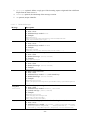
4.2.2 Use Case
The following use cases have been defined to accompany the requirements.
UC1: Safe Navigation
Goal
Preconditions
Annotation
Standard Procedure
Robot must safely navigate through an unknown environment without
touching the wall or falling down a sudden drop.
Batteries are fully charged.
This use case takes effect with all other use cases.
1. User places robot in an unknown environment.
2. User starts robot, it will drive randomly around.
3. Robot avoids collisions and drops.
4. Task is finished when user stops it.
Table 4-1: UC1 Safe Navigation
UC2: WallFollower
Goal
Preconditions
Standard Procedure
Robot searches wall and follows it until it reaches the starting point
again.
UC1: Safe Navigation is implemented.
Room is closed (no open doors).
Room features flat and smooth wall surfaces.
1. User places robot in an unknown environment.
2. User starts robot with the wall follower command.
3. Robot searches for a wall.
4. Task is finished when the whole structure of the room is known
and the robot reaches its start position.
Table 4-2: UC2 WallFollower
UC3: Exploration
Goal
Preconditions
Standard Procedure
Robot explores an unknown environment, fully covering the unexplored
surface.
UC1: Safe Navigation is implemented.
UC2: WallFollower is implemented.
1. User places robot in an unknown environment.
2. User starts robot.
3. Robot maps the structure of the room.
4. Robot explores the whole room, until each area has been
covered.
5. Task finishes when the entire environment is known.
Table 4-3: UC3 Exploration
- 11 -
UC4: Fingerprinting
Goal
Preconditions
Standard Procedure
Alternate Procedure
Automatically collect wireless signal fingerprints with current
positioning data.
UC1: Safe Navigation is implemented.
UC2: WallFollower is implemented.
UC3: Exploration is implemented.
Wireless Positioning Software (PointZero) is running.
Standard procedure if a map of the actual room is available:
1. User starts GUI and loads actual Map and positions the robot on
the map.
2. User sets path (navigation points) for which the robot must
drive.
3. Third-party software connects to emss and starts the
fingerprinting task with the desired settings.
4. Robot drives along the navigation points and stops at each
defined interval to gather a fingerprint.
5. Task is finished when robot reaches the last point on his path.
If no actual map of the current room is available, this alternate
procedure will be processed:
1. User starts GUI manually enters the actual GPS coordinates of
the robot.
6. Third-party software connects to emss and starts the
fingerprinting task with the desired settings.
2. Robot explores the unknown environment and stops after each
defined interval to gather a fingerprint.
3. Task is finished when the whole area is explored.
Table 4-4: UC4 Fingerprinting
4.3 Approach
Before attacking the new hurdles presented by the project, first the previous work is to be studied and
improved where appropriate. This includes the refactoring and cleaning up of code in the software. In
addition, modifications to the hardware will be undertaken to make improvements. The next most
important step is to fully implement a simulated environment for which testing can be done in. This
will greatly reduce the testing time required when developing new algorithms.
Next the navigation module in the software will be extended to allow an easier environment for which
different tasks can be created in the system. This new module will be based on previous work of the
emss project called „System of Weights“ (Krüsi & Grob, 2008) where the implementation will follow
the described theory.
To be able to let third-party software make use of the emss framework, a protocol will be defined and
implemented. This will be realized either with UDP or TCP technology, and will enable messages to
be remotely sent to and from the robot, as well as locally between the framework and other software.
In order to safely navigate through a room, the implemented System of Weights will be used. This
system will have the advantage of allowing different weights to be flexibly defined and configured
which best suite the task or environment. Furthermore, the individual weights will be implemented in
such a fashion that they are most disjoint from each other, providing a flexible system.
- 12 -
An important part of the framework is the localization of the robot. It will be attempted to implement
improved trackers which perform localization based on different input sources. Some might even
combine the different sources for the best judgment. In addition, if the information about the
environment is available, such as the floor-plan, it will be attempted to implement a tracker that can
detect features it sees with its bare sensors (infra-red) and map them to the features described by the
floor-plan. The difference can then be used to calculate the error and perform better localization.
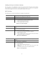
4.3.1 Milestones
Our approach has lead us to many different tasks and goals. These are defined by the following
milestones:
4.3.1.1
1.
2.
3.
4.
4.3.1.2
1.
2.
3.
4.
4.3.1.3
Milestone 1: Week 3
Preliminary work
Implementation of simulated environment
Implementation of System of Weights
Realization of the Remote Protocol
Milestone 2: Week 6
Completion of Prototype I
Safe navigation within a closed, simple room
Implementation of basic environment mapping functions
Release of emss framework v1.1
Milestone 3: Week 9
1. Completion of Prototype II
2. Realization of localization using different data sources
3. Release of emss framework v1.2
4.3.1.4
Milestone 4: Week 12
1. Successful completion of test scenario
4.3.1.5
Milestone 5: Week 14
1. Code-freeze
4.3.1.6
Milestone 6: Week 16
1. Completion of the project and documentation
2. Delivery of all related work, writing, code and hardware
3. Release of emss framework v1.3
- 13 -
- 14 -
5 Hardware
The emss hardware is a simple set of ready-made components, deliberately chosen to avoid many of
the tedious electrical engineering problems presented in the field of robotics. All the components are
plug-and-play and off-the-shelf available as consumer electronics. This chapter gives a short overview
of the hardware schematics which make up the emss robot. A deeper, more detailed look at the
hardware can be found in our previous writings (Krüsi & Grob, 2008).
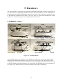
5.1 iRobot Create
Figure 5-1: Assembled Robot
The original decision to use the iRobot Create platform as the basis for our robot was natural. Many
hobbyists and enthusiasts had already used the Create for various projects. Its robust form and easy
assembly proves it to be very attractive. Furthermore, the size and shape of the platform suits our need
to mount a computer and other peripheries very well. Finally, the affordable total cost of ownership of
the iRobot Create platform allows us to build a full blown robot with a small budget.
- 15 -
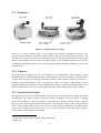
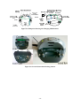
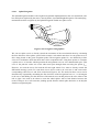
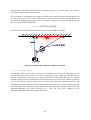
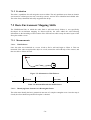
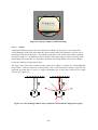
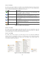
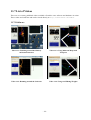
5.2 Vision
In short, the emss robot is very blind. Because of the limited budget, expensive laser range sensors or
lidars could not be purchased. For navigation, the robot uses a single infra-red sensor (80cm range)
which is pointed forwards. In some cases, such as when the robot is following a wall, a short range
infra-red sensor (10cm) can be used which is pointed directly to the right. Figure 5-2 illustrates these
two sensors. The VGA camera which is mounted to the laptop is not used for navigational purposes as
it is outside the scope of our project.
Figure 5-2: Robot Infra-Red Sensors
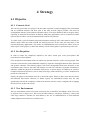
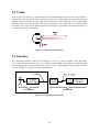
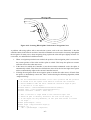
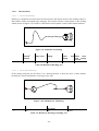
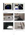
5.3 Interface
The controlling computer connects to the iRobot Create over a serial connection using the iRobot
Create Open Interface protocol. The emss software is responsible for translating all controller data
into the appropriate bit-level packets for the Open Interface. What happens after the Open Interface
receives the packet is largely a black box and unknown.
Figure 5-3: Controlling of the Robot
- 16 -
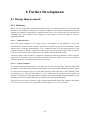
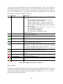
5.4 Modifications
The most important modifications to the iRobot Create hardware are the computer contact points for
the docking station3 along with the necessary cabling (shown in Figure 5-5). These are used in
addition to the built-in contact points for charging of the iRobot Create batteries along with the
computer batteries. Both sets of contact points expose 12V power supply lines which can connect by
physical contact to their peers located at the base station (also shown in Figure 5-5). This mechanism
allows the emss robot to find the docking station using the top-mounted infra-red receiver (described
in detail in Section 6.3.6.3.7) and mount itself on top of the charging station, creating connections
between all sets of contact points, and ultimately recharging its batteries.
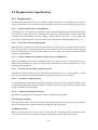
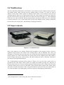
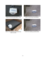
5.5 Improvements
Figure 5-4: Assembled Robots
Most of the hardware was already designed and assembled in the Semester Project. However,
significant improvements were made to the docking station, and an additional emss robot was
assembled. As described in our previous work, the construction of docking station presented problems
during repetitive use. After several docks the contact points for the computer power lines tended to
loosen, sharply reducing the contact quality and often breaking the power connection. Therefore a
new design was proposed and realized.
The second-generation docking station (shown in Figure 5-6) uses the same contact pieces as
provided for the robot chassis. These contacts are angled and rounded just right for a flat piece of
metal to glide on top of it. The new docking station has small incisions in the casing to allow for these
secondary contact pieces to stick out and make contact with the laptop contacts. The contact pieces
and neatly screwed to the bottom of the casing and soldered to the power lines. The final product is
very clean and stable, with a high quality contact rate and power throughput for both batteries.
3
The docking station is used to charge the robot’s wheel drive batteries.
- 17 -
Figure 5-5: Blueprint Showing the Charging Modifications
Figure 5-6: Second-Generation Docking Station
- 18 -
6 Software
The emss project touches on the subjects of many fields: mathematics, engineering, hardware, and
finally software. However, the focus is clear: software. From a computer science enthusiast’s point of
view, this is where robotics gets interesting. The software related problems of the emss framework can
be categorized into three domains: communicating with hardware, solving the problems of the given
objectives, and presenting the state of the problem and solution to the user.
Throughout the development of the framework, a significant amount of energy was focused on
maintaining a highly flexible architecture consisting of a set of modules which interact with each
other to achieve a common task. Every added module and component has undergone a rigorous
thought process to justify its need and make sure it is absolutely necessary.
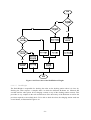
6.1 Analysis & Design
User
WPS
emss
Robot
Place robot
Position Robot and set Path
Start fingerprinting
Subscribe
Start task
Loop until last
navigation point is
reached
Interval
reached
Stop Robot
Robot’s position
Collect
fingerprint
Stop time
elapsed
Start Robot
Task Finished
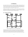
Figure 6-1: Fingerprinting Use Case System Sequence Diagram
Throughout the analysis of the software, the existing emss framework (Krüsi & Grob, 2008) was
examined along with the new use cases. Upon examination, it was clear that the existing Navigation
module would have to be redesigned to better suit the needs of the next generation of the framework.
In addition, it was also clear that new modules would be added. The original framework, however,
was built with this in mind, allowing a clear notion on how the new design would fit with the existing.
- 19 -
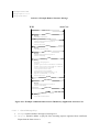
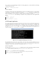
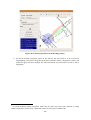
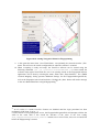
Figure 6-1 shows the most interesting use case (UC4, Section 4.2.2) as a system sequence diagram. It
illustrates how the individual players must work together in order to collect fingerprints. The use case
requires user interaction with both the third-party WPS software and emss framework. The interaction
between WPS and emss is achieved without any further user interaction.
The emss framework should have the functionality to control the robot, track its position and perform
localization, as well as execute the navigation. These modules must remain highly flexible and
interchangeable depending on the underlying hardware and the requested use and purpose of that
hardware. This allows the creation of tasks for a wide variety of topics without necessarily knowing
the exact details of the underlying modules used. One can set navigation points and make the robot
navigate through the resulting path without having to decide what kind of splines to create for the
trajectory or how to avoid unexpected obstacles.
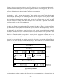
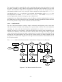
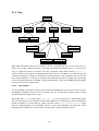
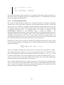
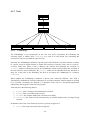
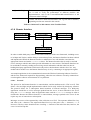
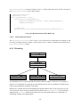
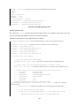
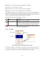
To enable such an environment, the following software stack, shown in Figure 6-2, has been designed.
It shows the different layers and how they stack on top of each other to form the overall architecture
of the framework. The very bottom represents the physical hardware which has proprietary software.
This is not a part of the emss framework, but the framework makes use of this layer. Directly on top
of the hardware lies the Hardware Abstraction Layer (HAL), which communicates directly with the
hardware’s interfaces but exposes a much more simple and unified interface to the layers above. This
is the first layer in the emss Core – the central software of the framework. Sending commands to the
HAL is the Controller, which is responsible for ensuring that the appropriate commands are sent to
and from the hardware (through the HAL) at the right time. In the middle lies the Task Manager and
its Tasks, which execute the different jobs which essentially control the robots actions. The top-most
layer of the Core includes all the modules required for efficiently executing the different jobs (or
Tasks). On top of the Core layers are the Interface layers, which enable the user to interact with the
framework and present the current state of the different layers.
Figure 6-2: Layer Model
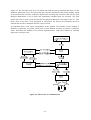
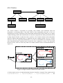
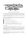
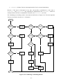
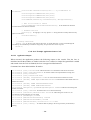
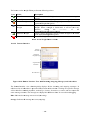
All these modules that make up the different software layers communicate with each other and
exchange data to perform a common task. The basic lines of communications are illustrated below in
- 20 -
Figure 6-3. The Controller runs in its own thread and reads the sensory data from the robot over the
Hardware Abstraction Layer. The data is then processed and forwarded to the Tracker module, which
in turn performs the necessary localization based on the incoming data. From the other side, the Task
Manager administrates a list of Tasks and sequentially schedules them for execution. The Task
defines the action it wants to take and asks the Navigation module how it can achieve this (i.e. „how
must I drive to do this?“). The Navigation in turn queries the Tracker for information about its
whereabouts in order to determine the best course of action.
An important factor is the intern changeability of the modules. The interface of each module is
defined as generically as possible, taking into account different scenarios and wishes of different
Tasks. This allows the module to have several implementations, each with a different or extended
approach in solving its task.
Figure 6-3: Basic Lines of Communication
- 21 -
6.2 Environment
Because of the natural progression of software languages and operating systems, the choice and
understanding of the environment of software has become increasingly important. Working with
microcontrollers in the field of robotics, we chose the programming language of C++, which is well
proven in the industry as a robust middle level language4. C++ is both a highly advanced and efficient
language, and if used correctly results in very stable and robust applications.
C++ by itself does not offer any support in creating cross-platform graphical user interfaces, which is
why we use the Qt framework from Qt Software (formerly Trolltech) to assist us. We are very proud
to be able to offer a software framework in which every component, including modules such as serial
communications, cross-compile on Windows, Linux, and OS X. All software components are written
in C++ and are fully compatible with any of the GNU 4.x compilers. Additionally, we have made use
of software libraries. The Core modules of the emss software are all packaged into a single library,
which in turn is linked to by any of the user interfaces.
The use of Qt Signals and Slots5 has been used heavily throughout the framework. Signals and slots
are used for the communication between objects. They are similar to callbacks using pointer
functions, but have the advantage that they are type-safe, meaning the signature of a signal must
match the signature of the receiving slot. One might ask how this is possible using C++: Qt uses a
meta-object compiler (MOC) to achieve the signal and slot functionality by creating meta-objects for
classes. The meta-object contains the names of all the signal and slot members, as well as pointers to
these methods. The MOC parses the class declaration in a C++ file and generates C++ code that
initializes the meta-object.
Constants typically have been avoided throughout the implementation for any value that has changed
several times. Such values are defined in a configuration file, which in turn is loaded and cached by
the code which needs it. This allows a much more flexible system, where reconfiguring does not
require a tedious recompilation. In all, there are well over 150 different configuration settings which
are documented in detail in Sections 10.3.3, 10.4.3, and 10.5.3. The amount of configuration settings
portrays the complexity of the software.
Wherever possible and deemed appropriate, C++ features such as class inheritance, operator
overloading, and templates have been made use of. In addition, because of the multi-threaded nature
of the emss framework, thread-safety precautions have been taken wherever necessary through the use
of operating system level locks6.
4
Middle-level languages compromise a combination of high-level features and low-level advantages.
If you are unfamiliar with this design concept, we recommend Qt’s introductory document found on
their website at http://doc.trolltech.com/4.5/signalsandslots.html.
6
In particular, mostly read/write locks have been used.
5
- 22 -
6.3 Implementation
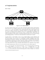
6.3.1 Core
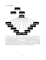
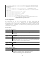
Figure 6-4: Core Domain Model
The software which essentially runs our emss robot is divided into different modules which ultimately
make up the emss Core. Modules within the Core are built separately into the library emssCore
(libemssCore.a). The Core initializes all the required data-layer objects, binds together all the
different Core modules, and makes sure everything is cleaned up. Any application wishing to make
use of the emss framework must instantiate its own Core. Communications with different Core
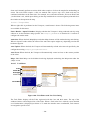
modules are then proceeded over this Core object, mostly via signals and slots. Because the Core
holds responsibility for all the modules, an interfacing application needs not to worry about cleaning
up and managing memory– all it must do is disconnect the Core and delete the Core object.
Up until version 1.0, the modules of the emss Core changed slightly as needs changed for the
framework. However, since version 1.1 the Core modules have remained unchanged as far as design.
The current modules, shown in Figure 6-4, are Watchdog, Controller, TaskManager, Map, COIL,
RemoteInterface, Navigation, and Tracker. These modules all play a significant role in the operation
of controlling the robot and quite accurately reflect the contents of the software stack described in
Section 6.1. Any module within the emss Core must inherit from either CoreObject or CoreThread
class, which describes the two types of modules found within the Core. Furthermore, many modules
have multiple implementations which solve the same problem but with a different approach.
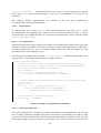
The Core class itself offers some important functionality – the most important being the initialization
and connection methods initMapsAndObjects() and connect(…). In addition, also start() and
stop() methods are provided which help in safely starting and stopping all the different
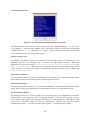
CoreThreads. This resolves the Core into the following states (as shown in Figure 6-5): Initialized,
Connected, Started, Stopped, Destroyed.
- 23 -
Figure 6-5: Core State Diagram
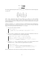
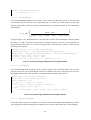
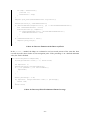
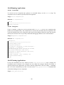
The following code shows how the Core might be initialized, connected, and started. It also
demonstrates how to safely shut it down and cleanup. For more details see Section 10.3.2.
// Create a emss Core with settings specified in emssCore.config
Core *core = new Core();
// Connect the Core with the following configuration and start it:
//
Controller:
EmssController
//
Tracker:
SingleTracker
//
Navigation:
SystemOfWeightsNavigation
//
Serial Port:
/dev/TTYUSB0
//
Safe Mode:
true
//
Emulation:
true
if(core->connect("EmssController", "SingleTracker", "SystemOfWeightsNavigation",
"/dev/TTYUSB0", true, true)) {
core->start();
// The Core is running and ready now...
// Shutdown the Core
core->stop();
core->disconnect();
}
// Cleanup
delete core;
Code 6-1: Core Initialization and Connection Example
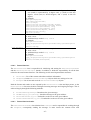
6.3.1.1
Thread-Safety
Any module within the Core must be thread-safe where it has exposed methods, as there are different
interacting threads which run in a connected Core. This is achieved by using system-level locks,
mostly read/write locks. In most cases, a module will contain a private read/write lock for the data it
must guard and perform lock operations around any internal code accessing this data. Always when
possible a differentiation has been made between code which requires only read access and code
which requires write access in order to boost performance.
- 24 -
6.3.1.2
CoreObject
A module in the Core which either does not require any continuous processing or is processed by
another module inherits from the CoreObject class. The CoreObject is a simple interface which only
requires a human-readable type name and a pointer to its Core in order to be constructed. In addition,
when activated, HeapLogger routines are called in order to keep track of which CoreObjects are on
the heap.
6.3.1.3
CoreThread
A module in the Core which requires continuous processing in the fashion of a thread must inherit
from the CoreThread class. Similar to a CoreObject, CoreThread is a simple interface which only
requires a human-readable type name and a pointer to its Core in order to be constructed. In addition a
thread priority may be specified in the constructor. When activated, HeapLogger routines are called in
order to keep track of which CoreThreads are on the heap.
6.3.1.4
CoreFactory
The CoreFactory class serves as the factory for the entire Core. It is responsible for creating the
different modules and their various implementations.
For modules which have multiple
implementations a name must be specified which corresponds to the human-readable type name given
in CoreObject or CoreThread.
All factory methods return pointers to a created object on the heap when successful, and NULL
otherwise. Objects returned by the CoreFactory remain under the responsibility of the callee, meaning
that they must also be cleaned up by the one who called the factory method. However, in most cases
this responsibility can easily be delegated.
The
following
factory
createMovementTracker(…),
methods
are
available:
createCOIL(…),
createNavigation(…),
createTracker(…),
createTaskManager(…),
createController(…), createRemoteInterface(…), createWatchdog(…), createGUIView(…),
and
createTask(…).
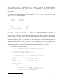
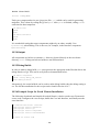
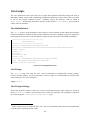
6.3.2 COIL
The C Open Interface Library7, or COIL, was originally implemented by Jesse DeGuire and Nathan
Sprague as a POSIX compliant C wrapper for the iRobot Open Interface. We have created a C++
7
For more information about the original COIL, please visit http://code.google.com/p/libcreateoi.
- 25 -
version of COIL which compiles on Windows, Linux, and OS X. The Core module COIL represents
the Hardware Abstraction Layer, or HAL, in our software stack, and is solely responsible for
communicating directly with the hardware.
COIL opens a serial port and directly communicates with the iRobot Open Interface. All the
functionality defined by the Open Interface has been implemented as easy-to-use methods within the
COIL class. Furthermore, the COIL class includes over a hundred different type-def values which
correspond to the different bytes and bits used by the Open Interface. The two most important parts of
COIL are the sending of wheel drive commands (handled by drive(…), driveDistance(…),
directDrive(…), and turn(…)), and the extraction of sensor information from the stream of data
coming from the hardware (handled by readRawSensor(…) and extractSensorFromData(…)).
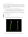
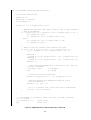
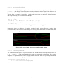
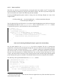
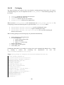
The following example drives the robot along the path of a square and demonstrates the simplicity
which COIL offers when communicating with the hardware:
for(int i = 0; i < 4; i++) {
coil->driveDistance(150,0,1000,1)
coil->turn(150,0,90,1)
}
// Drive 1000 mm straight ahead at 150 mm/s
// Turn 90 degrees at 150 mm/s
Code 6-2: Using COIL to Drive along the Path of a Square
The above code will translate the COIL commands into a complex series of communications over the
serial port with the iRobot hardware. These communications include:
1. Translation and transmission of controller commands on the bit level
2. Listening and translation of incoming sensory data
3. Timing of incoming and outgoing transmissions
6.3.2.1
EmulatedCOIL
The EmulatedCOIL implementation of COIL plays a very important role within the emss framework:
it enables a completely emulated environment of the iRobot Create hardware. This is essential for
rapid development and testing, as it allows a quick and easy environment for seeing the results of an
algorithm or task. All the relevant sensory packets received by the hardware have been implemented
and are available in the EmulatedCOIL class. Because of the thin documentation provided by iRobot
regarding the Open Interface, many of the different sensor packets have been reverse engineered
using comparison and trail-and-error methods. Everything from battery levels to infra-red signals have
been implemented in EmulatedCOIL.
In order to be able to emulate the environment of the robot, the EmulatedCOIL class relies on the
Tracker module and the PhysicalMap. The Tracker module provides the necessary information for the
current position of the robot used when querying the PhysicalMap for the information about the
surrounding environment for sensory data. In addition, timers are used internally for information
returned by methods such as getDistance(), which returns the distance travelled since the last query.
The most notable reverse engineering is the getAngle() method, which returns the change of angle
since the last query. The mathematics for this method is based largely on our previous work (Krüsi &
Grob, 2008) and is similar to the change of angle calculated by the ExpectedMovementTracker in
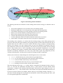
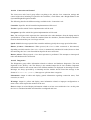
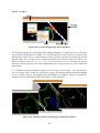
Section 6.3.4.4.2.
- 26 -
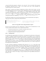
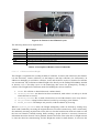
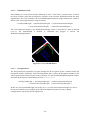
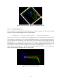
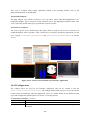
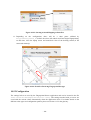
An additional important role of the EmulatedCOIL class is not only to emulate the hardware behavior
as it is desired, but also to emulate the undesired effects and inaccuracy in the hardware. This has
been implemented by allowing EmulatedCOIL to select a specific additional MovementTracker (a
specific localization implementation) within the Tracker module for determining its sensory
information. If the selected MovementTracker has an error calculated into it, which is supported by
MovementTrackers such as the CorrectedFrenetMovementTracker, then the returned sensory data will
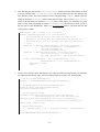
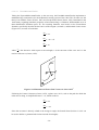
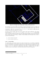
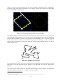
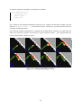
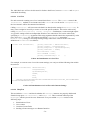
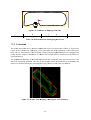
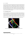
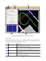
not be accurate in comparison with the Tracker module. This technique is best illustrated by Figure
(blue) and
(yellow) where
is the
6-6. The diagram shows two MovementTrackers
is the MovementTracker used by the
MovementTracker used specifically for EmulatedCOIL and
rest of the Core modules. The two detected collision areas
and
are a result from the
MovementTracker
detecting the white wall, and the arrows indicate the offset for which the
detection was actually registered in the HeatMap which stores information about the environment
such as collision areas and safe areas (red/green spots). As one can quickly see, the configuration in
Figure 6-6 results in a simulated error related to the EmulatedCOIL’s selection of a error-injected
MovementTracker. This is part of the continued effort to provide a robust emulation environment.
Figure 6-6: EmulatedCOIL with Hardware Error Emulation
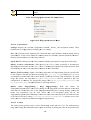
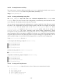
6.3.3 Controller
- 27 -
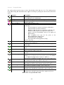
The Controller module is responsible for safely controlling and maneuvering the hardware. It sends
the control commands to COIL which in turn translates and transmits the commands over the serial
interface. The Controller module is also responsible for receiving sensory data and providing it to
other modules within the emss Core, such as the Tracker module and various Maps. The Controller
class inherits from CoreThread and runs in its own thread. Implementations of the Controller class
must implement the methods process() and setWheelSpeed(…). The method emergencyStop()
must be implemented to handle an emergency stop in further detail.
Originally the emss framework contained a series of different Controller implementations, however
these differences have been refactored to the Tasks which originally required these features and now
the Core only contains a single common Controller, the EmssController.
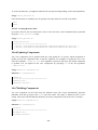
6.3.3.1
EmssController
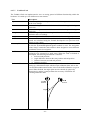
The role of the EmssController is relatively simple: continuously and frequently retrieve sensor data
and send movement commands while making sure to operate safely at all times. The main method for
controlling the robot with the EmssController implementation is via the setWheelSpeed(...)
method. This allows a Core module to set the desired wheel speed which is then transmitted by the
controller to the hardware. If an unsafe movement is detected, such as driving down a drop or against
a wall, the Controller will ignore any further commands until a reversing command is desired which is
deemed safe. The EmssController will never take any counter-action to an unsafe command, it will
just ignore the command. This delegates the resolving of an unsafe situation to other modules such as
the Navigation module.
The process() method of the EmssController is detailed below in Figure 6-7 as a flow chart.
Figure 6-7: The EmssController Flow Chart
- 28 -
6.3.4 Tracker
The Tracker module is responsible for providing other modules with information about the
localization, or positioning data, of the robot. However, this responsibility only goes so far as to
delegating the necessary calculations to the internal MovementTrackers which it then uses to compile
a single resulting position. MovementTrackers are therefore responsible for making calculations based
on input from the Tracker on where the robot’s position is. The Tracker can then use this information
from the different MovementTrackers to determine the best suitable position. Even if a Tracker
chooses to only use a single MovementTracker as its source of information for localization, having
other MovementTrackers registered proves useful for error comparison et cetera. The interaction
between an actor, such as a Task or any other Core module, and the Tracker is demonstrated below in
Figure 6-8.
Figure 6-8: Representation of Interaction with Tracker
A Tracker mostly receives its input information from the Controller via signals. These signals include
and
signalMovedDistance(...), signalChangedAngle(...), signalChangedWheelSpeed(...),
- 29 -
signalObjectDetected(...).
As mentioned earlier, the Tracker is solely responsible for relaying
these signals to its various MovemenTrackers, where the real calculations for localization are
performed.
The following Tracker implementations are available in the emss Core: SingleTracker,
AveragedTracker and SelfCorrectingTracker.
6.3.4.1
SingleTracker
A SingleTracker may contain one or more MovementTrackers but only uses a single
MovementTracker for determining the robots position. The MovementTracker which is used is
specified in the Core configuration file (see 0), and can be changed during runtime with the method
setSelectedMovemenTracker(...).
6.3.4.2
AveragedTracker
Unlike the SingleTracker, the AveragedTracker makes use of multiple MovementTrackers at the same
time. The resulting localization is the mean, or average, of all the MovementTrackers. Additionally,
each MovementTracker may have an assigned weight, which will skew the influence of the
MovementTracker on the resulting average.
The following code segment shows how the calculateTotalAngle() method is implemented for the
AverageTracker, which returns the total change of angle travelled.
double calculateTotalAngle(){
// Find out the total weight. A MovementTracker does not necessarily have
// to have a weight of 1. When the weight is increased the MovementTracker
// will have a higher influence on the result.
int totalWeight = 0;
for(int i = 0; i < movementTrackers->count(); i++){
totalWeight += movementTrackers->at(i)->getWeight();
}
// Iterate through every MovementTracker and add its value times the weight
// to the total
double total = 0;
for (int i = 0; i < movementTrackers->count(); i++){
total += movementTrackers->at(i)->getWeight() *
movementTrackers->at(i)->getTotalAngle();
}
// The end result is the skewed average
return total / totalWeight;
}
Code 6-3: Example AveragedTracker Calculation
6.3.4.3
SelfCorrectingTracker
The SelfCorrectingTracker is an advanced Tracker which inherits from SingleTracker. This Tracker
doesn’t change anything the SingleTracker does, but extends its functionality to be able to make
corrections when deemed applicable. To do this, the SelfCorrectingTracker makes use of the currently
loaded PhysicalMap to map correlations and determine if the overall localization has peered off in
- 30 -
error. If such an error is determined, it is accordingly corrected by adjusting all the
MovementTrackers positions. This Tracker looks to be promising for future work related to
improving the quality, or accuracy, of the robot localization, and is described in larger detail than the
other Trackers.
To realize the SelfCorrectingTracker, the data structure CorrelationTriangle (see Figure 6-9, top)
and SuspectedWall has been defined8:
struct CorrelationTriangle {
Trafo2D
position;
Trafo2D
collision;
Trafo2D
closestWall;
};
struct SuspectedWall {
bool
valid;
CorrelationTriangle
start;
CorrelationTriangle
end;
};
For
every
which the SelfCorrectingTracker receives, a
CorrelationTriangle, is pushed to a log which stores the current robot position, the collision
position, and the closest wall position from the collision location – thus a correlation between the
position, collision, and closest wall. If the log contains enough correlation triangles, all the collision
positions and closest wall positions are checked if they represent similarities to a wall. If so, the
SelfCorrectingTracker makes a correction to the MovementTrackers positions. Because such an
algorithm naturally requires many processing cycles (determining closest wall, creating line
structures, et cetera), a considerable amount of effort has been made to optimize the
SelfCorrectingTracker. The simplified algorithm is described in detail below, step by step.
signalObjectDetected(...)
1. Determine the correlation triangle ct:
// Get current position and corresponding collision point
CorrelationTriangle ct;
ct.position = tracker position
ct.collision = object detected position
// Find closest 'wall' (ct.closestWall) to ct.collision.
// This is done by 'spiraling' out from the center (ct.collision)...
double r = 0;
// The current radius
double rmax = 2000;
// The maximum spiral radius
double a = 0;
// The current angle
double amax = 360;
// The maximum spiral angle
while(r < rmax) {
a = 0;
while(a < amax) {
Trafo2D pos = ct.collision * Trafo2D::rot(a) *
Trafo2D::trans(0, r);
if(pos is a wall on PhysicalMap) {
ct.closestWall = pos;
8
The class Trafo2D is the two-dimensional transformation matrix class in the emss Core library.
- 31 -
break;
}
a++;
}
r++;
}
2. Add ct to our log if the closest wall could be determined:
// Add the ct to the log
correlationLog.append(ct);
3. Determine whether there are two straight lines (see Figure 6-9, bottom left) in the log made
up of n ct.collision’s and n ct.closestWall’s which make up a SuspectedWall structure
wall. First we need to detect the most distant two points in ct.collision in our log. This
but we optimize by first calculating the bounding box, then taking the points
would be
which are on the bounds, and finally finding the most distant of those. The best case is
,
. The worst case can only happen if all points are on a straight
and the worst case is
vertical or horizontal line, which in reality will hardly ever (if ever) be the case..
// Get the bounding box of the ct points
foreach (CorrelationTriangle ct in the last n in correlationLog) {
if(ct.collision.x() > xmax) xmax = ct.collision.x();
else if(ct.collision.x() < xmin) xmin = ct.collision.x();
if(ct.collision.y() > ymax) ymax = ct.collision.y();
else if(ct.collision.y() < ymin) ymin = ct.collision.y();
}
// Get all the ct points which ly on the bounds
foreach (CorrelationTriangle ct in the last n in correlationLog) {
if(
ct.collision.x() == xmin ||
ct.collision.x() == xmax ||
ct.collision.y() == ymin ||
ct.collision.y() == ymax ) {
// Lies on the bounds, add to candidates
candidates.append(ct);
}
}
// Now we have our candidates - find the most distant ct points!
i = candidates.constBegin();
double maxdist = 0;
foreach (CorrelationTriangle cti in the candiates) {
foreach (CorrelationTriangle ctj in the candiates) {
double distij = dist( cti.collision, ctj.collision );
if( distij > maxdist ) {
maxdist = distij;
wall.start = cti;
wall.end = ctj;
}
}
}
- 32 -
4. Now that the two most distant CorrelationTriangle points have been determined, we need
to check if all the other CorrelationTriangle’s in the log fall close to the line between the
most distance points. There are actually two lines. The first being lineWall, which is the line
along the detected closestWall points (from physical map). The second is lineCollision,
which is the line along the detected collision points (from sensor). To determine if a point
falls on a line with a permitted deviation maxLineDeviation, the distance from a point to
the line can be used (Kimberling, 1998):
|
|
,
|
|
where
represents the line and
the point to sample.
wall.valid = true; // Assume it is a valid wall
foreach (CorrelationTriangle ct in correlationLog) {
// Get the distance of this ct point from the line. If the
// distance is too large, then the suspected wall is invalid, as
// the points do not fall on a straight line (what we assume to be
// a wall.
double dw = ( det(wall.end.closestWall - wall.start.closestWall,
wall.start.closestWall - ct.closestWall) ) / (
wall.end.closestWall.x() wall.start.closestWall.x() );
double dc = ( det(wall.end.collision - wall.start.collision,
wall.start.collision - ct.collision) ) / (
wall.end.collision.x() - wall.start.collision.x()
);
if(dw > maxLineDeviation || dw < -maxLineDeviation || dc >
maxLineDeviation || dc < -maxLineDeviation) {
wall.valid = false;
break;
}
}
5. Finally, if the wall has been determined to be valid, the SelfCorrectingTracker can determine
the angle between the two lines, and correct the position (see Figure 6-9, bottom right).
// Get the current transfomration
Trafo2D t = selectedMovementTracker->getTransformation();
// Get the distance to go back and forwards again
double d = dist (wall.end.collision.trans(),
wall.start.collision.trans());
// Get the angle to correct
Vector2D lc(wall.end.collision.x()-wall.start.collision.x(),
wall.end.collision.y()-wall.start.collision.y());
Vector2D lw(wall.end.closestWall.x()-wall.start.closestWall.x(),
wall.end.closestWall.y()-wall.start.closestWall.y());
double alpha = angle(lc,lw);
// Perform the correction
t = t * Trafo2D::trans( 0, -d ) * Trafo2D::rot(alpha) * Trafo2D::trans( 0,
d );
selectedMovementTracker->setTransformation(t);
- 33 -
Figure 6-9: SelfCorrectingTracker in Action
6.3.4.4
Movement Tracker
A MovementTracker is responsible for receiving the Tracker’s messages regarding changes in the
state of the robot and performing localization based on this information. The methods a
MovementTracker implementation must implement are registerMovedDistance(...),
registerChangedAngle(...), and registerChangedWheelSpeed(...). However, not all of these
methods must react in some fashion – technically and mathematically it is sufficient to react solely to
the registerChangedWheelSpeed(...) method.
6.3.4.4.1
RawMovemenTracker
The RawMovementTracker works with the raw sensor data of the robot. This means the Controller
controls via COIL the robot and determines the individual wheel speeds. With every process() of the
Controller the sensor data is queried and passed along to the Tracker and eventually the
- 34 -
RawMovementTracker. Within this sensor data is the change in angle and the distance driven, which
is determined by the onboard-controller of the robot. It is this data which the RawMovementTracker
reacts to and performs its localization via the methods registerChangedAngle(...) and
registerMovedDistance(...).
6.3.4.4.2
ExpectedMovementTracker
The ExpectedMovementTracker is based on our previous work (Krüsi & Grob, 2008) related to the
movement of a differential steering system over time. The aim of the ExpectedMovementTracker is to
perform localization based solely on what one would expect the hardware to do, that is,
mathematically. While the results are very satisfactory, the ExpectedMovementTracker however is
not mathematically sound – it is only an approximation.
The tackled problem here is that the emss robot has a differential steering system with independent
(provided by the method registerChangedWheelSpeed(vl,vr)). Our
wheel velocities and approach is based on the movement of each wheel as arcs of circles, as shown in Figure 6-10. The
radius of these circular trajectories is given by the difference of velocities. With this approach one
immediately assumes
, as when
the radius
∞ and the emulation for
is
trivial. With this model one can formulate the local change in angle as:
where
is the distance travelled by the arbitrarily chosen left wheel (arc length of
is defined as
). The radius
.
Thus the offset of the robot over time
can trivially be calculated using
and
, which is
exactly what the ExpectedMovementTracker does.
Figure 6-10: Robot Moving CCW on Circle Arcs
The precision of the ExpectedMovementTracker decreases as increases because of the way the
transformation is applied. However, as already stated the error remains very low since is always
small in relation to .
- 35 -
6.3.4.4.3
FrenetMovemenTracker
Taking the ExpectedMovementTracker to the next step, the FrenetMovementTracker implements a
mathematically sound tracker for the differential steering system of the robot. This Tracker uses the
theory Jean Frédéric Frenet (Frenet, 1847) and Joseph Alfred Serret (Serret, 1851) formulated in the
19th century regarding kinematic properties of movement along a continuous, differentiable curve in
. The resulting formulas, now known as the Frenet-Serret
three-dimensional Euclidean space
formulas, specifically describe the derivatives of the tangent , normal , and binormal unit vectors
(Figure 6-11) in terms of each other:
where
is the derivative with respect to the arclength,
is the curvature of the curve and
is the
torsion of the curve (Carmo, 1976).
Figure 6-11: Illustration of Frenet Unit Vectors for Curve in R3
Following do Carmo’s literature (Carmo, 1976), a plane curve in
robot moves along, is simplified because
0, which results in:
, such as the path for which the
Since the curvature is directly related to the change in angle, the formula from Section 6.3.4.4.2 can
be used to define (parametrized for time instead of arclength):
- 36 -
2
·
The following differential equation must be solved in order to determine the movement through space
over time in :
·
·
·
·
·
·
·
·
where
and
represent the input vectors for position ( , ), speed ( , ), and acceleration
( , ), and
represents the change in distance. The differential equation can be solved using
common methods such as Euler or Runge-Kutta, which have both been implemented for this purpose
in the Core math library.
Utilizing our templated FrenetT math class, the theory is realized using the steps described below.
Special care has been taken to automatically determine the best value when solving the differential
equation. The following code demonstrates how the FrenetT is used:
1. First the curvature function is defined:
double k (double t) {
// Note that t is not used because of the constant vr and vl
return -( 2.0 / d ) * ( vr - vl ) / ( vr + vl );
}
2. Then the values are initialized for the calculation. Note that the calculations are done on a
local scale (i.e. starting from point 0,0), and then applied globally.
double hcount = 100; // Move to t with h hcount times
double h = (t/1000.0)/hcount; // h value for Runge-Kutta
double phi = Rad(90); // straight ahead along the y-axis
DiffEqVectorD y0 = DiffEqVector<double>(0, 0, Cos(phi)*v, Sin(phi)*v,
Sin(phi)*v, -Cos(phi)*v);
3. Finally the FrenetT class is initialized with a pointer to the curvature function and the
initialization vector y0, which is then used to approximate the new position.
FrenetD frenet(k, y0);
DiffEqVectorD newPosition = frenet.ApproximateDiffEqVector(
FrenetD::ApproximationMethodRungeKutta, t/1000.0, h);
transformation = transformation * Trafo2D::trans(newPosition.x0(),
newPosition.y0()) ;
We have found that an
value of 100 is best suited for performing accurate approximations.
- 37 -
6.3.4.4.4
CorrectedFrenetMovementTracker
The CorrectedFrenetMovemenTracker extends the FrenetMovemenTracker by inserting predefined
error-values in all movements. This Tracker is used to mimic any error which is prevalent in the
hardware. For example, if the hardware always tends to peer right, the
CorrectedFrenetMovemenTracker can be used to create a Tracker which represents this behavior of
the hardware. The Callibration TestMoveTask helps in determining the error values needed by the
CorrectedFrenetMovemenTracker.
The following values modify the behaviors of the CorrectedFrenetMovemenTracker:
1. evl: defines how much percent the left wheel velocity deviates for all incoming movements.
2. evr: defines how much percent the right wheel velocity deviates for all incoming movements.
3. dv: defines the minimum difference required between the left and right wheel speeds.
The dv value is used to mimic hardware which cannot differentiate between very subtle movement
changes. For example, if dv is 4, then the wheel speeds vl=150 and vr=152 will be translated as
vl=151 and vr=151 (average).
if(dv != 0 && abs(left-right) < dv) {
left = (left+right)/2;
right = (left+right)/2;
}
processMovementByTime(t, left + left*evl, right + right*evr);
Code 6-4: Modifications to Wheel Speeds by CorrectedFrenetMovemenTracker
Error
FrenetMovementTracker
CorrectedFrenetMovementTracker
Error
Figure 6-12: Comparison of FrenetMovementTrackers with Corrected Implementation
- 38 -
6.3.5 Map
Maps hold information about the environment. In the emss framework there exist several types of
Maps, each serving a different purpose. Any Map must define the abstract class Map, however they
enjoy a significant amount of freedom. The only significant virtual Map method is paint(...),
which is used by the Viewports for displaying the map to the user. In addition, any map must provide
a width and a height. If a Map does not know its own dimensions, it can consult the emss Core for the
basic world boundaries. A certain set of functionality shared by both the Heat Map and Terrain Map
have been combined into the ColorMap. Self-explanatory Maps, such as the GridMap and ObjectMap,
will not be discussed in further detail.
6.3.5.1
PhysicalMap
The PhysicalMap represents the physical environment surrounding the robot. This is used in part for
simulating the hardware sensors in an environment, but also for specific navigation such as setting
navigation points through a known space.
Both KML files (.kml) or image files (.png, .bmp, .jpg) can be loaded into a PhysicalMap. KML
files are advantageous as they already contain GPS information for translating the local coordinates to
global coordinates. If a plain image is loaded, the GPS offset Map_PhysicalMap_GPSOffset along
with our implementation of the WGS84 system is used for performing the translation. More
information about KML files can be found in „Indoor WPS“ (Aprile & Denzler, 2008).
- 39 -
Figure 6-13: Example PhysicalMap Representing a Building Structure
The constructor of the PhysicalMap will attempt to load the file defined in the Core settings (see
10.3.3.4). If the file does not exist, no image is loaded and the PhyiscalMap remains empty. If the file
is detected as a KML file, it is parsed by the KMLGroundOverlay class, which is a KML parser for
Ground Overlay types provided by the Core library.
In order to be able to flexibly make sense of the contents of the image or KML file, some settings
must be defined. Map_PhysicalMap_Color_Wall and Map_PhysicalMap_Color_Stairs define which
colors correspond to what kind of data on the map. When the PhysicalMap is queried for information
about a specific point on the map by a module, the PhysicalMap will check against these values to
return one of the following:
1. PhysicalMapAreaTypeOpen
2. PhysicalMapAreaTypeWall
3. PhysicalMapAreaTypeStairs
6.3.5.2
StructureMap
The StructureMap represents the structure of a room as the robot sees it. It is built up sequentially
over time, and requires a certain amount of exploration to be fully generated. The corner points of the
Map are extracted from the individual collisions the robot detects. The StructureMap has a special
property isFinished() which lets a module know if the Map is complete or not. The Map is
complete when the last added point is within the defined distance9 from the starting point.
9
See the Core setting Map_StructureMap_FinishTolerance_mm.
- 40 -
Figure 6-14 shows how StructureMap looks like after performing a WallFollowerTask. Additionally,
the density of the corner points is defined by a Core setting10. In the case of Figure 6-14, this setting
was set to 1000mm (one grid space).
Figure 6-14: Comparison PhysicalMap to StructureMap
If the StructureMap is finished, a module can query the Map to find out whether or not a given point
lies inside the closed structure or not. For this it must be determined if the point lies within the
polygon which is formed by all the corner points in the StructureMap. This is achieved using the
Jordan Curve Theorem (Veblen, 1905). The theorem states the following: a point is within the
polygon when the number of intersections from that point from any arbitrary direction is odd, as
shown in Figure 6-15.
Figure 6-15: Jordan Curve Theorem
If we look at points A and B, we count five intersections with the polygon, which is odd. On the other
hand, point C has only four intersections, which is even. This holds true with the Jordan Curve
Theorem.
The following code segment shows the algorithm implemented to count the number of intersections
and return whether the given point p is outside of the StructureMap:
10
See the Core setting Map_StructureMap_MinimumDistanceBetweenCollision.
- 41 -
bool StructureMap::isPointOutside(Vector2D p){
if (!finish) return false;
double x1, x2;
double eps = 0.0000001;
int crossings = 0;
for(int i = 0; i < polygon.count(); i++){
// Whether the line goes from right to left or left to right shouldn’t
// make any difference
if ( polygon.at(i).x() < polygon.at( (i+1) % polygon.count() ).x() ){
x1 = polygon.at(i).x();
x2 = polygon.at( (i+1) % polygon.count() ).x();
} else {
x1 = polygon.at( (i+1) % polygon.count() ).x();
x2 = polygon.at(i).x();
}
// Check if the line possible could intersect the point.
if (p.x() > x1 && p.x() <= x2 && ( p.y() < polygon.at(i).y() ||
p.y() < polygon.at( (i+1)% polygon.count() ).y() )){
double dx =
polygon.at( (i+1)% polygon.count() ).x() - polygon.at(i).x();
double dy =
polygon.at( (i+1)% polygon.count() ).y() - polygon.at(i).y();
double m = 0;
// Lines which are perpendicular to the point p (dx < eps) may
// not be considered...
if (abs(dx) < eps )
m = INT_MAX;
else
m = dy/dx;
// Calculate line axis intersection
double b = polygon.at(i).y() - (m * polygon.at(i).x());
// The line height can be determined using the slop m
// axis intersection b
double y2 = m * p.x() + b;
// If p.() is smaller than y2 then this line is intersected.
if (p.y() <= y2) crossings++;
}
}
// If the number of crossings is event, the point is inside, otherwise
// it is outside.
if (crossings %2 == 1)
return false;
else
return true;
}
Code 6-5: Implementation of the Jordan Curve Theorem
- 42 -
6.3.5.3
ColorMap
The ColorMap incorporates common routines needed by Maps which work in a two-point-fivedimensional (2.5D) color space, meaning Maps which have a specific color value for every twodimensional coordinate. In addition to providing query functions such as getPixelValue(x,y) and
getChannelValue(...), the ColorMap class manages the memory for the underlying data.
6.3.5.3.1
HeatMap
The HeatMap is built to visualize the discovered environment of the robot. When the robot moves
through its environment, the MovementTrackers send signals to the appropriate Maps, such as the
HeatMap, registering various kinds of “heat”. The Heat Map supports two kinds of heat: Open Area
and Collision Area. Open Area is displayed as green, and portrays the robots path through the
environment, while Collision Area is displayed as red, and represents any sort of collision or obstacle,
forming the environments boundary. The HeatMap can be consulted by different Core modules in
order to make decisions, such as navigational choices. In addition, other influences, such as a user,
can also color the HeatMap manually for diagnostic reasons such as staking out a territory.
Figure 6-16: HeatMap Displaying Open Area (green) and Collision Area (red)
6.3.5.4
FadingCollisionMap
The small error in localization of the robot overtime leads to greater error, which in turn can result in
„phantom objects“. These phantom objects are the ghosts of previously detected obstacles, where the
error in localization has shifted the robots position over time, misaligning the current position and the
data on the HeatMap compared with the real world. However, where the HeatMap claims to see an
object, there actually is no object anymore relative to the believed (localized) position. This yields a
problem when trying to safely navigate using the HeatMap: suddenly the robot will avoid these
phantom objects, although nothing is in its way. Using the current sensors alone is not efficient, as a
detected drop needs to be remembered in some extent to make sure to avoid it completely – some sort
of remembering map must be used. This is where the FadingCollisonMap comes to use. It does
exactly what the name implies: it slowly fades away the detected collisions over time, only
remembering the local most recent collisions. This has proven to work very well when navigating an
unknown environment, even when the localization is not stable.
- 43 -
To register collisions in the Map, a new structure is defined:
struct FadingCollision {
Vector2D position;
double radius;
QTime time;
};
Now, whenever the FadingCollisionMap is queried by, for example, the Navigation module, first the
method fadeOldCollisions(...) is called, which in turn „fades away“ any old collisions which are
no longer considered relevant.
The reason the method of using time as a quantifier for deciding which collisions to use and which not
works well is because, at time , the accuracy of a given collision at time
is propertional to
(older collisions have a greater
value).
Figure 6-17: FadingCollisonMap in Action
- 44 -
6.3.6 Navigation
The Navigation module is responsible for accepting navigation points and translating them to
commands with which the Controller can use to directly steer the robot through the path of these
navigation points. Any implementation of the Navigation module must inherit from the Navigation
class and implement the method getWheelSpeed(...). Everything related to the management of
navigation points is implemented by the Navigation class – implementations do not need to toil with
this. The Navigation module by itself cannot actually navigate the robot – that is, actually send
commands to the Controller. This must be done by a Task which collects the navigational information
from the Navigation module and forwards it to the Controller. Typically such a task will automatically
add new navigational points and make decisions when to abort or finish navigating.
- 45 -
6.3.6.1
SplineNavigation
The SplineNavigation module is the original navigational implementation in the emss framework, and
has mostly been replaced by the newer, more dynamic, SystemOfWeightsNavigation. The underlying
mechanism used for navigation by the SplineNavigation module are spline curves.
Figure 6-18: Navigation Using Splines
We can use spline curves to directly control the movement of the two-wheeled robot by calculating
the first derivative of the spline; speed. In this scenario, each wheel must have its own spline curve to
drive along, based on the given navigation points. The navigation points .. are defined by a finite
series of coordinates which the robot must visit in sequential order. Using these points we construct
a spline curve of nodes which represents the navigational curve in a two-dimensional space. This
curve is the path the center axis of the robot must pass through when traversing the points .. .
However, we need the curves for both the left and right wheel if we want to directly control the
differential steering system. To create these curves all we need to do is traverse and create and a
corresponding offset curve and for each wheel (Figure 6-18). The nodes for these curves can be
determined by sequentially calculating the first derivative of the navigational curve , i.e. the tangent
to the curve, and shifting it in the direction of the normal vector at that point on the curve either to the
left or right. Care needs to be taken to create the wheel splines with a fixed distance between the
nodes. Failing to do so will cause the yielding speeds from the wheel spline derivative to be disjoint
from the navigational path.
- 46 -
Figure 6-19: Creating Wheel Spline Nodes from a Navigation Curve
A problem with using splines with a non-real-time system, such as the emss framework, is that the
small deviations in the interval at which Controller commands are sent result in inaccuracy throughout
the navigation. In many cases, when navigating along a spline the robot will peer slightly off track. To
correct this, we undertake three different means:
1. When a navigation point has been reached, the position of the navigation point is corrected to
the current position of the robot and the spline is rebuilt. This keeps the spline an accurate
reflection of how the robot must move.
2. If the interval at which the Controller is sent the movement commands varies, the spline is
automatically rebuilt. This allows the defined time interval for the left and right wheel spline
nodes to automatically adjust to the current Controller interval.
3. If during the navigation from one navigation point to another the robot moves off track from
the spline, we immediately correct this. This is achieved using the following algorithm, called
“magnet tracking”:
// Get the transformation matrixes of our 'real' position and the position
// we should be on the spline. From these we calculate the correction
// matrix needed to undo the error. Based the correction angle we peer
// to the left or to the right...
Trafo2D wheels = internalGetWheelTransformation(node,t);
Trafo2D robot = core->tracker->getTransformation();
Trafo2D correction = wheels * robot.inv();
// Peer to the left or right based on the correction angle. The
// amount we peer is directly related to the size of the angle, so
// if the angles are very different, we will peer much faster to correct
// our angle...
double peerStrength = 150.0;
double angle = Deg(correction.angle());
if(angle > 0) {
dvl = -peerStrength * angle/180;
- 47 -
dvr = peerStrength * angle/180;
} else {
dvl = peerStrength * -angle/180;
dvr = -peerStrength * -angle/180;
}
The result of these three measures taken proves as a significant enhancement. When the robot tries to
drift away from the navigational spline due to timing inaccuracies, it is automatically put back on
track by the magnet tracking mechanism.
6.3.6.2
SystemOfWeightsNavigation
We consider the SplineNavigation module to be a mechanical method for controlling a differential
steering system, as the entire path for navigation is pre-determined and then executed. The start and
end are given, the execution is calculated, and then faithfully realized. When the state of the
environment changes, such as an unforeseen obstacle appears, the spline must be altered by changing
or appending navigation points – an undesired effect in the design. An alternative to the
SplineNavigation approach, is the navigation using a system of weights – the
SystemOfWeightsNavigation module. Unlike the spline approach, the SystemOfWeightsNavigation is
completely dynamic and reacts (almost) solely on the current perception on the state of the
environment at that moment of time. Thus we call it organic, because it constantly adapts to its
surrounding environment. In a sense, it is not interested how it will exactly reach its goal, but rather
how it will at that moment of time in that current state strive towards its goal.
and . These
Essentially, the system revolves around two variables; the left and right wheel speed
create a channel (or pipeline) of weights
,
in which different weights can be independently
attached to, defined as
· where is the number of weights in the channel and
..
1. .
are the functions which define the weights.
and
by altering them based on external inputs such as
Such weights influence the variables
0, 0 come
sensors or information from maps. On the channels one end raw zero speeds
,
in, which are then altered by the system of weights, and on the other end the final speeds
come out, which in turn are sent to the controller. Each weight in the system works independently
from others, using only the channel inputs or its own inputs.
Such a channel is demonstrated below in Figure 6-20, where is the angle to next navigation point,
is the distance to an obstacle ahead in percent relative to the maximum distance possible,
and is either 0 or 1 indicating if a emergency stop should be undertaken. The example shows how a
sequence of well placed weights can perform simple navigation.
- 48 -
Figure 6-20: Example System of Weights Channel
A more complex system can be created by adding additional inputs to the different weights, and of
course by adding additional weights, which has been realized in the emss framework. The
SystemOfWeightsNavigation class is very simple in itself – only providing the necessary methods
for the administration of weights, such as adding, removing, disabling, et cetera. The power in this
Navigation module lies within the weights.
Any Task can easily configure the SystemOfWeightsNavigation module to suit it needs, as illustrated
below for the DockAndChargeTask. Obviously, the order for which the weights are placed in the
channel alter the way the system reacts.
navigation->deleteAllWeights();
navigation->addWeight(new JoystickWeight(core));
navigation->addWeight(new RemoteControlWeight(core));
navigation->addWeight(new DockWeight(core));
navigation->addWeight(new CollisionAvoidanceWeight(core,
CollisionAvoidanceWeight::AvoidanceDirectionAuto));
navigation->addWeight(new AccelerationFilterWeight(core));
navigation->addWeight(new ControllerSpeedWeight(core));
Code 6-6: Example Configuration of SystemOfWeightsNavigation Module
6.3.6.3
Weights
Each weight in the SystemOfWeightsNavigation weight-channel must inherit from the Weight class.
The only method which needs to be implemented is the process(...) method, which is called
sequentially for each weight in the channel when determining the output of the channel. The
SystemOfWeightsNavigation passes its current channel value as a two-dimensional vector (for the left
and right wheel) to the process(...) method. Each weight can then consequently alter the channel
value as it pleases. Documented below are the most important Weights in the emss framework.
6.3.6.3.1
FullSpeedWeight
The FullSpeedWeight defines the starting value for any channel which assumes it should go ahead at
full speed. All it does is set the left and right wheel speeds to full (1.0). The process() method of the
FullSpeedWeight is as follows:
- 49 -
virtual void process(Vector2D &v) {
v = Vector2D(1.0,1.0);
};
6.3.6.3.2
OrientationWeight
The OrientationWeight influences the channel value, or left and right wheel speed, so that the robot
will orientate itself towards the next navigational point. To do this, the current position of the robot
must be determined as well as the position of the destination. From this, the angle to the destination
is determined:
α
2 · tan
Using the angle it is determined how to alter the wheel speeds. If the destination is directly behind
the robot (
180°), the wheel speeds must be changed drasticly, however, if the destination is
directly infront of the robot
0°, the wheel speeds must not be altered at all. This is realized by the
following code segment:
Vector2D position = core->tracker->getTranslation();
Vector2D destination = core->navigation->getCurrentDestination();
double alpha = -Deg(angle(position,destination)) - core->tracker->getRotation();
if(alpha > 180.0) alpha = -360.0 + alpha;
if(alpha < -180.0) alpha = 360.0 + alpha;
v = v + Vector2D( (-alpha/180.0)/1.0 , (+alpha/180.0)/1.0 );
Code 6-7: OrientationWeight Modification in Weight-Channel
6.3.6.3.3
JoystickWeight
The JoystickWeight binds the signals from a Joystick widgets into the channel. When the joystick’s
yokes are idle (zero), the JoystickWeight will have no influence. However, when the yokes are active
the Weight will alter the wheel speeds to correspond to the movement of the joystick.
double yokeX = core->joystick->getYokeX();
double yokeY = core->joystick->getYokeY();
double tolerance = 0.06;
if (yokeY == 0 && yokeX == 0) return;
else if (yokeY <= tolerance && yokeY >= -tolerance) {
v = Vector2D( -yokeX, yokeX );
} else {
v = Vector2D(yokeY - (yokeY * yokeX), yokeY + (yokeY * yokeX));
}
Code 6-8: JoystickWeight Modification in Weight-Channel
6.3.6.3.4
RemoteControlWeight
So that the robot can also be controlled via a remote-control, the RemoteControlWeight is provided.
This weight checks the incoming infra-red signals from a remote-control and reacts correspondingly.
- 50 -
Figure 6-21: Remote Control Button Layout
The following functions are implemented:
Button
Left
ForwardLeft
Forward
ForwardRight
Right
Pause
Disconnect
Description
Turns the robot left around its own axis
Moves the robot forwards while peering to the left
Moves the robot forwards
Moves the robot forwards while peering to the right
Turns the robot right around its own axis
Interrupts the currently running Task (if any)
Core is disconnected
Table 6-1: Description of Remote Control Commands
6.3.6.3.5
CollisionAvoidanceWeight
This Weight is responsible for avoiding all kinds of collisions. It must avoid collisions in the distance
(via the IR-sensor), contact collisions (via the bumper), and drop collisions (via cliff-sensors). In
addition to attempting to avoid these collisions, it also must be able to resolve a situation if a collision
was encountered. The CollisionAvoidanceWeight relies heavily on the FadingCollisionMap, detailed
in Section 6.3.5.4. This Map serves as the underlying data source for preemptively avoiding a
collision. The Weight has five different modes for handling the various situations:
1. NORMAL: No collision or obstacle detected, continue ahead…
2. OBSTACLE_ENCOUNTER: An obstacle has been encountered, mark where it is and try to decide
which direction to avoid it.
3. OBSTACLE_AVOIDANCE: We’ve made a decision how to avoid the obstacle, move away from it!
4. DROP_AVOIDANCE: A drop has been detected, avoid it by reversing a given distance.
5. BUMPER_AVOIDANCE: The bumper was pressed, avoid the obstacle by reversing.
When in OBSTACLE_ENCOUNTER mode, the Weight intelligently avoids an obstacle by turning away
from it and if needed by correcting the original direction for which it turned away. This is achieved by
first arbitrarily choosing any direction to turn (this is in fact the last direction which was used to avoid
the last seen obstacle). Initially turning before making a proper decision is necessary because no
information about the obstacle can be gathered from the IR-sensor if the robot drives straight towards
it. Once the robot has started turning, and the Weight has waited a small distance, it can assess the
- 51 -
situation again to determine if the direction it is turning is incorrect, or, in other words, if the obstacle
it is trying to avoid is actually getting closer.
The assessment is accomplished by keeping track for the first original encounter with the object
as well as the position of the robot at that time
, and the current encounter with the object
along with the current position of the robot
(as shown in Figure 6-22). Then the angle between
the two vectors
1
1 and
1
2 is:
cos
If
1
1 ·
1
2 .
is less than 90°, the direction must have been wrong and should be corrected.
Figure 6-22: Making the Collision Avoidance Assessment
6.3.6.3.6
WallFollowerWeight
This Weight is used to follow walls. The first step is to find the wall. Because the robot may not have
any idea about the current structure of the room, it begins by driving straight ahead until it detects an
obstacle. At this point, if the obstacle was detected using the forward-looking IR-sensor, the obstacle
must be avoided. If, however, the obstacle was detected using the wall-sensor, this obstacle (presumed
to be a wall) must be followed. When such a wall has been found, the WallFollowerWeight will
continuously go back and forth between seeing and not-seeing the wall, trying to navigate along the
wall at the edge of the wall-sensors range. If the wall is lost or unseen for a longer period of time, the
WallFollowerWeight will restart, searching for a new wall. The exact workings of the
WallFollowerWeight are detailed in Figure 6-23 below.
- 52 -
Figure 6-23: Flow Chart of the WallFollowerWeight
6.3.6.3.7
DockWeight
The DockWeight is responsible for docking the robot on the docking station when it is close by.
Docking the robot requires a complex dance in which the different IR-beams are followed and
avoided until the robot places all its charging contacts on top of the docking station contacts. This
procedure is very complex in the real world because of the inaccuracy of the IR-beams as well as the
precision required to successfully dock. To be able to dock the robot, the charging station sends out
several beams, as illustrated in Figure 6-24.
- 53 -
Figure 6-24: Docking Station Schematics
The following describes the schematics of the docking station and the strategy in which the robot is
docked:
1.
2.
3.
4.
5.
6.
7.
8.
Force Field: Signal that is received when close to the docking station.
Red Beam: Signal that is received typically to the right of the docking station.
Green Beam: Signal that is received typically to the left of the docking station.
Beacon: Area in which both the red and green beam is received.
Red-to-Green: Passing of the red beam to the green beam.
Green-to-Red: Passing of the green beam to the red beam.
Go-Zone: Boundary of the force field in which the attack-mode is executed.
Attack-Mode: Last sprint to dock the robot. Extra speed is required here.
From looking at the schematics, it is obvious how the docking strategy works. When passing red-togreen, the robot must turn right. Similarly, when passing green-to-red, the robot must turn left. This is
repeated until the force field is arrived, for which the robot will go straight to attempt docking.
However, this strategy is far more complex when you leave the simulation environment. There are
many differences in the real world, particularly to do with the red and green beams and the resulting
beacon. These beams tend to “move” depending on the environment. Furthermore, as the robot
moves, it influences the signals by reflecting them, making the behavior of the signals confusing to
determine. In addition, interference can occur at any time where signals may temporarily be lost,
causing a flickering effect. All these factors make the docking procedure complicated.
Similar to the CollisionAvoidanceWeight, the DockWeight also has several modes:
1.
2.
3.
4.
5.
unknown:
An IR-beam has not yet been detected, go straight ahead
homing: A red or green IR-beam has been detected, follow the beacon
attack: The force-field is detected, try to dock the robot
search: The IR-beams have been lost, try to search for them again
retry: Docking was unsuccessful, retry the whole scenario
The most important mode is the homing mode, which is responsible for bringing the robot to the GoZone. To overcome the difficulties described above, a data structure as been defined which
encapsulates a snapshot of the docking station IR-signal. Each time the signal changes its state, it is
appended to the irlog – a list of all the states. The list then can be parsed to determine the latest redto-green or green-to-red state, for example, which is the key to successfully docking. Using the irlog,
any mode can filter through the list and grab the information it needs while ignoring any other, such
as a unrecognized signal due to interference.
- 54 -
6.3.6.3.8
AccelerationFilterWeight
The AccelerationFilterWeight regulates the acceleration in the weight-channel. Upon each
process(...), the Weight compares the new incoming value with the last value. If the difference is
greater than the maximum allowed difference, the new value is cut short. This prevents jumps in
velocity from, for example, 0 (stopped) to 1 (full speed). Such jumps are unfriendly for the hardware
and are prevented by the AccelerationFilterWeight.
f = Weight_AccelerationFilterWeight_MaxSpeedChange;
dv = v - vOld;
if( dv.x() > f || dv.x() < -f ) dv = dv.x()*f , dv.y();
if( dv.y() > f || dv.y() < -f ) dv = dv.x() , dv.y()*f;
v = vOld + dv;
Code 6-9: AccelerationFilterWeight Modification in Weight-Channel
Figure 6-25 shows the difference of resulting speeds of similar actions. The top is without the
acceleration filter, and has much harder changes in velocity, while the bottom is with the filter, and
has much smoother changes.
Figure 6-25: Speed Graph with AccelerationFilter and without
6.3.6.3.9
ControllerSpeedWeight
The ControllerSpeedWeight is only needed to move the weight-channel from a spectrum of 0. .1 to
, where
is the maximum desired speed (or target speed) of the robot. This greatly
0. .
simplifies the implementations of other Weights as they need only work with percentages, and need
not to take into account the target speed of the robot.
virtual void process(Vector2D &v) {
v = v * core->controller->targetSpeed;
};
- 55 -
6.3.7 Task
6.3.7.1
TaskManager
The TaskManager is an essential part of the emss Core and is responsible for scheduling and
executing Tasks. It inherits from CoreThread, so it runs in its own thread. The scheduling and
execution of Tasks occur within the same run-loop.
Internally, the TaskManager maintains a special queue called TaskList. This data structure is similar
to a queue, except it extends features to enable the extraction of specific Tasks, such as ready-forexecution Tasks only. When a Task is added to the TaskList and scheduled for execution, its
process() method is called repetively by the TaskManager which in turn performs the execution of
the Task. Because of this architecture, the process() method of an individual Task may not block or
delay for a long time as the Watchdog will kick in and report the TaskManager as a runaway
CoreThread.
When enabled, the TaskManager maintains a special Task called the IdleTask. This Task is
automatically scheduled for execution when there are no Tasks within the TaskList which are waiting
to be executed. Commonly, the IdleTask is a diagnostic Task, such as a JoystickNavigationTask
which allows the navigation of the robot by joystick.
Tasks may have the following statuses:
1.
2.
3.
4.
Waiting:
Task is waiting to be scheduled for execution.
Task is currently being executed.
Finished: The Task has finished its execution successfully.
Interruped: The Task has been interrupted by an external module and is no longer being
executed.
Running:
In addition to the status, each Task may also have a priority assigned to it:
1. Normal: Task is put at the back of the waiting list.
- 56 -
2. Immediate: All other Tasks are interrupted and the Task is executed immediately.
Because a Task may be interrupted at any time, and possibly re-scheduled at a later time, a
preProcess() and postProcess() may optionally be implemented. The preProcess() method is
called just before the Task is scheduled for execution, and postProcess() just after.
The TaskManager scheduling routine is described in detail below in Figure 6-26. The most important
Tasks are described in Sections 6.3.7.2 through 0.
Start
Is a Current
Running Task
available?
No
Get Next Task
from Tasklist
Is now the
Current Task
available?
No
Idle Task
available
No
Sleep
Is a Interrupt
requested?
No
Process
Current Task
Is the Current
Task Waiting?
No
Is the Idle Task
running?
No
PreProcess
IdleTask
Set Current
Task to
Interrupted
Is Current Task
Finshed or
Interrupted ?
Postprocess
Current Task
Set Idle Task
to Running
Is a Idle Task
available?
No
Sleep
PostProcess
Idle Task
Process Idle
Task
Set Idle Task
to Interrupted
Preprocess
Current Task
Set Current
Task to
Running
End
Figure 6-26: TaskManager Scheduling Routine
- 57 -
6.3.7.2
WallFollowerTask
The boundary of a room is best found by following its wall – if the room is closed, at least. To allow
the robot to follow walls and investigate the structure of the room the WallFollowerTask has been
implemented. This Task initializes the SystemOfWeightsNavigation weight-channel best suited to
follow walls. The weight-channel is setup as follows:
The most important Weight is the WallFollowerWeight, which is described in detail in Section
6.3.6.3.6. The StructureMap is finished or completed (the polygon is closed), the
WallFollowerWeight finishes.
Figure 6-27: Use of WallFollower
6.3.7.3
NavigationTask
The NavigationTask sequentially navigates through all the navigation points contained within the
Navigation module. Essentially, all the NavigationTask does is query the Navigation module for the
wheel speeds which it then forwards to the Controller. For the SystemOfWeightsNavigation module,
the following Weights are added during the Task’s preProcess():
In this case, the OrientationWeight (see Section 6.3.6.3.2) is the most important Weight as it moves
the robot towards the next navigation point. When the SplineNavigation is used, no further
configuration is required by the NaviagtionTask.
- 58 -
Figure 6-28: Robot follows navigation points
6.3.7.4
FingerprintNavigationTask
The assignment of the FingerprintNavigationTask is to navigate the robot through a room while
pausing regularly at fixed intervals, allowing third-party software such as a Wireless Positioning
System to collect data and use the robots current position. This is realized by sending a fingerprint
message over the Remote Interface (see Section 6.3.8).
The Task has two different modes: discovery and navPoints. Both modes require the
SystemOfWeightsNavigation module in order to function.
For the discovery mode the following Weights are added to the weight-channel:
In this mode the environment is completely unknown. For this reason, first the walls are followed
until the room has been closed. At this point, when the StructureMap is finished, a Discovery2Task is
scheduled, which covers the entire room defined by the StructureMap. The Task finishes when a
certain percentage of the room has been „discovered“.
When in navPoints mode, the following Weights are added to the weight-channel:
This mode requires a series of navigation points to follow, which are placed against a known map of
the room. In the navPoints mode, the Task finishes when all the navigation points have been reached.
During the pause for the sending of the fingerprint message it is desirable for the robot to softly
stop and start again. This is achieved by temporarily deactivating any Weights which cause the robot
to move: FullSpeedWeight, OrientationWeight, and WallFollowerWeight. Using this technique
allows the robot to come to a soft stop because the AccelerationFilterWeight and
ControllerSpeedWeight are still engaged.
- 59 -
6.3.7.5
Discovery2Task
This Task can „discover“ an environment by covering the entire area within a room11. It requires that
the StructureMap be finished (its polygon closed) before starting. The Discovery2Task navigates the
entire area based on the closed room defined by the StructureMap.
If the SystemOfWeightsNavigation module is being used, the following Weights are setup in the
weight-channel:
The first thing the Discover2Task does is to evaluate all the HeatMap heat-spots which are inside the
StructureMap and added to a list navigationPoints. This is realized in the preProcess() method.
To optimize this process a grid is defined over the surrounding area:
int gridSize = 10;
Vector navigationPoints;
if ( structureMap->isFinish() ){
for(int x = 0; x < heatMap->width(); x+= gridSize){
for (int y = 0; y < heatMap->height(); y+= gridSize){
if (structureMap->isPointOutside(Vector2D(x,y)) == false){
navigationPoints.push_back(Vector2D(x,y));
}
}
}
}
Code 6-10: Evaluating HeatMap Heat-Spots against the StructureMap
Not all points added to the navigationPoints list will be navigated. The list is trimmed and
optimized to create short and smooth paths through the area to be discovered, while ensuring that the
entire area is covered. To achieve this the discover() method is called after evaluating the HeatMap
and whenever there are no more navigational points to drive to. This method calculates a new path to
discover. First all the points are searched which have not yet been covered and which are in the
vicinity. The point which is the closest to the current position is taken and the longest path through all
points starting at this point is calculated. The minimum distance between each point can be defined.
The following code segment demonstrates the discover() method:
if (unknownAreaPoints.count() > 0){
QList<Vector2D> tempList;
int minDistance = INT_MAX;
int position = 0;
// Search point with the shortest distance to robot
for(int i = 0; i < unknownAreaPoints.count(); i++){
int temp = distanceBetween(unknownAreaPoints.at(i),
tracker->getTranslation());
11
The Discovery2Task has its name derived from the original DiscoveryTask described in previous
work (Krüsi & Grob, 2008).
- 60 -
if (temp < minDistance){
position = i;
minDistance = temp;
}
}
tempList.push_back(unknownAreaPoints.at(position));
foreach(Vector2D p1, unknownAreaPoints){
if (distanceBetween(tempList.last(), p1) == distanceBetweenNavPoints){
bool isNearAnOtherPoint = false;
foreach(Vector2D p2, tempList){
if (distanceBetween(p1,p2) < distanceBetweenNavPoints){
isNearAnOtherPoint = true;
}
}
if (isNearAnOtherPoint == false){
tempList.push_back(p1);
}
}
Code 6-11: Discover Function of the Discovery2Task
In the process() method, the Maps are evaluated to see how much percent of the room has been
covered when the robot reaches its last navigation point. If the percentage is at a defined minimum
value, the Task is finished.
bool DiscoveryTask2::isExplored() {
if(navigationPoints.count() < 1) return false;
int explored = 0;
foreach(Vector2D p,navigationPoints){
if ( p is OpenArea | p is CollisionArea ){
explored++;
}
}
double percentage = 0.95;
if( explored / navigationPoints.count() > percentage){
return true;
}
return false;
}
Code 6-12: Discovery2Task Evaluation of Room Coverage
- 61 -
Figure 6-29: Discovery2Task after a WallFollowerTask
6.3.7.6
DockAndChargeTask
If the robot needs to be docked on the docking station, this Task is executed. It requires the following
Weights in the SystemOfWeightsNavigation weight-channel:
While most of the work is performed by the DockWeight, the DockAndChargeTask must perform
some additional modifications to the SystemOfWeightsNavigation weight-channel during runtime.
The most significant modification is the deactivation of the CollisionAvoidanceWeight during the
DockWeight’s attack mode. This must be done because the CollisionAvoidanceWeight would
naturally disallow the DockWeight to properly dock, as it would consider the docking station as an
obstacle and try to avoid it. This is realized by connecting to the DockWeight’s modeChanged(...)
signal. When a mode change is signaled, the CollisionAvoidanceWeight is either activated or
deactivated depending on the mode that was changed into.
Figure 6-30: A Successful Docking
- 62 -
6.3.7.7
TestMoveTask
The TestMoveTask was implemented to serve as testing ground of different functionality within the
hardware. It is made up of ten different test movements:
Test
Square
Description
Drives along the path of a square with each side being the distance defined
in the Core settings.
Rotate 90
Rotates 90 degrees counter-clockwise and then back again 90 degrees
clockwise.
Rotate 360
Rotates 360 degrees counter-clockwise and then back again 360 degrees
clockwise.
Triangle
Drives along the path of a triangle with each side being the distance
defined in the Core settings.
Straight
Drives straight ahead the distance defined in the Core settings.
Circle
Drives a circle with the defined radius in the Core settings. The wheel
speeds are calculated using the formula developed in our previous work
(Krüsi & Grob, 2008).
Accuracy Test
The Accuracy Test test uses navigation points which must be traversed. To
do this the SystemOfWeightsNavigation module is used. The navigation
points always remain the same and have been designed to stress different
problematic factors in navigation.
WallFollowerAccuracy This test helps resolve issues related to wall-following algorithms. It is
designed to be executed in a small room. When the Task is finished or
interrupted, the following information is returned:
1. Start and end positions
2. Angle difference between the start position and end position
3. Distance between start and end position
4. Distance travelled
Tracker Callibration
The Tracker Calibration test serves to output calibration data used for
setting up a MovementTracker which accepts calibration data, such as the
CorrectedFrenetMovementTracker. It drives the defined distance at a given
speed. When finished, the angle alpha must be entered (by physically
measuring it), and the system performs the necessary calculations for
returning calibration data.
- 63 -
Straight with Weights
Custom Move
This test sets a single navigation point straight in front of the robot. The
test is used to verify the performance of different modules and
implementations, such as the CorrectedFrenetMovementTracker or the
CollisionAvoidanceWeight.
The Custom Move test allows one to define specific wheel speeds via the
console. The move is then executed either over a given time or distance,
depending on what was entered in the console.
Table 6-2: Different Test Movements of the TestMoveTasks
6.3.8 Remote Interface
In order to enable third-party software to be able to make use of the emss framework, including access
to its Maps and Tracker, and the ability to start and stop Tasks, the Remote Interface has been realized
and implemented. When the Remote Interface is enabled, the Core will initialize it and start the
appropriate listener and sender CoreThread classes. The Remote Interface then is ready to send and
receive messages which in turn either provide information or cause actions. The Remote Interface can
be used both for remotely sending and receiving control information with the robot, but also for
binding third-party applications which run locally on the robot hardware with the emss Core. Any
module which wishes to use the Remote Interface may do so by connecting to its appropriate signals.
An example application is the communication between the Wireless Positioning Software PointZero
and the emss framework required for fingerprinting, where the two softwares can easily communicate
even though the software environments are very different.
6.3.8.1
Protocol
The protocol or the Remote Interface is connectionless, and the medium used is UDP over IP. This
allows a fast and light-weight implementation which can be easily realized by third-party software.
The protocol allows for a subscription based broadcast of internal messages. If a third-party
application would like to receive messages pushed from the server, it must subscribe to the server
using the subscribe message. Such an application must send the unsubscribe message in order to
unsubscribe. Because the Remote Interface is connectionless, messages pushed to the server do not
require any sort of connection or subscription.
Messages are sent as a line-separated key-value collection over UDP. The separator defined for a key
and value is the = character. The separator defined for a key-value pairs is the \n character (\r\n is
incorrect). The key-values should not have a trailing \n character at the end of the data, however, the
emss Core will accept this.
- 64 -
message=subscribe
reply-ip=127.0.0.1
reply-port=9000
Code 6-13: Example Remote Interface Message
WPS
emss Core
subscribe
confirm
Message:
confirm=subscribe
start-task
Message:
task=fingerprintnavigation
interval=6000
wait-time=2000
confirm
Message:
confirm=start-task
task-started
Message:
task=fingerprintnavigation
status=running
fingerprint
Message:
message=fingerprint
floor=1
global-position-latitude=47.22384331
global-position-longitude=15.1465710
local-orientation=39.0351
local-position-x=7265
local-position-y=25828
map-description=Gebaeude 1 OG
map-file=Gebaeude_1_OG.kml
wait-time=2000
fingerprint
task-finished
Message:
task=fingerprintnavigation
status=finished
unsubscribe
Message:
confirm=unsubscribe
Figure 6-31: Example Communication between Third-Party Application and emss Core
6.3.8.1.1
General Message Keys
1. message: required, defines what type of message it is.
2. reply-ip: optional, defines a reply IP if the incoming request originated from a different
IP/port than the listen server is.
- 65 -
3. reply-port: optional, defines a reply port if the incoming request originated from a different
IP/port than the listen server is.
4. timestamp: optional, the timestamp of the message creation.
5. id: optional, unique identifier.
6.3.8.1.2
Defined Messages
Message
error
Description
• Indicates an error
• Actor: server
• Additional keys needed: error
• Example:
message=error
error={already-subscribed|not-subscribed|unknowntask|invalid-message-type|...}
confirm
•
•
•
•
Confirms a message or action
Actor: server
Additional keys needed: confirm
Example:
message=confirm
confirm={subscribe|unsubscribe|start-task|...}
subscribe
•
•
•
•
Subscribes to the servers push stream
Actor: client
Returned message: {error|confirm}
Example:
message=subscribe
unsubscribe
•
•
•
•
Unsubscribes from the servers push stream
Actor: client
Returned message: {error|confirm}
Example:
message=unsubscribe
start-task
•
•
•
•
•
Starts a emss Core Task
Actor: client
Additional keys needed: task, task related keys
Returned message: {error|confirm}
Example:
message=start-task
task={fingerprintnavigation|splinediscovery|splinenavigation
|...}
Fingerprint
Navigation
start-task
• Starts a fingerprintnavigation task in the Core
• Actor: client
• Additional keys needed: interval, wait-time
• returned message: {error|confirm}
• Example:
message=start-task
task=fingerprintnavigation
interval={milliseconds}
wait-time={milliseconds}
fingerprint
• Indicates that fingerprint can be taken for the given wait time
• Actor: server
• Additional keys needed: wait-time, global-position-latitude,
global-position-longitude,
local-position-x,
localposition-y, map-description, map-file, local-orientation
- 66 -
• Note: local-orientation is the current rotation in degrees where the yaxis (north) is represented by 0 degrees and, -y (south) as 180/-180
degrees, x-axis (east) as -90/270 degrees, and -x (west) as 90/-270
degrees.
• Example:
message=fingerprint
wait-time={milliseconds}
floor={integer}
global-position-latitude={latitude, double}
global-position-longitude={latitude, double}
local-position-x={millimeters, long}
local-position-y={millimeters, long}
local-orientation={degrees, double}
map-description={string}
map-file={string}
task-started
•
•
•
•
Indicates that the given task has started
Actor: server
Additional keys needed: task, status
Example:
message=task-started
task={fingerprintnavigation|splinediscovery|splinenavigation
|...}
status={running}
task-finished
•
•
•
•
Indicates that the given task has completed
Actor: server
Additional keys needed: task, status
Example:
message=task-finished
task={fingerprintnavigation|splinediscovery|splinenavigation
|...}
status={finished|interrupted}
6.3.8.2
RemoteInterface
The RemoteInterface class is responsible for initializing and starting the RemoteInterfaceSender
and the RemoteInterfaceListener threads. In addition, it holds the responsibility for all the data
related to the emss Remote Interface. The following are the most important data structures:
1. subscribers: List of the current subscribers and their information.
2. sendQueue: Current RemoteInterfaceMessage objects which are waiting to be sent.
3. messages: List of sent and received RemoteInterfaceMessage objects.
Both the listener and sender are not exposed by the RemoteInterface class and kept private, so the
RemoteInterface class must be able to delegate incoming messages and outgoing messages. This is
achieved largely through the following methods:
1.
2.
3.
4.
6.3.8.3
broadcastMessage(message):
Broadcasts the given message.
Sends the message to the given address.
subscribeToServer(ip,port): Subscribes to the server at the given address.
unsubscribeFromServer(ip,port): Unsubscribes to the server at the given address.
sendMessage(ip,port,message):
RemoteInterfaceSender
The RemoteInterfaceSender class inherits from CoreThread and is responsible for working through
the sendQueue, consequently sending the message. It must extract the contents from each
- 67 -
contents and pack it up as a UDP packet and send it off. The run loop of
the RemoteInterfaceSender class is quite simple:
RemoteInterfaceMessage
// Enter processing loop...
stopRequested = false;
while (stopRequested == false) {
while(!server->isSendQueueEmpty()){
RemoteInterfaceMessage *message = server->dequeueSendQueue();
sendMessage(message);
}
// Sleep wait
QThread::msleep(core->intSetting("RemoteInterface_SenderInterval"));
}
Code 6-14: RemoteInterfaceSender Run-Loop
6.3.8.4
RemoteInterfaceListener
The RemoteInterfaceListener class is also a Core Thread and is responsible for listening to and
receiving incoming messages. When a UDP packet arrives, it must be unpacked and parsed into a
RemoteInterfaceMessage object.
6.3.9 Watchdog
The Watchdog runs in a separate thread and monitors different aspects of the emss Core during its
runtime. It is responsible for reporting any detected fatal errors, such as a deadlock, or taking action
when certain problematic situations come about.
Running at a constant interval, the Watchdog periodically monitors the Core by processing a given
series of actions. These actions are defined by the abstract class WatchdogAction. Any action must
implement the process() method, which must first assess the health of the Core component it is
monitoring, and then react appropriately.
- 68 -
The following actions are the most important WatchdogAction implementations:
ThreadMonitorWatchdogAction and NetworkMonitorWatchdogAction. They can be activated and
disabled, along with the Watchdog itself, in the Core configuration file.
6.3.9.1
ThreadMonitorWatchdogAction
The ThreadMonitorWatchdogAction is instantiated (when enabled) by most of the Core modules
which inherit from CoreThread. When such an action is created by a Core Thread, the thread is
responsible for pinging the action at the defined interval by calling its ping() method. When the
ThreadMonitorWatchdogAction is processed by the Watchdog, the action checks if the most recent
ping is within the bounds of the defined interval. If the ping is not frequent enough, the
WatchdogAction will trigger and attempt to restart the Core. Each ThreadMonitorWatchdogAction
may have its own ping interval and flexibility defined.
if(isActive && lastPingFromThread.elapsed() > expectedPingInterval*flexibility) {
Debug::warning("[ThreadMonitorWatchdogAction] component %1 is no longer
responding", component);
core->reset();
}
Code 6-15: ThreadMonitorWatchdogAction Process
6.3.9.2
NetworkMonitorWatchdogAction
When the robot travels across connectivity borders, the remote connection to the robot may be
temporarily or permanently lost. This might render undesirable results where the robot is freely
roaming in an unknown environment without any supervision. To hinder this, the
NetworkMonitorWatchdogAction monitors the robot’s connectivity and shuts down the Core when a
connection has been lost, ultimately stopping the robot.
This is realized by periodically checking the IP addresses of the machine against a known set of IP
addresses. If none of the IP's are present on the machine, the NetworkMonitorWatchdogAction will
trigger. Each IP can be specified by a either a full address or a prefix. For example, both
152.96.100.127 and 152.96. will match the IP 152.96.100.127.
6.3.10 Library
The Library is not considered a Core module, but however is an important part of the emss Core as it
provides a substantial amount of functionality. It is a collection of classes which are used by many
different components, such as math structures or debugging routines. The Core Library is made up of
over 20 classes which serve a distinct purpose throughout the framework.
Most notable are the operator-overloaded math classes. Included are template classes which represent
vectors, splines, complex numbers, transformation matrixes, GPS conversions, and differential
equations.
// Create two splines, one for each dimension and add some nodes
Spline1D Sx = Spline1D(SplineKernelNRNatural);
Spline1D Sy = Spline1D(SplineKernelNRNatural);
Sx.addNode(0.0); Sy.addNode(0.0);
Sx.addNode(1.4); Sy.addNode(1.1);
- 69 -
Sx.addNode(3.1); Sy.addNode(2.0);
Sx.addNode(6.7); Sy.addNode(5.4);
Sx.addNode(8.0); Sy.addNode(1.1);
// Draw each spline segment with fixed number of dots
int DOTS_PER_SEGMENT = 20;
for (int n = 0; n < Sx.getNodeCount() - n; n++) {
for (int t = 1; t < DOTS_PER_SEGMENT; t++) {
double px = Sx.getValue(n, (double)t / (double)DOTS_PER_SEGMENT);
double py = Sy.getValue(n, (double)t / (double)DOTS_PER_SEGMENT);
graph.drawPoint(px, py);
}
}
Code 6-16: Example Usage of Spline Class: Drawing a Curve
6.3.11 GUI
In order to reflect the current state of the Core modules, different GUI widgets have been created.
These all inherit from QWidget, and can be either embedded in an existing layout of displayed in a
separate window. Over fifteen different widgets have been implemented – each with good reason. The
roles of the widgets vary from displaying all the Maps to outputting sensor data from the robot. Thus
the Core offers any interface using it a wide variety of functionality in the graphical user interface
domain. The widgets can easily be instantiated using the CoreFactory and can be automatically linked
to any instantiated Core.
GUI widgets which rely on a Core all implement the slot method registerCore(...), which in turn
provides the widget with a means of registering a specific instantiated Core. This allows any interface
application to only have to connect to this slot and not worry about keeping the widget up-to-date with
a valid Core pointer.
Some of the more important widgets include Viewport, JoystickView, RobotControlPanel,
RobotSpeedGraph, TaskEditor, and WeightEditor. The widgets are described in detail in Chapter
10.4.2.
- 70 -
Figure 6-32: Composition of Different GUI Widgets
6.3.12 Unit Tests
All unit tests are built on top of the QTestLib framework, which is the official Qt Unit Test
framework. The header file UnitTestMacros.h includes a set of extensions to QTestLib to meet the
needs of testing within the emss framework. In addition, abstract classes such as CoreTest provide
additional functionality to making the testing of a "hot" emss Core easier. It is worthwhile to mention
that unit testing within the emss framework can prove to be very tedious, and sometimes very limited.
This is due to the nature that much of the code needs to be tested against hardware (emulation is in the
end still only an abstraction), as well as many of the data structures rely on meaningful input data
(from sensors et cetera) to be tested thoroughly. However, we believe the tests provided with the emss
framework are robust and test the most significant elements of the emss Core.
double actual = 0.000000;
double expected = 0.000001;
QCOMPARE2(actual, expected); // Compares actual with expected with a leniency of
// DOUBLE_PRECISION
QCOMPARE3(actual, expected, 0.5); // Compares actual with expected with a
// leniency of 0.5*expected
Code 6-17: Example Extended Macros for the Testing Framework
- 71 -
The individual tests will not be discussed in further detail here, however CoreTest and HeapTest
worthwhile describing.
6.3.12.1 CoreTest
If a unit test needs a running emss Core it must inherit from CoreTest. The CoreTest creates in the
method a Core instance and calls connect on it. At the end in cleanupTestCase()
the Core instance will be disconnected and deleted.
initTestCase()
Calling initTestCase() will just create a default Core based on the settings in emssCore.config. In
many cases it might be necessary to create a Core with specific modules. This can be achieved by
calling initTestCase(controller, tracker, navigation). Furthermore, a unit test might require
very specific settings which are independent from the Core connection. This can be achieved by
specifying a customSettings argument. This string argument should contain line-separated key-value
pairs just as in a .config file. The settings specified by customSettings append the
emssCore.config settings, overwriting existing settings where there exists a conflict. The exact
definition of initTestCase is as follows:
virtual void initTestCase(
QString controller = "EmssController",
QString tracker = "SingleTracker",
QString navigation = "SplineNavigation",
QString serialPort = "COM4",
bool emulation = true,
bool safeMode = false,
QString customSettings = ""
);
Code 6-18: Initialization of a CoreTest
For example, to create an emss Core with custom settings, one can just call the following from within
the unit test:
CoreTest::initTestCase( "EmssController",
"SingleTracker",
"SplineNavigation",
"COM4",
true,
false,
"Tracker_DefaultMovementTrackers=RawMovementTracker\nTracker_SelectedMovement
Trackers=RawMovementTracker"
);
Code 6-19: Initialization of a CoreTest with Custom Settings
6.3.12.2 HeapTest
This test inherits CoreTest and checks whether all CoreObject instances are properly deallocated
from the heap upon core->disconnect() and delete core. This is realized with help of the
HeapLogger, which is part of the emss framework. Every test within HeapTest consists of the
following steps:
1.
2.
3.
4.
Initialization of Core
Core connect
Creation of some Tasks
Sending of some messages over Remote Interface
- 72 -
5. Core disconnect
6. Deletion of Core
7. Check Heap Logger if everything is freed
If a test fails, the still-allocated objects are listed for debugging convenience.
- 73 -
- 74 -
7 Results
The resulting emss framework, made up of a set of interchangeable modules, provides an extensible
design, which allows a wide array of functionality and supports different strategies for the same
problem. It has been designed with future developments in mind, presenting a robust architecture
which may be extended for additional functionality. The framework features a full blown multithreaded software stack which allows the autonomous controlling and interfacing of the robot. All
important modules required for the navigation, maneuvering, and safe controlling of the robot have
been implemented. In addition, the simulated environment yields an accurate, feature-complete, and
flexible workspace for testing the software.
Safe navigation has been achieved by intelligently avoiding drops, obstacles, and walls by constantly
generating and updating the various supporting data structures. Furthermore, small areas can be
autonomously navigated and mapped using different space-filling algorithms and map structures.
Other routine tasks, such as docking the robot on its docking station, have been implemented and
tested. Collaboration with third-party software has been realized with the Wireless Positioning System
PointZero by automatically collecting the necessary signal reference points, called fingerprints.
Finally, a rich graphical user interface is provided by the framework, allowing user interaction with all
the different modules within.
This chapter compares and analyzes the initial goals of the project with its end results. In addition, a
self-assessment has been undergone which describes the quality of other aspects of the emss project.
7.1 Safe-Navigation within a Simple Room
Safe navigation through a simple room was realized by the SystemOfWeightsNavigation module. It
contains the CollisionAvoidanceWeight which identifies objects and performs a maneuver around
them in order to traverse the room without any collisions.
Collision free movement was consistently achieved in the test room. However, when put in new and
different environments some problems arose. Among them were the non-uniform responses of the
infrared sensors to concrete, metal, plastic or polished walls and obstacles. This resulted in inaccurate
distance measurements, which led to errors in calculated location and less than optimal avoidance
maneuvers. However, the robot never put itself in harms way or underwent a fatal accident. The
collisions which did occur only included small bumps with static obstacles and sometimes the
slipping of wheels from their grip to the floor as the robot pushed against an immoveable object.
7.1.1 Measurements
7.1.1.1
Avoiding a Cardboard Box
After selecting a start and end navigation point, a cardboard box was placed directly between the two
points. In this scenario the robot must avoid the obstacle in order to reach the determined endpoint.
- 75 -
Figure 7-1: Schematic of Collision Avoidance
Number of Tests
10
Success
10
Failure
0
Success Rate
100%
Table 7-1: Measured Results of Collision Avoidance
7.1.1.2
Avoiding a Concrete Wall
During this test the robot was required to maneuver around a concrete wall as shown in Figure 7-2 .
Figure 7-2: Schematic for Collision Avoidance (Concrete)
Number of Tests
10
Success
10
Failure
0
Success Rate
100%
Table 7-2: Measured Results for Collision Avoidance
7.1.1.3
Approaching a Drop
Another scenario involved setting the final waypoint on a set of stairs. If the robot would approach the
stairs, recognize the drop with its downward-pointing IR-sensors, and then stop before falling off, the
test was considered a success.
- 76 -
Start
End
Figure 7-3: Schematic for Drop Detection
Number of Tests
10
Success
10
Failure
0
Success Rate
100%
Table 7-3: Measured Results for Drop Detection
7.1.1.4
Executing Randomly Assigned Tasks in a Multiple Scenario Space
This scenario involves a combination of the before mentioned scenarios. The robot is placed within a
closed-off space that includes obstacles, wall corners and drop-offs, and then assigned a RoamingTask
which must be executed for 10 minutes. The test is considered a success if after 10 minutes the robot
has avoided contact with all walls and obstacles and not fallen down the stairs.
Figure 7-4: Schematic of RoamingTask Test
Test No.
1
2
3
No.
of
Collisions
0
0
1
Wall No. of Cardboard
Collisions
1
0
0
Box No. Failures to Identify
Stairs (Falls)
0
0
0
Table 7-4: Measured Results for RoamingTask
- 77 -
7.1.2 Evaluation
The robot’s capabilities for safe navigation were excellent. The only problems arose when an obstacle
was located in a blind spot (area not covered by sensors), and was never identified and collided with.
The robot always identified and safely stopped before drops.
7.2 Basic Environment Mapping Skills
The WallFollowerTask, in which the robot finds a wall and closely follows it, was specifically
developed for environment mapping. In Discovery2Task, the robot added the wall following
information to the knowledge of the location of the wall and was able to map the entire layout of the
floor-plan within a room.
7.2.1 Measurements
7.2.1.1
Wall Follower
Once the robot was initialized in a room, it had to find a wall and begin to follow it. This test
measured if the robot recognized the object as a wall, neared the wall with help of the sensors, and
then was able to follow the wall.
Figure 7-5: Schematic for Wall Follower
No. Tests
20
Object
Identified
20
Wall Identified
18
Wall Followed (at
least 10m)
18
Success Rate
90%
Table 7-5: Measured Results for Wall Follower
7.2.1.2
Identifying Basic Structure of a Rectangular Room
The robot must identify the basic geometrical structure of a simple rectangular room. Once the map is
closed, the robot should stop and the floor-plan is checked.
- 78 -
S
Start
Figurre 7-6: Schem
matic of Ma
apping Floorr-Plan
No. Teests
10
Wall Identiffied
W
1
10
Geometry
y of Room Id
dentified
6
Success Rate
60%
Table 7-66: Measured
d Results forr Mapping Floor-Plan
F
7.2.2 Evaluatioon
The resuults showed that
t once a wall
w was idenntified the robot was alwaays able to fo
follow it. Thee primary
source of
o the probleems for idenntifying a wall came fro
om the shortt-sightednesss of the walll sensors
(they onnly see 10cm
m ahead). If the
t parameteers of the CollisionAvoiddanceWeightt were config
gured too
strong, then
t
the walll was identiffied as an obbstacle and avoided beforre it could evver be identiified as a
wall andd followed.
The preddominant difficulty of thhe WallFolloowerTask waas recognizinng when thee structure of a room
had been completelyy identified. The root of this probleem rested inn inaccuraciees in determiining the
robots own location,, making the determinatioon of the geo
ometry of thee room very ddifficult.
Figu
ure 7-7: Ressults from Mapping
M
a Rectangular
R
Closed Halllway
- 79 -
7.3 Basic Localization using Different Data-Sources and
Hardware
Various tracking methods were probed in order to find the most accurate way of determining the
robots own position. After much testing, the results showed that determining the robots location from
the feedback from its servos yielded large inaccuracies that made certain tasks impossible. The most
accurate method discovered, mathematically calculated the robots position from the speed commands
sent to each wheel (FrenetMovementTracker). Even though this calculated position only reflects how
the robot should drive, and not what it actually did drive, tests showed that it was much more accurate
than using feedback from the robots internal hardware.
7.3.1 Measurements
7.3.1.1
Deviation of Commanded versus True Motion
This test involves measuring the deviation between movement commands given to the robot
compared to the actual path traversed. The robot was told to move 15 m in the forwards direction.
Figure 7-8: Deviation of Commanded versus True Motion
Test No.
1
2
3
4
5
6
7
8
9
10
Deviation from Deviation from Deviation from Angular
Y-axis (mm)
Y-axis (percent)
X-axis (mm)
Deviation
(degrees)
1087
7.25%
772
3.18
494
3.29%
700
2.77
1010
6.73%
740
3.03
802
5.35%
721
2.91
820
5.47%
725
2.93
1218
8.12%
771
3.21
1280
8.53%
773
3.23
960
6.4%
736
3.01
1477
9.85%
790
3.35
1035
6.90%
765
3.14
Table 7-7: Measured Deviation from a Straight Line
- 80 -
7.3.2 Evaluation
Whenever a command was given for the robot to drive straight it drifted slightly either to the right or
the left. An attempted solution to this problem was made in CorrectedFrenetTracker which removed
the deviations in the simulation of the robot. However, when applied to the hardware, the robot could
not correct its movements due to its inability to react to the small changes in wheel speeds. Only the
calculated position with error could be determined, which was quite accurate. Nonetheless, the current
localization still remains inaccurate over time, especially when complex movements are performed.
7.4 Protocol for Third-Party Applications
The Remote Protocol was developed to access for third-party applications to access the core. This
yielded many benefits such as running tasks on the robot over the network and retrieving current
system information.
The Wireless Positioning System PointZero is already using this feature for collecting fingerprints by
actively connecting to the emss framework and exchanging messages.
7.5 Assembly of Additional Units
Hardware for a second robot was purchased, assembled, and modified to the same specifications of
the first robot. The onboard computer was installed with Linux and the emss framework as well as the
necessary configuration files. Additional docking stations were also ordered and modified so that both
the robot and the onboard computer could have their batteries charged while on the docking station.
Both units are working and healthy and are able to run the emss software.
7.6 Additional and Optional Features
The fundamental idea of the modular framework allows for endless possibilities to quickly and easily
develop more tasks and even solve the same problems from different angles. This idea was proven by
the implementation of all the optional features which seamlessly integrated with the framework.
7.6.1 Self-Charging Algorithm
The iRobot Create already came furnished with an excellent, built in self-docking algorithm.
However, once the modifications were made to the iRobot, notably mounting an onboard computer on
top of it, it became too heavy for the built in self-docking algorithm to properly dock. A docking
algorithm that could vary the speeds12 of the iRobot needed to be developed. This proved to be a very
difficult task, as the docking station remains largely a black box, and the precision required for a
successful dock and contact with both charging power lines is in the millimeter domain.
12
Specifically, charge towards the docking station with increased speed.
- 81 -
7.6.1.1
Measurements
7.6.1.1.1
Successful Docking
Docking is considered successful once the robot locates and mounts itself on the docking station so
that both the iRobot and laptop begin charging. This requires all four contact points on the docking
station (shown in Figure 5-5) to make a solid contact with its partner contact on the mobile hardware.
Figure 7-9: Schematic for Docking
No. Tests
Docking
Station
Found
Docked:
Only robot
Docked: Only
laptop
30
28
15
0
Docked: Both Success Rate:
robot
and Both
robot
laptop
and
laptop
docked
2
6.666%
Table 7-8: Results for Docking Test
7.6.1.1.2
Successful Undocking
If the starting waypoint for the robot is in a docked position, it must first drive a short distance
backwards to release itself before it can begin a new task.
Figure 7-10: Schematic for Undocking
No. Tests
Successful Undock
10
10
Arrived
Waypoint
10
at
End Success Rate
Table 7-9: Results for Docking Undocking Test
- 82 -
100%
7.6.1.2
Evaluation
n
The testt results show
w that the roobot had no problems to
o release itseelf from thee docking staation and
continuee executing tasks.
t
Howevver, the dockking algorithm
m was far frrom stable. W
While the rob
bot found
the dockking station most
m of the time,
t
even when
w
started from an offf-angle to thee docking staation, the
robot alm
most alwayss failed to make
m
contact with the chaarging contaact points forr the laptop. Because
these sm
mall contact points
p
were located in thhe middle ou
utside of the charger (seee Chapter Fig
gure 5-5)
and the heightened approach veelocity needeed to dock both
b
the weiight of the iiRobot hardw
ware and
t
was veery little rooom for error13. The smalllest 5-8mm offset woulld fail the su
uccessful
laptop, there
dock. Thhe Additionaal difficultiess arose from
m the complete lack of anny official litterature from
m iRobot,
as well as from thhe communiity. Howeveer, some of its traits were
w
discoveered through
h careful
observattion of the sttandard dockking maneuveer.
7.6.2 Self-Healling Track
ker
A first-sstage implem
mentation of a self-healinng Tracker was
w realized by
b the SelfCoorrectingTracker (see
Section 6.3.4.3 for more
m
details).. This advanced Tracker is able to maake correctioons in the loccalization
a
t Tracker makes
m
use of a pre-loadeed floor-plan
n in order
error whhen deemed appropriate.
To do this, the
to makee correlationns between its
i perceivedd virtual wo
orld and the physical w
world. In a simulated
s
environm
ment, where error is artifficially injectted into the robots
r
localizzation, the SelfCorrectingTracker
was ablle to make minor
m
adjusstments imprroving the localization
l
quality by rreducing parrt of the
injected error. Overr time the error
e
overwhhelms the Tracker
T
and corrections made are no
n longer
m
the co
orrections in movement m
more carefullly.
correct, however thiss could be reesolved by making
Figure 7-111: Self-Heaaling Trackeer Slowly Deegrading in Quality
Q
of C
Corrections
13
Watchh a video of the
t emss robot docking inn action at htttp://irobootcreate.com/Videos.
- 83 -
7.6.3 Publishing of the Project to Robotics Community
The entire source code and all releases with ready to run binaries were made publicly available under
the GPLv3 license. The project is now hosted by SourceForge, an important open-source distributor.
Anyone can access the code base by checking out the SVN repository on SourceForge.
In addition, a MediaWiki at http://irobotcreate.com was created to host the entire documentation
for the software, explanatory videos and photographs, and actively updated information relevant to the
emss project.
Figure 7-12: Start Page of Project Website
Web Addresses
Description
MediaWiki with entire documentation,
screenshots,
photos,
videos,
and
downloads.
http://emssframework.sourceforge.net
Official SourceForge address
http://sourceforge.net/projects/emssframework SourceForge project page
http://youtube.com/group/irobotcreate
YouTube video group
http://irobotcreate.com
- 84 -
7.7 Qualitative Achievements
7.7.1 Software Stability
The emss framework version 1.3 is very stable and never crashes. Even when the underlying hardware
stops responding (due to battery failure, et cetera), the user interface remains responsive and a clean
shut down of the software can be performed. Care has been taken to avoid null-pointer runtime errors,
and where necessary locks have been implemented for thread-safety. It is worthwhile to mention that
this was achieved without the use of exceptions, which were not used for performance reasons due to
the underlying x86 architecture used.
7.7.2 Cross-Platform Support
The entire emss framework can be built across the following platforms: Linux, OS X, and Windows.
We are proud to offer a cross-platform robotics framework, written in C++, which not only provides
a mature library, but also a high quality user interface. All the widgets and views are compatible with
the above mentioned platforms.
Figure 7-13: Interface Application Running on Ubuntu, OS X, XP, and Vista
- 85 -
- 86 -
8 Further Developments
8.1 Design Improvements
8.1.1 Hardware
When one uses ready-made off-the-shelf hardware, there are naturally going to be constraints and
restrictions. For example, one may have no control or influence to the internal components beyond the
interface provided by the manufacturer. With the iRobot Create, this is exactly the case, and while the
advantages have been enjoyed of the simplicity of the product, its lack of depth has caused a
significant problem.
8.1.1.1
Wheel Encoders
One of the major setbacks in the design of the Create hardware is the inability to receive the
individual data from the wheel encoders. This data is presented to the user in millimeters, which
would not be so bad, but unfortunately it is in a combined format. The only data pertaining to the
robots movement is a distance value based on the average velocity of the two wheels. This is a shame,
as the raw wheel encoder data would increase the quality of the localization greatly.
An improvement could be made by completely replacing the underlying hardware which has better
support for wheel encoder data. An alternative solution would be to “break” into the Create hardware
and manually retrieve the data through some sort of means.
8.1.1.2
Laptop Computer
The laptops currently mounted on the emss robots are too heavy and too large. This has reduced the
performance of the underlying hardware and in many cases caused troubles during navigation. Figure
8-1 shows how the laptops edges are greater than the body of the robot. This causes difficulty when
navigating close to wall and other objects, as the corners from the laptop can hang against the
obstacle. In addition, the extending corners sometimes prevent the bumper from being fully pressed,
disabling any chance of further detection of an object in the blind spot of the robot.
This problem can be easily solved by using a smaller laptop model instead. For example, the popular
eee PC 901 from Asus has a very small body, measuring only 225 x 175.5 x 22.7mm.
- 87 -
Figure 8-1: Laptop Compared with Robot Body
8.1.1.3
Sensors
Although an additional range sensor has already been added, it is clear that it is not enough. The
current hardware of the robot still renders the robot as almost blind. The framework can only see in
the distance with its two IR sensors – one which is pointed forwards, and the other which is pointed
towards the right. It is very difficult to assess situations when approaching a collision because of the
limited input. The reason the emss robot does not feature more range finders is because the iRobot
Create only supports a single analog input.
The sensor data of the robot could be greatly improved by adding a controller for which additional
range finders could be connected to and queried. The current Navigation module could then be
improved by being able to react to a larger surrounding area as the robot’s field-of-view would
increase (see Figure 8-2).
Figure 8-2: Current Range Finders (left) Compared with Extended Configuration (right)
- 88 -
8.2 Implementation Enhancements
Because of the modular architecture, individual modules can easily be replaced by improved or
extended versions, or even entirely new ones. New Tasks and Weights can be quickly developed to
perform a more complete cache of actions suited to a user’s preference. A larger suit of generic
actions and tasks would create a more interesting and attractive robot. For example, it would only take
a miniscule effort to create a greeter-robot (one which greets visitors when it comes across them) by
piecing together the current Weights and Tasks – one just has to do it.
8.2.1 Improvements to Current Implementations
The docking algorithm implemented by the DockWeight still needs further research, changes, and
testing. The complete docking process should be more robust in off-situations which occur
unexpectedly.
An important improvement would be to eliminate the robots drift to the right or left by means of
software. This was already attempted by the CorrectedFrenetTracker implementation, which tried to
solve the problem at a single point which would affect the entire framework. The current
implementation only works in the simulated environment, but should extend to the physical
environment.
Furthermore, the localization of the robot can be improved by a deeper study into the error model of
the hardware behavior and the corresponding changes and implementations in the current model. In
addition, external sources could be used to enhance or re-align the localization. Such sources could
include specific marks in the environment which the robot could detect when encountered.
8.2.2 Other Enhancements
The robot currently has eyes but doesn’t know how to use them. Computer vision could be added to
the framework by making use of the VGA camera, which currently is not used by the modules for
making decisions. We believe, if correctly implemented, the processing power is available on the
current hardware without the need for adding a new processor.
An interesting further enhancement would be the enabling of communication between two emss
robots. This way a whole swarm of robots could investigate and explore an area with a combined and
central effort. For such an application it would be important to first master the tracking and
environment mapping features. The underlying communications protocol already exists in the Remote
Interface.
A further use of the emss robot could be to monitor a specific area at night. This would require a
robust localization implementation, and the ability to dock and charge when needed, but would yield a
useful remote agent that would act as a set of security officer.
- 89 -
- 90 -
9 Project Management
9.1 Prototypes
The approach together with the resulting milestones, described in Chapter 4.3, define the emss
prototypes, which are more clearly defined in the following sections.
9.1.1 Prototype I
The first prototype takes advantage of the robot’s sensors in order to maneuver around obstacles and
safely navigate through an unknown space. It must also identify drops, such as stairs, and maneuver
around them. The first prototype also implements basic environment mapping skills, in which the
unknown space is mapped out based on the incoming sensor data.
9.1.2 Prototype II
The second prototype combines various data sources in order to calculate its position in real-time. By
taking advantage of multiple data sources, such as data from onboard sensors or emulated and saved
locations, a more precise position should be calculated.
9.2 Releases
Releases are complete software packages which contain all necessary components and are ready for
deployment on the hardware. Each release should be hosted publicly on SourceForge14 and contains
the complete source code along with executable binaries and default resources.
Version
v1.0
v1.1
v1.2
v1.3
Description
The 1.0 release contains the work achieved in our Semester Project.
Released during Week 6, emss v1.1 includes the preliminary work and
improvements as well as the results of Prototype I.
The 1.2 release includes the results of Prototype II and is released during
Week 9.
The most current version of emss along with software documentation is
included in emss v1.3 which is released during Week 16.
Table 9-1: Project Releases
9.3 Project Organization
14
The emss framework and all its releases can be found on SourceForge at
http://sourceforge.net/projects/emssframework.
- 91 -
9.3.1 Project Members
Name
Daniel Krüsi
David Grob
Prof. Stefan Keller
Dr. Joachim Wirth
E-Mail
[email protected]
[email protected]
[email protected]
[email protected]
Role
Project leader, Development, Documentation
Development, Documentation
Advisor, Examiner
External Expert
Table 9-2: Project Members
Name
Prof. P. Sommerlad
Sachin Patney
E-Mail
[email protected]
[email protected]
Role
Co-Examiner
PointZero WPS Developer
Table 9-3: Additional Contributors
9.3.2 Weekly Meetings
Weekly meetings were held each Monday with our advisor and expert in which we discussed the
work accomplished during the previous week, as well as addressed mathematical, conceptual and
software problems in our project.
9.3.3 Code Versioning
The code for emss is managed with Tigris Subversion (SVN), which allows us to view or return to any
previously committed version of the code. The SVN server svn.nerves.ch which hosts our
documentation is backed up nightly and serves as our backup system. The source code is managed by
the SourceForge SVN server svn.sourceforge.net, which is backed up and mirrored by over fifty
servers worldwide.
9.3.4 Code Comments
Comments throughout our code are well maintained. Self-explanatory methods, such as setters and
getters, were omitted from comments in order to prevent bloated files. In the Eclipse IDE we defined
three comment tags, which are automatically compiled into a visual list during compilation:
1. IDEA: A possible approach how something could be implemented.
2. TODO: Things not implemented yet, minor corrections to change.
3. BUG: An unsolved problem (bug) in the code.
9.3.5 Infrastructure
The predominant workplace is the Bachelor project-room (Room 1.258) at the University of Applied
Sciences in Rapperswil. Tests of the robot and hardware components were conducted in the hallway
between buildings 1 and 6 with the additional possibility of testing in the basement of building 5.
- 92 -
9.3.5.1
Programming Tools
Software
Eclipse
Eclipse C/C++ Development Tools
Qt C++ Eclipse Integration
Qt Framework
GNU G++ Compiler
Producer
Apache Software Foundation
Apache Software Foundation
Qt Software, Nokia
Qt Software, Nokia
Free Software Foundation
Version
3.4.1
5.0.1
1.4.3
4.5.1
4.3.2
Table 9-4: Programming Tools
9.4 Risk Management
Delays for
additional
research
R03: Loss of
project member due
to health or accident
Continuation of
project by one
team member
R04: Unobtainable
goals
Not all goals
met during time
constraints
Extra time
consumption
infringes on
other parts of
project
R05: WPS
fingerprints become
very tedious
Address early in project
so that this foundation is
realized and tested
Total Time Buffer
30h
10%
3h
1
50h
40%
29h
2
360h
5%
18h
3
2h
50%
1h
4
20h
20%
4h
5
55h
Table 9-5: Risk Management
The extra 55 hours are scheduled in Chapter 1.5 as buffer-time.
- 93 -
Priority
R02: Insufficient
“Know-How” for
problem solving
Precautions
Construction of backup
robot and development
of robot emulator in
order to reduce time of
hardware usage
Consultation with Prof.
Keller and Dr. Wirth
for mathematical
solutions
Careful documentation
of progress and
communication between
members so that knowhow can be transfered if
needed
Consolidation of goals
Weighted
Damage
Effect
Continuation of
project no
longer possible
Probability
Maximum
Delay
Risk
R01: Hardware
Failure
9.5 Timetable
In order to reach the defined goals, 783 work hours were scheduled. The following layout is used to
describe the different artifacts:
Artifact
Task 1
Task 2
Total Effort in Hours
Effort for Task 1
Effort for Task 2
Table 9-6: Artifact Table Layout
9.5.1 Inception
Setup Environment
Setup of work stations (Ubuntu, development environment)
Setup of robot operating systems (Ubuntu), production environment
Website, SVN repository, SourceForce Project Page
30
10
5
15
Project Plan
Concrete organization of project, definition of milestones and work sections
10
10
Requirements
Definition of use cases, definition of Remote Interface
15
15
Technology Research
Research in the robotics community, reading of relevant articles and publications
30
30
Total inception effort in hours: 85
9.5.2 Implementation
Core
Improvement / refactoring of version 1.0
Creation of configuration files
Logging: save debug-information in data logs
Thread-safe programming of all classes
Implementation of Core Factory
37
10
10
2
10
5
Remote Interface
Implement Remote Interface (Listener, Sender)
10
10
Emulated COIL
Full implementation of COIL emulation
20
10
- 94 -
Splines
Realization of magnet-tracking
Improvements and additions to spline kernels
15
5
10
GUI
Improvements to emss Interface
Implementation of emss FingerprintCollector
Creation of RobotControlPanel, RobotSpeedGraph, MapOverview, WeightEditor,
CameraView, TaskEditor, RemoteInterfaceView, HeapLoggerView, DockingStationView
Improvements to Viewport and include OpenGL support
40
10
10
10
Navigation
Implementation of SystemOfWeightsNavigation
20
20
Weights
Implementation of CollisionAvoidanceWeight
Implementation of WallFollowerWeight
Implementation of WallFollowerWeight
Implementation of supplemental weights such as JoystickWeight, RoamingWeight,
FullSpeedWeight
40
10
10
10
10
Maps
Addition of PhysicalMap, support for KML files
Improvements to HeatMap
Creation of StructureMap
Creation of FadingCollisioMap
35
10
10
5
10
Controller
EmssController improvements
20
20
Tasks
Further developments to TaskManager
WallFollowerTask implementation
SplineDiscoveryTask implementation
RoamingTask implementation
TestMoveTask implementation
PauseTask implementation
UndockTask implementation
FingerprintNavigationTask implementation
FingerprintDiscoveryTask implementation
DiscoveryTask implementation
41
10
3
3
3
3
2
2
5
5
5
- 95 -
10
Watchdog
Watchdog implementation with actions
20
20
Tracker
SingleTracker, AveragedTracker
ExpectedTracker, FrenetTracker
RawMovementTracker
SelfCorrectingTracker
50
5
20
5
20
WPS
Implementation of KML file parser and GPS calculations
30
10
Tests
Unit tests
System tests
40
20
20
Total implementation effort in hours: 418
9.5.3 Hardware
Purchasing and assembling
Purchase of components for the robot (chassis, sensors, et cetera)
Assembly of robots
Modification to docking stations
35
5
20
10
Total hardware effort in hours: 35
9.5.4 Project Management
Documentation
Wiki
Documentation
110
30
80
Meetings
Weekly meetings with advisor and expert
60
60
Releases
Builds
Scripts
20
10
10
Buffer Time
Time from risk management (Chapter 9.4)
55
55
- 96 -
Total project management effort in hours: 254. It is noteworthy to mention that the documentation
requires the most time.
9.6 Comparison of Projected and Actual Time
The total projected time needed for completion of this project sums to 783 hours. However, in reality
the time required for the project was underestimated and totaled 1190 hours. Closer inspection shows
that the deviations in the projected time compared to the actual required time primarily arose in the
implementation. Although the offending implementation components include nearly all artifacts, the
worst underestimations include the Tracker, and Weights artifacts. This has been pin-pointed largely
to the required fundamental analysis of mathematical methods and procedures which these artifacts
required. The additional invested hours were fueled by the project member’s passion for robotics and
determination to accomplish the foreseen goals.
The diagram shown in Figure 9-1 shows an overview of the projected versus required time for the
entire project. Figure 9-2 compares the projected to required hours specifically for the Implementation
phase.
Project Overview
1400
1200
Hours
1000
800
600
400
Projected
200
Actual
0
Figure 9-1: Overview of Projected versus Actual Time
- 97 -
Implementation
140
120
Hours
100
80
60
Projected
40
Actual
20
0
Figure 9-2: Comparison of Projected versus Required hours for Implementation
9.7 Metrics
To measure the code metrics of the emss project, the well known tool SLOCCount by David Wheeler
was used. The total Source Lines of Code (SLOC) of all components is 19,971, with the majority
belonging to the emss Core, which totals 14,348. Compared with the previous work achieved in the
Semester Project, the total SLOC has grown 96.7% from 10,138 SLOC, whereas the Core has grown
118.9% from 6,554 SLOC. It is worthwhile to mention that the current code base contains 8,776
comments – which is an accurate reflection of our efforts to create thoroughly documented source
code.
FingerprintCollector;
398; 2%
TerrainMapTest; 251;
1%
RotationTest; 203; 1%
Interface; 531; 3%
VectorTest; 594; 3%
Scripts; 725; 4%
SplineTest; 728; 4%
DifferentialSteeringTest
816
4%
Core; 14348; 72%
UnitTests; 1109; 5%
Figure 9-3: Source Lines of Code Distribution
- 98 -
9.8 Personal Report
9.8.1 Daniel Krüsi
Realizing this project has been a dream of mine for a long time. Since childhood I have been
interested in robots, and since my teenage years I have been building them. The mix of theory,
mathematics, programming, and tinkering with hardware throughout the project was really
fascinating. While at many times the wide range of topics we touched was a little overwhelming, as
was the entire scope of the project, I believe the values and lessons I learnt throughout the project are
a invaluable experience. Not only were we pushed on an almost daily basis to extend our knowledge
to new unfamiliar areas and fields, but we were also given the chance to realize different aspects of
computer science which we had learnt throughout the course of our studies. Working with David
Grob, Prof. Keller, and Dr. Wirth was very comfortable. We all supported each other with the
resources and knowledge we had, and in total spent countless hours brainstorming problems and
solutions. As students presenting our own project idea, I felt the interest and support from the
university for the first time. At times the project was frustrating when after so much hard work
specific areas would just continuously fail and remain unresolved, and constant new unexpected
problems would arise. But, in hindsight, this is normal for any hardware-related project. All the long
nights and weekends were definitely worth it. Many thanks to all who supported the project - I look
forward to continue using the emss framework to build mobile two-wheeled robots.
9.8.2 David Grob
Dr. Joachim Wirth has unfortunately left the HSR University of Applied Sciences so that he could not
advise our Bachelor Thesis. Nevertheless, we found Prof. Stefan Keller which was very interested and
motivated to supervise our project. Hence we could build upon our Semester Project and achieved
exciting new developments as well as improvements of our previous work. The entire project was
very interesting and versatile. Many fields of Computer Science were covered, from accessing
hardware to network programming to graphical user interfaces. Also, many theoretical and
mathematical works was undertaken, as well as reading of relevant papers of the field. The project
was so interesting that many times we forgot the time and worked too much. However, that wasn't a
problem as we were happy to accomplish the different goals set before us. The teamwork with Daniel
Krüsi was very agreeable, and I treasure the cooperativeness of Prof. Stefan Keller and Dr. Joachim
Wirth which were always available for questions. I have learned much and I would do the work again.
Robotics will remain an interest of mine most definitely.
9.9 Thanks
Special thanks to Prof. Stefan Keller and the HSR Institute for Software for their support in the
project. We also especially thank Dr. Joachim Wirth for his continued support throughout the entire
emss project.
- 99 -
- 100 -
10 Software Documentation
10.1 Installation
The entire emss framework restricts itself to a single root folder <emss>, so it is very simple to install.
Binary releases are built statically and should be able to run on a standard Linux, OS X, or Windows
installation without any additional libraries. The only setup required is for the script environment,
described in detail in Chapter 0.
10.1.1 Linux and OS X
1. Download the latest source or binary tar from irobotcreate.com15, such as emssComplete1.x-<source|<linux|osx>-x86>.tar.gz.
2. Extract the tar contents: mkdir ~/emss; tar -C ~/emss -xvvf emssComplete-1.x<source|<linux|osx>-x86>.tar.gz.
3. Set execute permissions on all scripts: chmod u+x ~/emss/emss_1.x/Scripts/*.sh
4. Run the setup script: ~/emss/emss_1.x/Scripts/setup.sh.
10.1.2 Windows
1. Download the latest source or binary zip from irobotcreate.com16, such as emssComplete1.x-<source|win-x86>.zip.
2. Open the zip file and select "Extract all Contents" from the Folders Tasks menu. Extract the
contents to a folder such as C:\emss.
3. If you would like to use the emss scripts in Windows, a bash/shell interpreter must be
installed such as Cygwin17. Once installed, the script environment can be setup as follows: Set
execution permissions on all scripts: chmod u+x
/cygdrive/c/emss/emss_1.x/Scripts/*.sh.
4. Run the setup script: /cygdrive/c/emss/emss_1.x/Scripts/setup.sh.
The installation will have created default settings and configurations. To customize the
settings for the script environment, modify the file <emss>/Scripts/settings.sh; which was
automatically created by setup.sh. To customize any configuration for an emss component,
modify the <emss>/resources/emss<component>.config or create a patch file
<emss>/resources/emss<component>.config.patch. More information on patch files can be
found in Section 10.6.5.3.
15
The latest Linux and OS X downloads can be found at http://irobotcreate.com/Downloads.
The latest Windows downloads can be found at http://irobotcreate.com/Downloads.
17
Cygwin can be obtained from http://www.cygwin.com. A standard installation is sufficient to run
all the emss scripts.
16
- 101 -
10.2 Build Instructions
10.2.1 Prerequisites
10.2.1.1 General
A significant effort has been maintained throughout the emss framework in order to keep the
libraries and external resources at a minimum. The basic requirements for building the
framework are the GNU compiler tool chain for C++ and the Qt framework:
•
•
GNU g++ version 4.3 or newer
Qt version 4.4.3 or newer
10.2.1.2 OS Specifics
10.2.1.2.1 Linux
The following Debian packages are required:
•
•
•
•
subversion
g++
libqt4-dev
libasound2-dev
These can be obtained through apt-get or aptitude as such:
sudo
sudo
sudo
sudo
apt-get
apt-get
apt-get
apt-get
install
install
install
install
subversion
g++
libqt4-dev
libasound2-dev
or
sudo apt-get install subversion g++ libqt4-dev libasound2-dev
10.2.1.2.2 OS X
In order to use the Qt framework on OS X, the Apple X-Code tools are required. These can be
downloaded directly from apple at developer.apple.com18.
The Qt framework can be downloaded from Qt Software19.
18
Apple developer tools are free of charge for users with a developer account. An account can be
created at http://developer.apple.com.
19
Visit http://wwws.qtsoftware.com/downloads, select the LGPL version and download the “Qt
SDK for Mac” package.
- 102 -
10.2.1.2.3 Windows
The entire framework can be built by just installing the Qt framework, which can be
downloaded from Qt Software20. If not already installed, Qt will automatically install the
MinGW tool chain. In order to use the bash/shell scripts provided with the emss framework,
we recommend Cygwin.
10.2.2 Environment
In order to build the emss framework using the Qt tools, the Qt bin folder must be in the PATH
variable. Depending on how Qt was installed, the PATH variable might need to be updated to
include the Qt bin folder.
10.2.2.1 Unix
On most systems one can change the ~/.bashrc file by adding the following:
PATH="/path/to/Qt/bin:$PATH"
export PATH
10.2.2.2 Windows
Under “System”, “Advanced”, and then “Environment”, add the path to the Qt bin folder at
the end of the PATH variable.
An easy way to check which Qt version is being used is to run the following command: qmake
--version.
10.2.3 Building
10.2.3.1 Using build.sh
The easiest way to build any emss component is by using the included script build.sh. To
build a component, just run build.sh followed by the component name, such as build.sh
Interface. If you wish to build everything, just run build.sh all.
cd <emss>/Scripts
./build.sh Core
./build.sh Interface
The full documentation for this script can be found in Section 10.6.7.
A build can be customized by modifying the settings.sh file. Settings such as debug/release
builds, target OS, platform et cetera can be set. The full documentation for these settings can
be found in Section 10.6.3.
20
Visit http://wwws.qtsoftware.com/downloads, select the LGPL version and download the “Qt
SDK for Windows” package.
- 103 -
10.2.3.2 Manual Build
10.2.3.2.1 Calling Make
Each emss component has its own Qt project-file (.pro) which can be used for generating
makefiles. This is done by calling the Qt tool qmake. After qmake is finished, calling make is
sufficient for that component.
cd <emss>/Core
qmake
make
cd <emss>/Interface
qmake
make
It is worthwhile noting that some components might rely on others, notably Core
(libemssCore), when linking. This is the case, for example, in the Interface component
(emssInterface).
10.2.4 Output
All components are built to a common bin directory located directly in the emss home
directory <emss>. Debug and release builds are not differentiated.
10.2.5 Debug Builds
In order to make a debug build qmake must generate the appropriate makefiles that link to the
debug libraries of Qt. This can be easily done as demonstrated below:
cd <emss>/<component>
qmake -config debug_and_release
make <debug|release>
Alternatively, the script build.sh can be used to make debug builds when the debug setting is
set. The full documentation for this script can be found in Section 10.6.7.
10.2.6 Example Script for Fresh Ubuntu Installation
The following downloads and installs all needed libraries, checks-out the emss Framework
source code, configures the emss Scripts, builds the Core and Interface, and finally runs the
emss Interface.
# Download and install libraries
sudo apt-get install subversion
sudo apt-get install g++
sudo apt-get install libqt4-dev
sudo apt-get install libasound2-dev
# Check out source code
- 104 -
svn co https://emssframework.svn.sourceforge.net/svnroot/emssframework/trunk
emssframework
# Configure scripts
cd emssframework/Scripts
chmod u+x *.sh
./setup.sh
# Build and run the default component (Interface)
eb
er
Code 10-1: Example Environment Installation for Ubuntu
10.3 Core
Any application which wishes to make use of the emss framework must link against the emss Core
library (libemssCore.a) and initialize a Core object. The Core object is the entry point into the entire
emss framework, allowing one to connect to hardware and begin controlling a robot. Furthermore, the
CoreFactory is also an essential player in quickly creating a user interface for an application using the
emss framework. In this chapter a detailed set of instructions are described for setting up a Qt 4.5
application which links against the emss Core library. Furthermore, a simple application is presented
as an example how to setup and connect the emss Core. In Section 10.3.3 all the configuration settings
for the emss Core are thoroughly described.
For more details and documentation on the Core, please see Chapter 6.3.1. For details on how to setup
a working environment with Eclipse, see Section 11.5.3 in the Appendix.
10.3.1 Linking Against the Core Library
10.3.1.1 Qt Components
The emss framework makes use of, and therefore, requires the following Qt components: QtCore,
QtGui, QtNetwork, QtOpengl, and QtXml. These must be added to the Qt Project File21 (.pro) as
such:
QT += core gui network opengl xml
10.3.1.2 Resources and Definitions
Some resources are required by the framework, such as icons and standard texts, and must also be
specified in Qt Project File:
RESOURCES += <emss>/DefaultResources/Icons.qrc
RESOURCES += <emss>/DefaultResources/Texts.qrc
win32:RC_FILE = <emss>/DefaultResources/WinIcon.rc
21
For more information on Qt Project Files, please see the official Qt documentation at
http://doc.trolltech.com/4.5/qmake-project-files.html.
- 105 -
If you wish to use the HeapLogger feature (for testing purposes), you must define the following
variable in the Project File:
DEFINES += ENABLE_HEAP_LOGGING
10.3.1.3 Libraries
On Windows and OS X the only required library is the emss Core library. However, on Linux better
sound support is provided by the popular asound library (libasound2). This library is available on all
Debian distributions and can easily be installed with the following command: sudo apt-get
install libasound2-dev. The following is required in the Qt Project File to link against these
libraries:
LIBPATH = <emss>/bin
LIBS += -lemssCore
unix:!macx:LIBS += -lasound
10.3.2 Example Application
The example application presented here shows how to use the emss Core to perform the simple task of
navigating through three navigation points. It includes all the code necessary to instantiate and
connects the Core, fire it up, respectively use it, and finally clean up. The application is made up of
two files, ExampleApplication.pro and main.cpp, and can be found with any emss distribution as of
version 1.3 in the <emss>/ExampleApplication folder.
Figure 10-1: Test Application Running in the Console
The application does not provide a user interface, and runs strictly top-down without the use of
additional signals and slots. For an example to see how to setup a custom user interface using the GUI
components, see the source code for the emss Interface under <emss>/Interface.
10.3.2.1 Project File
The project file ExampleApplication.pro is defined exactly as the instructions provided in Section
10.3.1, with the additional standard keys TEMPLATE, TARGET, CONFIG, and SOURCES.
TEMPLATE = app Å defines this project to be a Qt Application
TARGET = emssExampleApplication Å sets the target name (-o flag) for the executable
CONFIG += console Å adds console output capability
QT += core gui network opengl xml
- 106 -
SOURCES += main.cpp Å adds our only source file to be included in the compiles input
HEADERS =
FORMS +=
LIBS += -lemssCore
DESTDIR = ../bin
LIBPATH = ../bin
unix:!macx:LIBS += -lasound
win32:RC_FILE = ../DefaultResources/WinIcon.rc
RESOURCES += ../DefaultResources/Icons.qrc
RESOURCES += ../DefaultResources/Texts.qrc
Code 10-2: Example Qt Project File
10.3.2.2 Source Code
The source file main.cpp consists of less than 20 lines-of-code. It is written to show how to use the
emss Core and may not handle or catch every erroneous situation.
Additional comments have been added with the Å marker.
#include <QCoreApplication> Å the Example Application is solely a console application (QtCore)
#include
#include
#include
#include
#include
#include
"../Core/Core.h" Å header files must be included for each Core module used
"../Core/CoreFactory.h"
"../Core/Navigation/Navigation.h"
"../Core/Task/TaskManager.h"
"../Core/Tracker/Tracker.h"
"../Core/Controller/Controller.h"
int main(int argc, char *argv[])
{
// Init the Qt Application environment
QCoreApplication a(argc, argv); Å this must be called to setup a QEventHandler pipeline
// Create a emss Core with settings specified in emssCore.config
Core *core = new Core(); Å without any parameters, the Core constructor creates a default user Core
// Connect the Core with the following configuration and start it:
//
Controller:
EmssController
//
Tracker:
SingleTracker
//
Navigation:
SystemOfWeightsNavigation
//
Serial Port:
/dev/TTYUSB0
//
Safe Mode:
true
//
Emulation:
true
if(core->connect("EmssController", "SingleTracker",
"SystemOfWeightsNavigation", "/dev/TTYUSB0", true, true)) { Å make sure it connected
before continuing…
core->start(); Å calling the start method will start all the appropriate internal threads
// Set the Controller target speed
core->controller->setTargetSpeed(150); // millimeters per second
// Add some navigation points and its corresponding Task
- 107 -
core->tracker->setPosition(1000,1000); // x/y-coordinates in
millimeters
core->navigation->addNavPoint(2000,1000);
core->navigation->addNavPoint(2000,2000);
core->navigation->addNavPoint(3000,3000);
core->addTask(CoreFactory::createTask(core, "NavigationTask"));
// Wait for all Tasks to finish
core->taskManager->waitForAllTasksToFinish(); Å this method will block the
current thread until all Tasks are finished
// Shutdown the Core
core->stop(); Å stopping a Core only “pauses” it – calling disconnect actually shuts down any
physical connections
core->disconnect();
}
// Cleanup and finish
delete core; Å the Core will clean up after itself – all Tasks, Messages, et cetera created through the
CoreFactory will automatically be deleted as long as they were passed to the Core at one point
return 0;
}
Code 10-3: Example Application Source Code
10.3.2.3 Application Output
When executed, the application produces the following output on the console. First the Core is
initialized and all the modules are loaded. After the Core is started, a simple NavigationTask is added
and started. Once the Task is finished, the Core is stopped and disconnected.
Comments have been added with the Å marker.
14:17:59:125 [Core] initialized Å indicates that the Core could initialize and allocate all its data
14:17:59:125 [Core] using EmulatedCOIL Å indicates which COIL implementation is being used
14:17:59:125 [Core] started OI
14:17:59:125 [Core] entered safe mode
14:17:59:125 [Tracker] SingleTracker loaded Å shows which Tracker module was loaded
14:17:59:125 [Tracker] added ExpectedMovementTracker Å indicates that a MovementTracker was
added to the Tracker
14:17:59:126 [Tracker] added FrenetMovementTracker
14:17:59:126 [Tracker] added RawMovementTracker
14:17:59:126 [Navigation] SystemOfWeightsNavigation loaded Å indicates which Navigation
module was loaded
14:17:59:126 [Core] connected Å indicates the Core is connected and ready
14:17:59:126 [Controller] EmssController started Å when calling start on the Core, all
CoreThreads will report that they are now started
14:17:59:139 [TaskManager] started
14:17:59:142 [RemoteInterfaceListener] started
14:17:59:143 [RemoteInterfaceSender] started
14:17:59:143 [RemoteInterface] started on 127.0.0.1:9000
14:17:59:143 [Core] running... Å indicates that everything in the Core (specifically CoreThreads) is
running
- 108 -
14:17:59:143 [TaskManager] NavigationTask added Å indicates that a Task was added but has not
necessarily been started
14:17:59:249 [TaskManager] NavigationTask started Å shows that a specific Task was started by
the TaskManager
14:18:26:146 [TaskManager] NavigationTask finished Å indicates the Task has finished
14:18:26:261
they have stopped
14:18:26:312
14:18:26:413
14:18:26:515
14:18:26:515
[TaskManager] stopped Å when calling stop on the Core, all CoreThreads will report when
[Controller] EmssController stopped
[RemoteInterfaceListener] stopped
[RemoteInterfaceSender] stopped
[RemoteInterface] stopped
14:18:26:515 [Core] stopped Å indicates that the Core is now stopped
14:18:26:515 [Core] disconnected Å indicates that the Core is now disconnected and may be deleted
Code 10-4: Example Application Output
10.3.3 Configuration
The settings below are used by the core application and can be located in the file
<emss>/resources/emssInterCore.config. There are over 150 different configuration values
throughout the Core and are split up over 12 sections. Each section corresponds to the first word in the
configuration name. For further details on the different value types and configuration patches please
see Section 11.5 in the glossary.
10.3.3.1 Camera
Camera_AutoRefreshInterval
1000
Default
ms
Type
Description
Specifies the rate at which the camera image should be refreshed in
milliseconds.
Camera_CaptureToolCommand
v4l2src ! ffmpegcolorspace ! pngenc ! filesink
Default
Type
Description
location\\=$Camera_CaptureToolOutFile
string
Specifies the command arguments to be executed for generating a camera
snapshot. The variable $Camera_CaptureToolOutFile can be used to insert the
output path specified in Camera_CaptureToolOutFile.
Camera_CaptureToolOutFile
camera.png
Default
string
Type
Description
The output filename or file path used when loading the output file of the capture
tool.
Camera_CaptureToolPath
camera.png
Default
string
Type
Description
Specifies the capture tool to be executed when generating a camera snapshot.
Arguments are specified in Camera_CaptureToolCommand.
Table 10-1: Core Configuration Values for Camera
- 109 -
10.3.3.2 COIL
COIL_EmulatedCOIL_SpecificMovementTrackerForSensorEmulation
RawMovementTracker
Default
string
Type
Description
This specifies which MovementTracker should be used for emulating the robot
sensors when
COIL_EmulatedCOIL_UseSpecificMovementTrackerForSensorEmulation is
true. EmulatedCOIL will use this MovementTracker for emulating the various
sensors. Specifically, the set MovementTracker's position is used for
determining the local sensor position on the map. This can be useful when a
localization error is wished to be emulated.
COIL_EmulatedCOIL_UseSpecificMovementTrackerForSensorEmulation
false
Default
bool
Type
Description
When true, enables a specific MovementTracker for emulating sensor data
instead of using the Tracker data.
Table 10-2: Core Configuration Values for COIL
10.3.3.3 Controller
Controller_EmssController_EmergencyStopEnabled
true
Default
bool
Type
Description
When enabled, the EmssController will perform an emergency stop whenever a
unsafe move is detected. When an emergency stop is triggererd, only backwards
movements are allowed.
Controller_EmssController_Interval
10
Default
ms
Type
Description
The target interval at which the Controller process() method is called by the
Controller CoreThread.
Controller_EmssController_Speed
400
Default
mmps
Type
Description
The maximum speed possible on the controller, in mmps.
Controller_EmssController_DebugInfoEnabled
false
Default
bool
Type
Description
Specifies whether debugging info, such as wheel speeds, should be printed to
the console or not.
Controller_EmssController_DebugInfoInterval_ms
1000
Default
ms
Type
Description
Specifies the interval at which the controller debug info should be outputted
when Controller_EmssController_DebugInfoEnabled is true.
- 110 -
Controller_StopRequestInterval
50
Default
ms
Type
Description
The interval at which a stop request should be performed on the Controller
CoreThread when trying to stop the Controller.
Controller_Watchdog_Enabled
false
Default
bool
Type
Description
When true, adds a ThreadMonitorWatchdogAction for the Controller
CoreThread. If the Controller CoreThread does not ping the Watchdog at its
given interval (+- flexibility), the Watchdog will trigger the appropriate alarm
or action.
Controller_Watchdog_Flexibility
2.5
Default
double
Type
Description
The flexibility to be used when registering the ThreadMonitorWatchdogAction.
Table 10-3: Core Configuration Values for Controller
10.3.3.4 Map
Map_GridMap_Color
150 150 150
Default
color
Type
Description
The color of the GridMap lines.
Map_GridMap_GridSize_mm
1000
Default
mm
Type
Description
The size of the GridMap grid squares in length and height.
Map_HeatMap_BumperCollisionOpacity
0.1
Default
double
Type
Description
The opacity of the heat-spot applied on the HeatMap when encountering a
bumper collision. Must be a value between 0.0 to 1.0.
Map_HeatMap_BumperCollisionSize_mm
400
Default
mm
Type
Description
The size (in millimeters) of the heat-spot diameter when encountering a bumper
collision.
Map_HeatMap_CliffCollisionOpacity
0.1
Default
double
Type
Description
The opacity of the heat-spot applied on the HeatMap when encountering a cliff
collision. Must be a value between 0.0 to 1.0.
- 111 -
Map_HeatMap_CliffCollisionSize_mm
400
Default
mm
Type
Description
The size (in millimeters) of the heat-spot diameter when encountering a cliff
collision.
Map_HeatMap_CollisionAreaColor
red
Default
string
Type
Description
The color which represents a collision, such as a bumper collision. This value
must be either red|green|blue.
Map_HeatMap_HeatOpacity
0.2
Default
double
Type
Description
The opacity of a default heat-spot applied on the HeatMap. Must be a value
between 0.0 to 1.0.
Map_HeatMap_HeatSize
400
Default
mm
Type
Description
The size (in millimeters) of a default heat-spot diameter.
Map_HeatMap_IRCollisionOpacity
0.1
Default
double
Type
Description
The opacity of the heat-spot applied on the HeatMap when encountering a IR
collision (straight ahead collision). Must be a value between 0.0 to 1.0.
Map_HeatMap_IRCollisionSize_mm
200
Default
mm
Type
Description
The size (in millimeters) of the heat-spot diameter when encountering a IR
sensor (straight ahead) collision.
Map_HeatMap_OpenAreaColor
green
Default
string
Type
Description
The color which represents a open area. This value must be either
red|green|blue.
Map_HeatMap_OpenAreaOpacity
0.05
Default
double
Type
Description
The opacity of the heat-spot applied on the HeatMap when moving through an
open-area space. Must be a value between 0.0 to 1.0.
Map_HeatMap_OpenAreaSize_mm
400
Default
mm
Type
Description
The size (in millimeters) of the heat-spot diameter when moving through an
open-area space.
- 112 -
Map_HeatMap_WallCollisionOpacity
0.1
Default
double
Type
Description
The opacity of the heat-spot applied on the HeatMap when encountering a wallsensor collision (to the right). Must be a value between 0.0 to 1.0.
Map_HeatMap_WallCollisionSize_mm
200
Default
mm
Type
Description
The size (in millimeters) of the heat-spot diameter when encountering a wallsensor (to the right) collision.
Map_Height_mm
45000
Default
mm
Type
Description
The initial map height. Used by various Maps, such as the HeatMap, when preallocating memory.
Map_PhysicalMap_Color_Stairs
174 174 174
Default
color
Type
Description
The color which represents stairs (or drops) in the physical map. This is used by
EmulatedCOIL (when in emulation mode) to determine when to trigger the cliff
sensors. This value must be adjusted depending on how the physical map is
saved. Finding a good value can be done by using the "Environment Info" tool
in the emss Interface when the map is loaded and clicking on the different
obstacles represented in the map. The color levels of the environment for that
point is output to the emss Interface console. If needed, an alpha value can be
added in the format of R G B A, such as 255 255 255 127 (50% gray).
Map_PhysicalMap_Color_Tolerance
20
Default
int
Type
Description
The level or tolerance used by the PhysicalMap when determining the area-type
for a specific location together with Map_PhysicalMap_Color_Stairs and
Map_PhysicalMap_Color_Wall. If a tolerance of 20 is specified, then the color
240 240 240 would register for a wall specified as 255 255 255.
Map_PhysicalMap_Color_Tolerance is used to allow maps to be aliased around
the edges of obstacles, walls, or stairs (drops).
Map_PhysicalMap_Color_Wall
255 255 255
Default
color
Type
Description
The color which represents walls (or obstacles) in the physical map. This is
used by EmulatedCOIL (when in emulation mode) to determine when to trigger
the IR sensors or bump sensors. This value must be adjusted depending on how
the physical map is saved. Finding a good value can be done by using the
"Environment Info" tool in the emss Interface when the map is loaded and
clicking on the different obstacles represented in the map. The color levels of
the environment for that point is output to the emss Interface console. If needed,
an alpha value can be added in the format of R G B A, such as 255 255 255
127 (50% gray).
- 113 -
Map_PhysicalMap_Description
ThisIsAMapDescription
Default
string
Type
Description
A custom description for the loaded PhysicalMap. This is used by external
Tasks such as the FingerprintNavigationTask. Note that if a KML file is loaded,
the Map_PhysicalMap_Description value is ignored.
Map_PhysicalMap_Filename
$ResourcesPath/PhysicalMap.png
Default
string
Type
Description
The full path to either an image file (.jpg|.png|.bmp|.tiff) or a KML file
(.kml) which represents the PhysicalMap. If a KML file is specified, it must
contain a GroundOverlay node. The variable $ResourcesPath may be used to
specify the current emss Resources Path.
Map_PhysicalMap_Floor
Default
string
Type
Description
A custom floor ID for the loaded PhysicalMap. This is used by external Tasks
such as the FingerprintNavigationTask. Note that if a KML file is loaded, the
Map_PhysicalMap_Floor value is ignored.
Map_PhysicalMap_GPSOffset
47.223611 15.146667
Default
gps
Type
Description
The GPS offset-coordinates used when translating the local map position to a
global map position. These GPS coordinates must specify the local coordinates
of 0.0,0.0 (bottom left) of the PhysicalMap. The translation is then calculated by
the GPS Math Library Class. For further details on the calculation please see the
documentation for the Core Math classes. If a KML file is loaded, the
Map_PhysicalMap_GPSOffset value is ignored, as the KML describes the
bounding GPS-box for the map
Map_PhysicalMap_Scale
1
Default
double
Type
Description
The pixel-to-mm scale of the PhysicalMap. This must be adjusted if the loaded
map should represent a real-world map. Note that the Map_Scale value must
also be calculated into this value. If a KML file is loaded, the
Map_PhysicalMap_Scale value is automatically calculated, as the KML
describes the bounding GPS-box for the map.
Map_Scale
Default
Type
Description
10
int
The pixel-to-mm scale of all Maps. This value defines the size of one pixel in
millimeters. If a scale of 10 is defined, then a line of 20 mm will be drawn as 2
pixels. The same applies, for example, to any ColorMap, where the internal
actual size of the map is Map_Width/Map_Scale.
- 114 -
Map_StructureMap_AutomaticallyAddStructurePoints_Enabled
true
Default
bool
Type
Description
When true, the StructureMap will automatically add points to the structure by
reading the incoming sensor data (collisions).
Map_StructureMap_FinishTolerance_mm
500.0
Default
mm
Type
Description
The maximum distance of the most recent seen collision and the oldest seen
collision when closing the StructureMap. This value must be less than the
Map_StructureMap_MinimumDistanceBetweenCollision
value
for
the
StructureMap to function correctly. Map_StructureMap_FinishTolerance_mm
allows the StructureMap to close even when the robot has not seen the original
collision point.
Map_StructureMap_MinimumDistanceBetweenCollision
1000.0
Default
mm
Type
Description
The minimum distance required from the last StructureMap point before
registering a new point. This is used to filter the StructureMap to a reduced set
of point in real-time.
Map_TerrainMap_RaiseLowerIncrement
0.1
Default
double
Type
Description
The default amount to increment or decrement when raising or lowering the
terrain level. The value must be between 0.0 and 1.0.
Map_TerrainMap_RaiseLowerSize_mm
400
Default
mm
Type
Description
The default length and width size of the terrain to raise or lower at a given
point.
Map_Width_mm
45000
Default
mm
Type
Description
The initial map width. Used by various Maps, such as the HeatMap, when preallocating memory.
Table 10-4: Core Configuration Values for Map
10.3.3.5 Navigation
Navigation_AutomaticallyAddStartingNavPoints
false
Default
bool
Type
Description
When true, two navigation points will automatically be added upon starting the
navigation. These two points are placed directly ahead of the robot and proves
useful when navigating structures such as splines.
- 115 -
Navigation_InitialNavPointsListX_mm
Default
string list
Type
Description
Specifies the x-coordinates (in millimeters) of the initial navigation points. The
list must be separated by a ' '.
Navigation_InitialNavPointsListY_mm
Default
string list
Type
Description
Specifies the y-coordinates (in millimeters) of the initial navigation points. The
list must be separated by a ' '.
Navigation_MaxOpenAreaDistanceMaxRange_mm
2000
Default
mm
Type
Description
Specifies the maximum distance to check from the center of the robot when
calculating the maximum open area available in a certain direction via the
function getMaxOpenAreaDistanceFromMap.
Navigation_SplineNavigation_DynamicIntervalEnabled
true
Default
bool
Type
Description
When true, the SplineNavigation component will dynamically adjust itself to
the current interval of getWheelSpeed(). This will ensure that the created
splines remain accurate for the current execution environment of the robot.
When the current interval is greater than the interval for which the spline was
created
plus
Navigation_SplineNavigation_DynamicIntervalFlexibility_ms,
the
spline will be recalculated.
Navigation_SplineNavigation_DynamicIntervalFlexibility_ms
10
Default
ms
Type
Description
When Navigation_SplineNavigation_DynamicIntervalEnabled is true, this
specifies the flexibility the interval of getWheelSpeed() is allowed before the
spline is recalculated with the new interval.
Navigation_SplineNavigation_FixedInterval
100
Default
ms
Type
Description
When Navigation_SplineNavigation_DynamicIntervalEnabled is false,
this value must match that of the Task interval which is executing the
Navigation's getWheelSpeed().
Navigation_SplineNavigation_MagnetTrackingEnabled
true
Default
bool
Type
Description
When true, the Magnet-Tracker feature for navigating splines is enabled. This
allows the robot to peer back on track to the spline when for some reason it has
peered off. Peering off-track can be the result of avoiding collision or because
of the non-real-time nature of the emss Core.
- 116 -
Navigation_SplineNavigation_NavPointsSplineKernel
SplineKernelWirth
Default
string
Type
Description
Specifies which Spline Kernel shall be used when calculating the navigational
splines. This value must be either
"SplineKernelBruenner|SplineKernelNRNatural|SplineKernelStoer|Spl
ineKernelWirth". The recommended kernel is the SplineKernelWirth kernel.
Navigation_SplineNavigation_ResetNavPointsWhenDone
true
Default
bool
Type
Description
When true, the navigation points will be reset (cleared) when the navigation
spline has been traversed.
Navigation_SplineNavigation_SplineNodeAdjust
true
Default
bool
Type
Description
When true, the spline nodes which correspond to a navigation point will be
adjusted when it is reached to better compensate for any error that might have
occurred during the navigational execution. This means that the navigational
spline might slightly differ over time from the original navigation points, but
the navigation execution will be much more robust and exact in all.
Navigation_SplineNavigation_TargetSpeed_mmps
100.0
Default
mmps
Type
Description
The target speed when traversing splines.
Navigation_SplineNavigation_WheelSplineKernel
SplineKernelWirth
Default
string
Type
Description
Specifies which Spline Kernel shall be used when calculating the wheel splines.
This
value
must
be
either
"SplineKernelBruenner|SplineKernelNRNatural|SplineKernelStoer|Spl
ineKernelWirth". The recommended kernel is the SplineKernelWirth kernel.
It
is
recommended
this
value
always
be
the
same
as
Navigation_SplineNavigation_NavPointsSplineKernel.
Navigation_SystemOfWeightsNavigation_StopAtLastNavPoint
false
Default
bool
Type
Description
When true, the SystemOfWeightsNavigation component will stop the robot
upon reaching the last navigation point.
Table 10-5: Core Configuration Values for Navigation
- 117 -
10.3.3.6 RemoteInterface
RemoteInterface_Enabled
true
Default
bool
Type
Description
When true, the RemoteInterface will be started upon Core connection and will
accept subscriptions from remote users as well as send any significant
messages.
RemoteInterface_IP
127.0.0.1
Default
string
Type
Description
The IP address for which the RemoteInterface shall bind itself to. The address
must be given in the form of "[0-255].[0-255].[0-255].[0-255]".
RemoteInterface_ListenerInterval
100
Default
ms
Type
Description
The interval at which the RemoteInterfaceListener shall sleep-wait while there
are no incoming messages. This is designed to allow a thread-switch to easily
occur during the RemoteInterfaceListener's process().
RemoteInterface_Port
9000
Default
string
Type
Description
The IP address for which the RemoteInterface shall bind itself to.
RemoteInterface_SenderInterval
100
Default
ms
Type
Description
The interval at which the RemoteInterfaceSender shall sleep-wait while there
are no outgoing messages. This is designed to allow a thread-switch to easily
occur during the RemoteInterfaceSender's process().
Table 10-6: Core Configuration Values for RemoteInterface
10.3.3.7 Robot
Robot_BumperCollisionOffset_mm
130
Default
mm
Type
Description
The offset of a bumper collision from the center of the robot.
Robot_Diameter_mm
330
Default
mm
Type
Description
The diameter of the robot's chassis.
Robot_DockingStation_Enabled
true
Default
bool
Type
Description
Specifies whether the docking station is turned on or not. When false, all
beams will be turned off.
- 118 -
Robot_DockingStation_StartingPositionX_mm
25000
Default
mm
Type
Description
The starting position x-coordinate of the docking station in millimeters.
Robot_DockingStation_StartingPositionY_mm
25000
Default
mm
Type
Description
The starting position y-coordinate of the docking station in millimeters.
Robot_DockingStation_StartingRotation_deg
0
Default
deg
Type
Description
The starting position rotation of the docking station in degrees.
Robot_DockingStation_RedBeamEnabled
true
Default
bool
Type
Description
Specifies whether the docking station red beam is on or off.
Robot_DockingStation_GreenBeamEnabled
true
Default
bool
Type
Description
Specifies whether the docking station green beam is on or off.
Robot_DockingStation_ForceFieldEnabled
true
Default
bool
Type
Description
Specifies whether the docking station force-field beam is on or off.
Robot_DockingStation_InterferenceEnabled
false
Default
bool
Type
Description
Specifies whether docking station interference is on or off. When true, all
beams will be represented as the undocumented interference signal 242.
Robot_DockingStation_Base_Size_mm
200
Default
mm
Type
Description
The base size of the docking station which represents its length.
Robot_DockingStation_ForceField_Radius_mm
1100
Default
mm
Type
Description
The radius of the docking station force-field signal from the center of the
docking station emitter.
Robot_DockingStation_MinimumDockingPrecision_mm
30
Default
mm
Type
Description
The minimum docking station precision required for EmulatedCOIL to signal
that it is docked/charging.
- 119 -
Robot_DockingStation_OffsetRotation_deg
0
Default
deg
Type
Description
The docking station offset rotation. This is used for placing the docking station
underneath the robot, or likewise placing the robot on top of the docking
station.
Robot_DockingStation_OffsetX_mm
0
Default
mm
Type
Description
The docking station offset position x-coordinate. This is used for placing the
docking station underneath the robot, or likewise placing the robot on top of the
docking station.
Robot_DockingStation_OffsetY_mm
160
Default
mm
Type
Description
The docking station offset position y-coordinate. This is used for placing the
docking station underneath the robot, or likewise placing the robot on top of the
docking station.
Robot_DockingStation_RedGreenBeam_Angle
4
Default
deg
Type
Description
The angle offset of the red and green beam from the center of the docking
station emitter.
Robot_DockingStation_RedGreenBeam_Length_mm
4500
Default
mm
Type
Description
The length of the red and green beam ellipsoid from the center of the docking
station emitter (plus offset).
Robot_DockingStation_RedGreenBeam_Offset_mm
60
Default
mm
Type
Description
The y-offset of the red and green beam from the center of the docking station
emitter.
Robot_DockingStation_RedGreenBeam_Width_mm
500
Default
mm
Type
Description
The width of the red and green beam ellipsoid.
Robot_DockingStation_SnapToWall_Enabled
true
Default
bool
Type
Description
When true, placing the docking station close to a wall will automatically snap
it to the side of the wall. This proves very useful when trying to position the
docking station accurately.
- 120 -
Robot_FrontCliffSensorPositionAngle
13
Default
deg
Type
Description
The angle at which the front cliff sensors are offset from the forward center of
the chassis.
Robot_SharpIRSensorCutoffValue
800
Default
mm
Type
Description
The cut-off value of the Sharp IR sensor mounted in the value. This is the cutoff value in millimeters, compared to a cut-off based on the analog signal. This
cut-off value is used to ignore any sensor data that is not considered accurate.
Typically, the sensor will deliver INT_MAX when the sensor does not recieve a
valid signal, thus the cut-off value can be used in the fashion if(irsensor <
Robot_SharpIRSensorCutoffValue) to validate it.
Robot_SideCliffSensorPositionAngle
62
Default
deg
Type
Description
The angle at which the side cliff sensors are offset from the forward center of
the chassis.
Robot_StartingPositionX_mm
0.5
Default
mm|double
Type
Description
Defines the initial robot starting position x-coordinate in millimeters. If the
value specified is between 0.0 and 1.0, the value represent the percent-position
on the map (Map_Width * Robot_StartingPositionX_mm).
Robot_StartingPositionY_mm
0.5
Default
mm|double
Type
Description
Defines the initial robot starting position y-coordinate in millimeters. If the
value specified is between 0.0 and 1.0, the value represent the percent-position
on the map (Map_Height * Robot_StartingPositionY_mm).
Robot_StartingRotation_deg
0
Default
deg
Type
Description
Defines the initial robot starting rotation.
Robot_WallSensorRange_mm
210
Default
mm
Type
Description
The maximum wall-sensor range in millimeters.
Robot_WheelOffset_mm
131.25
Default
mm
Type
Description
The offset of the robot wheels from the center of the robot's chassis.
Table 10-7: Core Configuration Values for Robot
- 121 -
10.3.3.8 Task
Task_DefaultInterval
100
Default
ms
Type
Description
Defines the default process interval (in milliseconds) for any Task which does
not define its own process interval. Typically, this interval should not be
smaller than the Controller's interval.
Task_DiscoveryTask_ExplorationMapGridSize
100
Default
mm
Type
Description
Defines the grid size for dividing the map in a few points on the grid. The
algorithm has much more performance.
Task_DiscoveryTask_Interval
100
Default
ms
Type
Description
The interval at which the DiscoveryTask runs.
Task_DiscoveryTask_RelativeExplorationHeight_mm
4000
Default
mm
Type
Description
Height of the local exploration map. That means the robot is centered and the
local map is built around it.
Task_DiscoveryTask_RelativeExplorationWidth_mm
4000
Default
mm
Type
Description
Width of the local exploration map. That means the robot is centered and the
local map is built around it.
Task_DiscoveryTask_TerrainCutLevel
15
Default
int
Type
Description
Defines the height of the terrain cut points.
Task_DiscoveryTask_TerrainCutPointDistance_mm
500
Default
mm
Type
Description
Defines the minimum distance between two terrain cut points.
Task_DiscoveryTask_TerrainMapMaxHeight
100
Default
int
Type
Description
Defines the maximum height of a terrain cut point.
Task_DiscoveryTask_TerrainMapUnknownHeight
101
Default
int
Type
Description
Defines the value of an unknown height.
- 122 -
Task_FingerprintNavigationTask_Fingerprint_Interval
6000
Default
ms
Type
Description
The default interval at which the robot halts and sends a fingerprint message
over the RemoteInterface.
Task_FingerprintNavigationTask_Fingerprint_Waittime
2000
Default
ms
Type
Description
The default duration for which the robot halts after sending a fingerprint
message over the RemoteInterface.
Task_FingerprintNavigationTask_GPSPrecision
14
Default
int
Type
Description
The depth of precision when representing GPS coordinates.
Task_FingerprintNavigationTask_Interval
100
Default
ms
Type
Description
The interval at which the FingerprintNavigationTask runs.
Task_FingerprintNavigationTask_PreTasks
PauseTask UndockTask
Default
string list
Type
Description
Defines the list of Tasks to add and execute before executing the
FingerprintNavigationTask.
Task_JoystickNavigationTask_Interval
100
Default
ms
Type
Description
The interval at which the JoystickNavigationTask runs.
Task_NavigationTask_Interval
100
Default
ms
Type
Description
The interval at which the NavigationTask runs.
Task_NavigationTask_ResetNavPointsWhenDone
true
Default
bool
Type
Description
When true, the navigation points will be reset (cleared) when all navigation
points have been reached.
Task_PauseTask_Timeout_ms
10000
Default
ms
Type
Description
The default timeout value when starting a PauseTask. When the timeout is
reached, the PauseTask will automatically finish.
- 123 -
Task_ScriptedTask_TaskList
UndockTask WallFollowerTask DockAndChargeTask
Default
string list
Type
Description
Defines the list of Tasks to add when executing the ScriptedTask. All the
ScriptedTask does is add each listed Task sequentially and finish.
Task_TestMoveTask_Interval
100
Default
ms
Type
Description
The interval at which the TestMoveTask runs.
Task_TestMoveTask_Circle_Radius_mm
1000
Default
mm
Type
Description
The radius of the test circle to be driven.
Task_TestMoveTask_TravelDistance_mm
1000
Default
mm
Type
Description
The standard travel distance for any test movement. For example, if the test
move should be a square, each side of the square travelled shall be
Task_TestMoveTask_TravelDistance_mm.
Task_TestMoveTask_WaitForEventIntervalDelay
10
Default
ms
Type
Description
The interval at which the MoveTask sleeps and waits for a specific event to
occur (such as driving a given distance). Decreasing this value will make
translations and rotations more accurate.
Task_UndockTask_Distance_mm
800
Default
mm
Type
Description
The distance to backup from the docking station when undocking.
Task_UndockTask_Speed
250
Default
int
Type
Description
The speed at which to backup from the docking station when undocking.
Task_DockAndChargeTask_Interval
100
Default
ms
Type
Description
The interval at which the DockAndChargeTask runs.
Table 10-8: Core Configuration Values for Task
- 124 -
10.3.3.9 TaskManager
TaskManager_Interval
100
Default
ms
Type
Description
The interval at which the TaskManager process() runs. This affects the speed
at which scheduling/task-switching is performed, and does not affect the speed
at which Task process() is called as this is defined by Task_DefaultInterval
or where applicable by Task_XXXXXXXXTask_Interval.
TaskManager_Watchdog_Enabled
false
Default
bool
Type
Description
When true, the TaskManager will automatically register itself with the
Watchdog if the Watchdog is enabled. The ping to the Watchdog is adjusted
based on the currently running Task speed. If no task is running (and there is no
idle task), the ping is adjusted to the TaskManager's interval.
TaskManager_Watchdog_Flexibility
2.5
Default
double
Type
Description
The flexibility for which the TaskManager must ping the Watchdog.
TaskManager_IdleTask
JoystickNavigationTask
Default
string
Type
Description
The idle task which is run when no other Task is in the waiting-queue. This
value must specify the exact name of the Task which is to be instantiated via the
CoreFactory. If the value is blank, no idle task will be registered with the
TaskManager.
Table 10-9: Core Configuration Values for TaskManager
10.3.3.10 TextToSpeech
TextToSpeech_SpeakToolCommand
-v english_rp -a 60 -p 50 -s 150 $SpeechText
Default
string
Type
Description
Defines
the
arguments
which
will
be
passed
to
the
TextToSpeech_SpeakToolPath application for executing the text to speech.
The variable $SpeechText can be used to pass the text to be spoken. The
defaults are setup for use with the Unix/Windows espeak application.
TextToSpeech_SpeakToolPath
espeak
Default
string
Type
Description
Defines path to the application which will execute the text to speech.
Table 10-10: Core Configuration Values for TextToSpeech
- 125 -
10.3.3.11 Tracker
Tracker_DefaultMovementTrackers
FrenetMovementTracker
Default
string list
Type
Description
List of MovementTrackers which are registered with the Tracker component
upon Core connection. Each Tracker must be separated by a space ' '. It is
possible to add multiple Trackers of the same type.
Tracker_MovementLog_MinimumDistance_mm
100
Default
mm
Type
Description
The minimum distance required for the Tracker to translate before it can add a
new position in the movement log. This is designed to prevent the movement
log from becoming over-saturated with redundant data.
Tracker_SelfCorrectingTracker_CorrelationLog_MinimumDistance_mm
50
Default
mm
Type
Description
The minimum distance required between two correlation points in the
SelfCorrectingTracker correlation log. This is designed to prevent the
correlation log from becoming over-saturated with redundant data.
Tracker_SingleTracker_SelectedMovementTracker
FrenetMovementTracker
Default
string
Type
Description
The MovementTracker which is to be selected for retrieving the current
transformation when using the SingleTracker component.
Tracker_CorrectedFrenetMovementTracker_vl
0.0
Default
double
Type
Description
The correction value in percent to be applied to any incoming
registerChangedWheelSpeed()
signal left wheel speed in the
CorrectedFrenetMovementTracker. The value may be positive or negative. A
positive value will make the MovementTracker peer right, while a negative
value will make the MovementTracker peer left.
Tracker_CorrectedFrenetMovementTracker_vr
0.0
Default
double
Type
Description
The correction value in percent to be applied to any incoming
registerChangedWheelSpeed()
signal right wheel speed in the
CorrectedFrenetMovementTracker. The value may be positive or negative. A
positive value will make the MovementTracker peer left, while a negative value
will make the MovementTracker peer right.
Tracker_CorrectedFrenetMovementTracker_dv
0
Default
double
Type
Description
When not 0, defines the minimum delta value between the left wheel speed and
right wheel speed (abs(vl-vr)) in order to apply any correction. This is
designed to prevent any tracking correction on values which the hardware may
not be able to physically reflect.
- 126 -
Table 10-11: Core Configuration Values for Tracker
10.3.3.12 Watchdog
Watchdog_ActionInterval
2000
Default
ms
Type
Description
Defines the interval at which actions should be processed. For example, if this
value is 2000, then each registered WatchdogAction will be processed about
every two seconds.
Watchdog_AddDefaultBeepAction
true
Default
bool
Type
Description
When true, a default BeepWatchdogAction is added to the Watchdog upon
creation.
Watchdog_AddDefaultNetworkMonitorAction
false
Default
bool
Type
Description
When true, a default NetworkMonitorWatchdogAction is added to the
Watchdog upon creation.
Watchdog_BeepWatchdogAction_BeepFile
beep.wav
Default
string
Type
Description
Defines which beep WAV-file to use for the BeepWatchdogAction. This file
must be located in the emss Resources path (<emss>/resources).
Watchdog_Enabled
false
Default
bool
Type
Description
When true, the Watchdog is created and run upon Core connection.
Watchdog_Interval
100
Default
ms
Type
Description
Defines the interval at which the Watchdog's process() runs. This should be
kept low in order to keep the Watchdog responsive to specific requests such as
stop().
Watchdog_NetworkMonitorWatchdogAction_WANIPs
152.96.
Default
string list
Type
Description
Defines the set of IP addresses (separated by a space ' ') which are monitored
for their presence upon the NetworkMonitorWatchdogAction process(). If
none
of
the
IP's
are
present
on
the
machine,
the
NetworkMonitorWatchdogAction will trigger. Each IP can be specified by a
either a full address or a prefix. For example, both 152.96.100.127 and
152.96. will match the IP 152.96.100.127.
- 127 -
Watchdog_StopRequestInterval
50
Default
ms
Type
Description
The interval at which a stop request should be performed on the Watchdog
CoreThread when trying to stop the Watchdog.
Table 10-12: Core Configuration Values for Watchdog
10.3.3.13 Weight
Weight_AccelerationFilterWeight_MaxSpeedChange
0.25
Default
double
Type
Description
The maximum amount of speed change allowed in one process (based on max
of 1.0).
Weight_CollisionAvoidanceWeight_AvoidanceFactor
1.0
Default
double
Type
Description
The factor for which how quickly the CollisionAvoidanceWeight should avoid
an obstacle. If the value is less than 1.0, the CollisionAvoidanceWeight will
delay in avoiding the obstacle ahead of it. For example, with a value of 0.5, the
Weight will wait until it is 50% of the maximum sensing distance to the
obstacle to avoid the obstacle.
Weight_CollisionAvoidanceWeight_DecisionBuffer_mm
100
Default
mm
Type
Description
Defines the distance buffer to wait before making a definite decision on which
direction (left or right) to avoid an obstacle. A greater buffer will make the
decision more accurate, however at the same time a too large buffer will result
in a "last-minute" avoidance maneuver.
Weight_CollisionAvoidanceWeight_ReverseDistance_mm
200
Default
mm
Type
Description
Defines the distance to be reversed when encountering a collision if an obstacle
was not avoided.
Weight_DockWeight_StartingMode
unknown
Default
string
Type
Description
Defines the starting mode of the DockWeight. This value can be either
unknown|homing|attack|search|retry|turnaround.
Weight_DockWeight_MinimumAttackSpeed
320
Default
mmps
Type
Description
Defines the minimum speed required when in attack mode. If the current
speed is less than this value, the speed is adjusted to at least the
Weight_DockWeight_MinimumAttackSpeed.
- 128 -
Weight_DockWeight_DockIRHistory
200
Default
int
Type
Description
This size of the DockIR history log. A too large size might decrease
performance, while a too small size might not produce good results when
making decisions.
Weight_DockWeight_AttackAdjust_fx
1.5
Default
double
Type
Description
The wheel speed adjustment factor when in attack mode. 0.0 has no effect, 1.0
has stops the wheel, >1.0 puts the wheel in reverse...
Weight_DockWeight_HomingAdjust_fx
1.2
Default
double
Type
Description
The wheel speed adjustment factor when in homing mode. 0.0 has no effect, 1.0
has stops the wheel, >1.0 puts the wheel in reverse...
Weight_DockWeight_SearchAdjust_fx
0.9
Default
double
Type
Description
The wheel speed adjustment factor when in search mode. 0.0 has no effect, 1.0
has stops the wheel, >1.0 puts the wheel in reverse...
Weight_DockWeight_HomingAdjust_Time_ms
150
Default
ms
Type
Description
The amount of time spent adjusting the heading with hfx.
Weight_DockWeight_AttackAdjust_Time_ms
80
Default
ms
Type
Description
The amount of time spent adjusting the heading with afx.
Weight_DockWeight_JitterAmount
0.0
Default
double
Type
Description
When using EmulatedCOIL, the amount of random jitter for the beams. This is
useful if you want to emulate the inacuraccy of beams. Set to 0 to turn of any
jittering.
Weight_DockWeight_SearchTimeout_ms
5000
Default
ms
Type
Description
The amount of time before the search mode is abandoned.
- 129 -
Weight_DockWeight_DockExpectancyFactor
1.2
Default
double
Type
Description
The factor multiplied with the radius of the force-field when trying to dock in
attack mode and determining by when the robot must be docked. If the
distance travelled since sensing the force-field signal is greater than
Weight_DockWeight_DockExpectancyFactor * radius(force-field) the
docking is retried.
Weight_DockWeight_SearchTurnInterval_ms
5000
Default
ms
Type
Description
When in search mode, the interval at which a sharp turn should be executed.
Weight_DockWeight_SearchTurnAngle_deg
60
Default
deg
Type
Description
When in search mode, the angle to turn when executing a sharp turn.
Weight_DockWeight_RetryBackupDistance_mm
300
Default
mm
Type
Description
When in attack mode, the distance to backup after a failed attempt at docking.
Weight_DockWeight_TurnaroundAngle_deg
180
Default
deg
Type
Description
The angle to turn when turning around during a retry.
Weight_DockWeight_RetryMoveawayFactor
0.6
Default
double
Type
Description
When in retry mode, the factor multiplied with the radius of the force-field
when trying to move away from the docking station.
Weight_WallFollowerWeight_NoWallTimer_Sec
5
Default
sec
Type
Description
The timeout value for resetting
WallFollowerWeight.
the
sensitivity
value
in
the
Weight_WallFollowerWeight_SearchWallTimer_Sec
15
Default
sec
Type
Description
The timeout value for abandoning the search wall mode. After this period of
time has passed without finding a wall again, the WallFollowerWeight will no
longer try to find the wall but will continue straight ahead until reaching a new
wall.
Weight_WallFollowerWeight_Sensitivity
0.5
Default
double
Type
Description
The initial sensitivity value.
- 130 -
Weight_WallFollowerWeight_Sensitivity_Max
0.8
Default
double
Type
Description
The maximum sensitivity value allowed.
Weight_WallFollowerWeight_Sensitivity_Min
0.2
Default
ms
Type
Description
The minimum sensitivity value allowed.
Weight_WallFollowerWeight_StepSize
0.05
Default
double
Type
Description
The step size value used when increasing or decreasing the sensitivity value.
Table 10-13: Core Configuration Values for Weight
10.4 Interface
If the emss Core is the heart and soul of the emss framework, then the Interface application
(emssInterface) is the body. The Interface smoothly integrates all the visual frontends from the GUI
library to the Core modules, providing a useful user interface to the inner workings of the framework.
All of the Core’s functionality is exposed in the Interface in some manner or another. Operations such
as setting navigation points, starting and stopping Tasks, swapping out module implementations, or
moving objects such as the robot or docking station are offered by the Interface. The Interface allows
a user to instantiate a emss Core and connect to it at ease. Common configurations and settings are
replaced with drop-down menus and check-boxes, and windows can be freely placed around the
desktop.
Events from the Core are connected to the different GUI elements via slots and signals, and in many
cases, a one-to-many relationship has been used as to enable features such as multiple viewports.
Events coming from the GUI thread are translated into the appropriate Tasks for the TaskManager to
handle to ensure that the GUI always remains responsive.
10.4.1 First Usage
The
started by executing <emss>/bin/<emssInterface|
depending on which platform is being used. If the emss
scripts are installed, one can run the Interface by just entering the command er, or respectively edr
for a gdb debugging session. For further information on these shortcut commands, see Section
10.6.5.4.
emss
Interface
can
be
emssInterface.app|emssInterface.exe>,
When the Interface is run for the first time, it might ask for the emss resources and logs path. These
paths must be registered with the operating system for the Core to function properly22. You can create
a resources directory manually by copying the <emss>/DefaultResources folder, or alternatively the
resources and logs folders can be automatically created by either the setup.sh or
22
Depending on which operating system is being used, the settings are saved in either the system
registry or in the user’s home folder (~/.config/emss).
- 131 -
script. The resources path must contain the Core configuration file
emssCore.config. The Core cannot function properly without a valid configuration file.
create_resources_and_logs.sh
Figure 10-2: Resources Path Dialog Box
10.4.2 Graphical User Interface
Although there are more than ten different views available in the Interface application, the most
important are the main window, titled „emss Interface“, and the Viewport –titled „emss Viewport“.
Some views, such as the Task Editor and Weight Editor, are by default docked within the main
window. These views can be undocked and also opened as separate dialogs. All the views can be
resized – the contents will automatically adjust to fill the space efficiently. When the application first
starts, only the main window is shown. Upon connecting the Core, a Viewport is automatically
displayed next to the main window. An example layout of the emss Interface is shown below in
Figure 6-32.
Figure 10-3: Example Interface Layout
- 132 -
The main window offers the functionality to setup a Core session and connect it. Connection settings
such as which Navigation module, Controller module, Tracker module, serial port, et cetera, can be
easily configured. In addition, the main window has some built in GUI views docked inside itself as
tabs. There are two main widget groups in the main window (shown in Figure 10-4): Connection and
Control and Diagnostics. Both groups are divided into different tabs which serve purposes related to
the group.
Most widgets and views are not accessible or enabled when the Core is disconnected. Once
connected, these “locked” widgets become alive (shown in Figure 10-4).
Figure 10-4: The Interface Main Window and its Different States
- 133 -
10.4.2.1 File Menu
u
The „Fille“ menu, shhown in Figuure 10-14, offfers access to
t additionall configuration settings related
r
to
the user interface annd to the emsss Core. Som
me menu item
ms, such as Reset, are only availablee when a
emss Coore has been initialized annd are markeed with Coree required.
Icon Item
Reset
Save Worldd State
Core Settinggs…
Interface Seettings…
Reset File Paths…
P
Exit
Descriptioon
The currennt world statte is discardded and a neew, default or
o saved,
state is looaded. Wheen connecteed, the reseet functionality will
automaticaally re-connect. Core requuired
The currennt state of the robot and
a
dockingg station as well as
navigation points are saved
s
to the configuratioon file. This is useful
when perfoorming the saame task multiple times. Core requireed
Opens a Seettings Edito
or for the currrently loadeed Core conffiguration
file. The inndividual setttings are described in dettail in Sectio
on 10.3.3.
Core requiired
Opens a Settings Editor for the currently loaded
FingerprinttCollector co
onfiguration file. The inndividual setttings are
described in
i detail in Section 10.5.33.
Enables a user
u to reset the file pathss to the emsss resources an
nd logs
folders.
Closes the application after
a
disconnnecting (if neecessary) the Core.
Tab
ble 10-14: In
nterface Filee Menu Enttries
10.4.2.2 Views Menu
The „Viiews“ menu,, shown in Figure
F
10-144, allows any
y GUI view to be createed. These viiews will
open intto a separate window andd are automaatically conneected to the currently
c
loaaded Core. Th
his menu
is only available
a
wheen a emss Coore has been initialized an
nd connectedd.
10.4.2.3 Tasks Men
nu
The „Taasks“ menu, shown in Figure
F
10-14, allows any
y Core Task to be createed and sched
duled for
running.. This menu is independeent of whichh Core it is liinked against and will auutomatically populate
itself wiith all the avvailable Taskks in the connnected Corre. This mennu is only avvailable when
n a emss
Core hass been initiallized and connnected.
ure 10-5: Vaarious Main Window Menus
M
Figu
- 134 -
10.4.2.4 Connection and Control
The Connection and Control group offers everything to do with the Core connection settings and
control of the robot, including a Joystick for the Controller, a Task Editor, and a Weight Editor for the
SystemOfWeightsNavigation module.
The following describe the different settings available in the “Connection” tab:
Controller: Specifies which Controller implementation will be used.
Tracker: Specifies which Tracker implementation will be used.
Navigation: Specifies which Navigation implementation will be used.
Port: The serial port which represents the connection to the robot hardware from the laptop must be
specified here. If the session should be emulated, then the checkbox „Emulate Hardware Interface“
must be checked and the port is no longer relevant.
Speed: Modifies the target speed of the controller and thus typically the average speed of the robot.
Button „Connect / Disconnect“: When pressed, the Core is either connected or disconnected,
depending on which state the Core is in. A Core is automatically initialized if needed, however when
disconnecting the Core is not discarded but kept for the next connection.
Button „Abort“: When pressed, a Core abort operation is performed. This attempts to interrupt all
tasks and shutdown all CoreThreads.
10.4.2.5 Diagnostics
The Diagnostics group offers information related to software and hardware diagnostics. The most
important is the „History“ tab. The History is the standard output for all Core modules. Important
information related to the current state of the different modules are displayed in chronological order.
Messages are always preceded by a timestamp and the module which created the message in the
format of hh:mm:ss:fff [Module]. Messages are split into three categories:
Information: Output in white and display general information regarding connection states, Task
execution, et cetera.
Warnings: Output in yellow and display more information related to improper configurations or
minor errors which require the attention of the user.
Errors: Output in red and display information related to serious errors within the Core. At this point
the Core is considered unstable and should be reconfigured and reset.
- 135 -
10.4.2.6 Viewport
Figure 10-6: Viewport Displaying Toolbar and Menu
The Viewport displays the various Maps (PhysicalMap, HeatMap, etc) loaded in the Core. The Maps
are described in further detail in Chapter 6.3.5. The main purpose of the Viewport is to represent the
internal state of the Core in a visual fashion, as well as present an interface for interacting with the
different Maps. The Viewport can be scrolled horizontally and vertically along its X and Y axis.
When in OpenGL mode (see Viewport_RenderMode in Section 10.4.3), the Viewport can also be
zoomed in and out using the zoom slider. Right-clicking the Viewport opens up a menu of different
functionality.
It is worthwhile noting that multiple instances of the Viewport can be shown – each displaying its
own set of Maps. This is useful if it is wished to so show, for example, the Physical Map and Robot
on one Viewport, and just the HeatMap and StructureMap on a different Viewport. Furthermore,
Viewports can be distributed onto different monitors or virtual desktops.
Figure 10-7: Multiple Viewports Displaying the Same Environment
- 136 -
10.4.2.6.1 Viewportt Toolbar
y within thee emss Core.. The toolbaar actions
The toolbar allows quick-accesss to various functionality
o informatiion about a point
p
on the map
m to placiing the robott docked on the
t home
range froom finding out
station.
Icon
Caption
Add Task
Navigate
Set NavPoiint
Reset NavP
Points
Map Info
Focus on Point
P
Find Robott
Move Roboot
Rotate Robbot
Set Robot Docked
D
Move Dockking Station
Rotate Doccking Stationn
Mark as Coollision Areaa
Mark as Oppen Area
Raise Terraain
Lower Terrrain
Descripttion
Opens a dialog box in
i which a Task
T
can be sspecified to be
b added
for schedduling in the TaskManageer.
Adds a new
n NavigatiionTask for scheduling
s
inn the TaskMaanager.
Places a new navigaation point at
a the clickeed point on the
t map.
requires map click
Removess all navigatiion points.
Outputs information about the various
v
mapss for a speciific point
on the map:
m
- Local
L
Positio
on (in Cartesian coordinaates, millimetters)
- Global
G
Positiion (in GPS coordinates)
c
- Whether
W
or not
n the point is recognized as Collisio
on Area
- Whether
W
or not
n the point is recognized as Open Area
A
- Which
W
colorr the PhysiccalMap returrns for the point
p
(in
R
RGB
values))
- The
T
recogn
nized area type for the point on the
P
PhysicalMap
p (Wall, Stairrs, Open)
- The
T height of the TerrainnMap
- The
T signal off the DockinggStation (if aany).
requires map click
Moves thhe center off focus of thee Viewport w
window on the
t point
clicked. requires
r
map
p click
Moves thhe center of focus of the Viewport too the currentt position
of the robbot.
Moves thhe robot to the clicked point on thee map. requires map
click
Rotates or
o orientates the robot tow
wards the dirrection of the clicked
point on the map. req
quires map click
Places thhe robot on
n top of thhe docking station in a docked
position.
Moves thhe docking sttation to the clicked poinnt on the map
p. If the
setting Roobot_DockinngStation_SnapToWall__Enabled is enabled
(true) annd the dockin
ng station is close to a waall, it is
automatically aligned
d and snappeed to the walll. requires map
m click
Rotates or
o orientates the dockingg station tow
wards the direction of
the clickeed point on the
t map. requuires map cllick
Marks thhe clicked po
oint as Collisiion Area. Cliicking multip
ple times
will makke the Collision Area stronger. requirees map clickk
Marks thhe clicked point
p
as Opeen Area. Cliccking multip
ple times
will makke the Open Area
A strongerr. requires m
map click
Raises thhe TerrainMap at the cliicked point oon the map. Clicking
multiple times will raaise the terrain more. requires map cllick
Lowers the
t TerrainM
Map at the cliicked point oon the map. Clicking
multiple times will lo
ower the terraain more. reqquires map click
c
T
Table
10-15: Viewport Toolbar
T
Icon
ns
- 137 -
Some tools instantly perform an action while others require a click on the map before undertaking an
action. The tools which require a click are marked with requires map click. Such tools may be
combined with others at the same time. For example, one could select both the „Focus On Point“ and
„Set NavPoint“ tool, which upon clicking on the map would both set a new navigation point and focus
the window on that point in the map.
10.4.2.6.2 Viewport Menu
When a right-click is performed on the Viewport, a small menu is shown. The following menu items
are available for this menu:
Native Render / OpenGL Render: Displays whether the Viewport is being rendered natively using
software or on the hardware using OpenGL. See Viewport_RenderMode in Section 10.5.3 on how to
configure the render mode.
Anti Alias: When checked, MapObjects and other Map elements will be rendered using anti-aliasing.
When in OpenGL render mode, the effect of the Anti Alias option might vary depending on what the
hardware supports.
Auto Update: When checked, the Viewport will automatically refresh at the interval specified by the
configuration setting Viewport_AutoUpdateInterval.
Auto Focus: When checked, the Viewport will automatically center its focus on the current position
of the robot.
Maps: Individiual Maps can be hidden from being displayed unchecking the Map name under the
„Maps“ menu.
10.4.2.7 Task Editor
Figure 10-8: Task Editor with New Task Dialog
The Task Editor displays all the Tasks registered with the Core and their status. The top of the
window features a chronological list of the Tasks. When a Task in the list is clicked, a more detailed
set of information is displayed just below it. To make the interface more comfortable, Task statuses
are assigned a specific color:
- 138 -
Red: Inddicates the Task
T
has beenn indefinitelyy interrupted
d by the TaskkManager.
Gray: Inndicates the Task has finnished its exeecution.
Blue: Inndicates that the Task is currently
c
beinng executed by the TaskM
Manager.
Black: Indicates
I
that the Task is waiting to be
b scheduled by the TaskM
Manager.
If an Iddle Task is defined in the Core setting
s
Task
kManager_Id
dleTask, the
e TaskManaager will
automatically instanntiate such a Task. The Idle
I
Task alw
ways stays at
a the top of the list wheether it is
h
wheen there are no Tasks
running or not. Typiically the Idlee Task has thhe status “Intterrupted”, however,
Running”.
waiting for executionn the Idle Taask kicks in, changing its status to “R
T
Editor perform
p
the following
f
acttions:
The butttons on the Task
Icon
Label
Stop Task
Descripttion
Stops thee currently selected Taskk if it is runnning. This is done by
sending the
t interruppt() signal to
t it.
Adds a new
n
Task fo
or schedulingg by the TasskManager. Clicking
the buttoon will open
n a dialog inn which the desired Task
k can be
chosen. Some Task
ks might require
r
additional options and
thereforee display a seecond optionn dialog, as shhown in Figu
ure 10-8.
Closes thhe Task Edito
or window or
o tab.
New Task
Close
Table 10-16: Task Ediitor Actions
10.4.2.8 Weight Ed
ditor
Deactivatted Weights
Weights
W
in System
Weight Information
I
New
N Weight
Dialog
Figure 10-99: Weight Editor Displa
aying Differeent Weightss
The Weeight Editor displays
d
all the
t Weight registered
r
wiith the SysteemOfWeighttsNavigation
n module.
The top of the window features a list of the Weights ord
dered by theiir priority. W
When a Weig
ght in the
list is cliicked, a more detailed set of informattion is displaayed just beloow it (if avaiilable).
- 139 -
The butttons on the Weight
W
Editoor perform thhe following actions:
Icon
Label
Move Dow
wn
Descripttion
Moves the
t
selected
d Weight doown in the list, decreaasing its
priority.
Move Up
Moves thhe selected Weight
W
up in the list, increasing its priiority.
Remove Weight
W
Removess the sellected Weiight permaanently fro
om the
SystemO
OfWeightsNaavigation.
Activate / Deactivate Temporaarily activattes or deacctivates thee currently selected
Weight
Weight. When a Weight
W
is deaactivated, it will not seerve any
during
g
the
process
s()
of
function
the
SystemO
OfWeightsNaavigation pippeline.
Add New Weight
W
Opens a dialog displaying a list of
o available Weights to be
b added
to the SyystemOfWeig
ghtsNavigation.
Close
Closes thhe Weight Ed
ditor window
w or tab.
T
Table
10-177: Weight Ed
ditor Action
ns
10.4.2.9 Remote In
nterface
Connection
Information
Incoming and
Outgoing Messages
Message Information
M
and Contents
L of Subscribers
List
Figure 10-10: Reemote Interface View with
w Incomin
ng, Outgoingg Messages, and Subscrribers
The Rem
moteInterfacce view chroonologicallyy displays alll the incom
ming and ouutgoing messsages. In
additionn, a list of subbscribers is presented
p
at the
t bottom of
o the window
w. Clicking oon a specific message
will reveeal all its stanndard properrties, such ass Type, Sourcce, Destination, et cetera, and also ou
utputs the
entire message
m
conteents. The messages are diisplayed in different
d
coloors for conveenient debugg
ging:
Blue: Inndicates the message
m
wass received (inncoming).
Orange: Indicates thhe message was
w sent (outtgoing).
- 140 -
10.4.2.10 Settings Editor
Figure 10-11: Settings Editor Displayed With Group Tabs
The Settings Editor can be found by either clicking “File” then “Interface Settings…” or “File” then
“Core Settings…” from the main window menu. The Settings Editor will load the corresponding
configuration file (.config) and display its contents – grouped among several tabs. Pressing the
“Save” button will write any changes made to disk.
10.4.2.11 Camera View
The Camera view, shown in Figure 10-12 (bottom right), allows the image of a camera device to be
displayed within the emss Interface. This is achieved by sequentially executing a third-party
application (see the Core settings Camera_CaptureToolPath, Camera_CaptureToolCommand, and
Camera_CaptureToolOutFile in Section 10.3.3) which retrieves and saves the camera image. When
“Auto Refresh” is checked, the image is automatically updated with the interval defined by
Camera_AutoRefreshInterval.
10.4.2.12 Control Panel
The Control Panel, shown in Figure 10-12 and Figure 10-4, displays all the vital hardware information
such as battery power, current wheel speeds, and all the physical sensors.
10.4.2.13 Speed Graph
The Speed Graph (shown in Figure 10-12, bottom left) maintains a chronological graph of both wheel
speeds. This is useful when attempting to visually debug the results of an algorithm of Weight.
10.4.2.14 Docking Station
The Docking Station view, shown in Figure 10-12 (top left), allows easy manipulation of different
signals within the virtual docking station. Unchecking “Enabled” will cause all the signals, or beams,
to turn off. Individual signals can be turned on and off by using the “Red Beam”, “Green Beam”, and
“Force Field” checkboxes. When checked, the “Interference” checkbox will cause the special
undocumented signal 242 to be sent from the docking station – overriding all other signals.
- 141 -
This view is essential when testing algorithms related to the Docking Station, such as the
DockAndChargeTask or DockWeight.
10.4.2.15 Map Objects
The Map Objects view (shown in Figure 10-12, top center) allows individual MapObjects to be
temporarily hidden. This is achieved via the checkbox next to the MapObject identifier name. This
view is especially useful when trying to pin-down a specific Tracker.
10.4.2.16 Text to Speech
The Text to Speech View, shown below (top right), allows a single word or series of words to be
output through the robot’s speakers. This is achieved by executing a third-party application (see the
Core settings TextToSpeech_SpeakToolPath and TextToSpeech_SpeakToolCommand in Section
10.3.3).
Figure 10-12: Various Views Related to the Interface Application
10.4.3 Configuration
The settings below are used by the Interface application and can be located in the file
<emss>/resources/emssInterface.config. The settings marked with persistent are saved with the
current values automatically when the application closes. For further details on the different value
types and configuration patches please see Section 11.5 in the glossary.
Connection_Controller persistent
0
Default
int
Type
Description
Defines the default Controller implementation to be used when the application
is started.
- 142 -
Connection_Port persistent
5
Default
int
Type
Description
Defines the default port which is selected when the application is started.
Connection_Tracker persistent
1
Default
int
Type
Description
Defines the default Tracker implementation to be used when the application is
started.
Connection_EmulateHardware persistent
true
Default
bool
Type
Description
Defines whether or not the „Emulate Hardware Interface“ should be checked
when the application is started.
Connection_Navigation persistent
1
Default
int
Type
Description
Defines the default Navigation implementation to be used when the application
is started.
Controller_TargetSpeed persistent
150
Default
int
Type
Description
Defines the default Controller target speed which is set when the application is
started.
Connection_SafeMode persistent
false
Default
bool
Type
Description
When true, upon connection to the hardware COIL is set to enter Safe Mode
instead of Full Mode. When in Safe Mode, the onboard controller prevents the
robot from taking actions which may result in hardware damage.
Log_LogToFile
Default
Type
Description
false
bool
When true, all the messages output to the History panel or console are also
saved to a log file in <emss>/logs.
Viewport_AutoUpdateInterval
500
Default
ms
Type
Description
Defines the interval at which the Viewport automatically redraws itself. If the
application is run locally on the machine, an interval of 100 ms is sufficient for
speedy rendering and feedback. If the application is run over SSH or a Remote
Desktop Client, a higher interval (lower refresh rate) is recommended of 500 to
1000 ms.
- 143 -
Viewport_RenderMode
native
Default
string
Type
Description
Defines the render mode for the Viewport. This value must be either native or
opengl. When in OpenGL mode, the Viewport supports zoom functionality.
Note that to use the OpenGL render mode, a hardware accelerated graphics
driver must be running with OpenGL support.
Window_X persistent
100
Default
int
Type
Description
Defines the X-coordinate of the main window position in pixels.
Window_Y persistent
100
Default
int
Type
Description
Defines the Y-coordinate of the main window position in pixels.
Window_Width persistent
350
Default
int
Type
Description
Defines the main window width in pixels.
Window_Height persistent
650
Default
int
Type
Description
Defines the main window height in pixels.
Table 10-18: Interface Configuration Values
10.5 FingerprintCollector
The FingerprintCollector application (emssFingerprintCollector) is the link between the robot and
the WPS-Software. It instantiates an emss Core and provides the connection to the robot and the emss
framework. The FingerprintCollecter is a simplified version of the emss Interface and provides only
the functionality and settings for which its purpose serves: collecting fingerprints. In this Chapter both
the graphical user interface and a use-case are described. In addition, the FingerprintCollector
configuration settings are documented.
10.5.1 Graphical User Interface
The user interface is made up of a collection of widgets provided by the emss Core. It consists of three
important areas: Control Panel, Viewport, and History. A typical presentation of the
FingerprintCollector is shown below in Figure 10-13.
- 144 -
Menu
C
Control
Panell
Toolb
bar
History
y
Viewport
V
F
Figure
10-13: Fingerprin
ntCollector Graphical User
U
Interfaace
10.5.1.1 Menu
The mennu, shown inn Figure 10-114, offers acccess to additiional configuuration settinngs related to
o the user
interfacee and to the emss Core. Some menu items, such as “Reset”, are only avaailable when
n an emss
Core hass been initiallized and aree marked withh Core requiired.
Icon Item
Reset
Save Worldd State
Core Settinggs…
FingerprintC
Collector
Settings…
Descriptioon
The currennt world statte is discardded and a neew, default or
o saved,
state is looaded. Wheen connecteed, the reseet functionality will
automaticaally re-connect. Core requuired
The currennt state of the robot and
a
dockingg station as well as
navigation points are saved
s
to the configuratioon file. This is useful
when perfoorming the saame task multiple times. Core requireed
Opens a Seettings Edito
or for the currrently loadeed Core conffiguration
file. The inndividual setttings are described in dettail in Sectio
on 10.3.3.
Core requiired
Opens a Settings Editor for the currently loaded
FingerprinttCollector co
onfiguration file. The inndividual setttings are
described in
i detail in Section 10.5.33.
- 145 -
Reset File Paths…
P
Exit
Enables a user
u to reset the file pathss to the emsss resources an
nd logs
folders.
Closes the application after
a
disconnnecting (if neecessary) the Core.
Table 10--19: Fingerp
printCollecttor File Men
nu Entries
Figgure 10-14: FingerprintC
F
Collector Menu
M
10.5.1.2 Control Panel
Settingss: Displays the currentlly configureed Controlleer, Tracker, and Navigaation module. These
moduless can be swappped-out by modifying thhe Core settiings.
Port: Thhe serial porrt which reprresents the connection to
o the robot hardware from
m the laptop
p must be
specifiedd here. If the session shhould be emuulated, then the checkboox „Emulate Hardware In
nterface“
must be checked andd the port is no
n longer rellevant.
M
thee target speedd of the contrroller and thu
us typically the
t average sspeed of the robot.
Speed: Modifies
Button „Connect / Disconnecct“: When pressed,
p
the Core is eitther connectted or disco
onnected,
dependinng on whichh state the Coore is in. A Core
C
is autom
matically inittialized if neeeded, howev
ver when
disconneecting the Coore is not disscarded but kept
k for the next
n connectiion.
Button „Load New
w Map“: Opeens a file-diaalog and load
ds a new PhyysicalMap frrom the speccified file
on the computer. Thhis file may either
e
be an image
i
file (.jpg
.
, .png, .bmp), or a K
KML file (.kkml). It is
mened to loadd a KML filee as these allready contaain the necessary GPS innformation. If
I a plain
recomm
image was
w chosen, the GPS offset
o
Map_Ph
hysicalMap_
_GPSOffset must be sp
pecified in the
t Core
configurration. In adddition, the appropriatee settings su
uch as Map__PhysicalMaap_Descripttion and
Map_Phy
ysicalMap_F
Floor should
d be defined for 3rd-Party
y software.
Button „Start Fingerprin
nting / Stop
S
Fing
gerprinting““: With this button the
he fingerprintt wait-time aand interval are
a taken
FingerprrintNavigatioonTask is staarted. The seettings for th
from thee Core conffiguration file. If the FinngerprintNav
vigationTask is already rrunning, pusshing the
button will respecctively stop the Task. Notice th
hat if no navigation
n
ppoints are set, the
FingerprrintNavigatioonTask will attempt
a
to foollow the wallls in the rooom until it haas closed the structure
of the rooom. If the Core
C
setting Task_FingerprintNavigationTaskk_PreTasks ccontains onee or more
Tasks, thhese are execcuted first beefore the finggerprinting iss started.
10.5.1.3 Toolbar
The toolbar allows quick-accesss to various functionality
y within thee emss Core.. The toolbaar actions
range froom finding out
o informatiion about a point
p
on the map
m to placiing the robott docked on the
t home
- 146 -
station. Some tools instantly perform
p
an action
a
whilee others requuire a click on the maap before
undertakking an actioon. The tools which requiire a click arre marked wiith requires m
map click. Su
uch tools
may be combined with
w others at
a the same time.
t
For ex
xample, one could select both the „F
Focus On
Point“ and
a „Set NavvPoint“ tool, which upoon clicking on
o the map would
w
both sset a new naavigation
point annd focus the window
w
on thhat point in the
t map.
Icon
Caption
Map Info
Focus On Point
P
Find Robott
Move Roboot
Rotate Robbot
Move Dockking Station
Rotate Doccking Stationn
Set Robot Docked
D
Set NavPoiint
Reset NavP
Points
Set Border
Reset Bordder
Descripttion
Outputs information about the various
v
mapss for a speciific point
on the map:
m
- Local
L
Positio
on (in Cartesian coordinaates, millimetters)
- Global
G
Positiion (in GPS coordinates)
c
- Whether
W
or not
n the point is recognized as Collisio
on Area
- Whether
W
or not
n the point is recognized as Open Area
A
- Which
W
colorr the PhysiccalMap returrns for the point
p
(in
R
RGB
values))
- The
T
recogn
nized area type for the point on the
P
PhysicalMap
p (Wall, Stairrs, Open)
- The
T height of the TerrainnMap
- The
T signal off the DockinggStation (if aany).
requires map click
Moves thhe center off focus of thee Viewport w
window on the
t point
clicked. requires
r
map
p click
Moves thhe center of focus of the Viewport too the currentt position
of the robbot.
Moves thhe robot to the clicked point on thee map. requires map
click
Rotates or
o orientates the robot tow
wards the dirrection of the clicked
point on the map. req
quires map click
Moves thhe docking sttation to the clicked poinnt on the map
p. If the
setting Roobot_DockinngStation_SnapToWall__Enabled is enabled
(true) annd the dockin
ng station is close to a waall, it is
automatically aligned
d and snappeed to the walll. requires map
m click
Rotates or
o orientates the dockingg station tow
wards the direction of
the clickeed point on the
t map. requuires map cllick
Places thhe robot on
n top of thhe docking station in a docked
position.
Places a new navigaation point at
a the clickeed point on the
t map.
requires map click
Removess all navigatiion points.
Manuallyy marks a bo
order point inn the StructuureMap. requ
uires map
click
Removess all border points
p
from thhe StructureM
Map.
Table 10-20:
1
FingeerprintColleector Toolbaar Icons
10.5.1.4 History
i
rrelated to the current
The History is the sttandard outpput for all Coore modules.. Important information
i chronolog
gical order. Messages
M
aree always preceded by
state of the differentt modules are displayed in
a timesttamp and thee module whhich created the messagee in the form
mat of hh:mmm:ss:fff [MModule].
Messagees are split innto three cateegories:
- 147 -
Information: Output in white and display general information regarding connection states, Task
execution, et cetera.
Warnings: Output in yellow and display more information related to improper configurations or
minor errors which require the attention of the user.
Errors: Output in red and display information related to serious errors within the Core. At this point
the Core is considered unstable and should be reconfigured and reset.
10.5.1.5 Viewport
The Viewport displays the various Maps (PhysicalMap, HeatMap, etc) loaded in the Core. The Maps
are described in further detail in Chapter 6.3.5. The main purpose of the Viewport is to represent the
internal state of the Core in a visual fashion, as well as present an interface for interacting with the
different Maps. The Viewport can be scrolled horizontally and vertically along its X and Y axis.
When in OpenGL mode (see Viewport_RenderMode in Section 10.5.3), the Viewport can also be
zoomed in and out using the zoom slider. Right-clicking the Viewport opens up a menu of different
functionality. The following menu items are available for the Viewport:
Native Render / OpenGL Render: Displays whether the Viewport is being rendered natively using
software or on the hardware using OpenGL. See Viewport_RenderMode in Section 10.5.3 on how to
configure the render mode.
Anti Alias: When checked, MapObjects and other Map elements will be rendered using anti-aliasing.
When in OpenGL render mode, the effect of the Anti Alias option might vary depending on what the
hardware supports.
Auto Update: When checked, the Viewport will automatically refresh at the interval specified by the
configuration setting Viewport_AutoUpdateInterval.
Auto Focus: When checked, the Viewport will automatically center its focus on the current position
of the robot.
Maps: Individiual Maps can be hidden from being displayed unchecking the Map name under the
„Maps“ menu.
Figure 10-15: Viewport Menu Items
- 148 -
10.5.2 Fingerprinting Guide
In this section a step by step guide is presented on how fingerprints are collected with the help of the
FingerprintCollector application, WPS PointZero software, and robot hardware. Pre-requisites for this
guide are the installation of both the emss FingerprintCollector23 and WPS PointZero24.
1. The first step is to position the physical docking station. It is best to place the docking station
at a location which is easy to spot on the floor plan or map. Use visual markers such as pillars
or corners to choose a suitable location. In addition, if the robot is to be kept „at home“ on the
docking station, it is advantageous to be near a power supply. In any case, the docking station
should be placed solidly and tight against a wall or flat surface, with the robot placed exactly
on top at the same angle as the docking station.
Figure 10-16: Positioning the Physical Docking Station
2. Turn on the robot and laptop.
Figure 10-17: Powering on the iRobot Create
3. Start the FingerprintCollector application: <emss>/bin/emssFingerprintCollector.
23
Instructions on the installation for the emss FingerprintCollector can be found in Chapter 10.1.
Instructions on the installation for the WPS PointZero software can be found at
http://wiki.hsr.ch/StefanKeller/wiki.cgi?PointZero.
24
- 149 -
4. Select the correct serial port25 for communications with the hardware and press the „Connect“
button. Make sure the „Emulate Hardware Interface“ checkbox is not checked.
Figure 10-18: Selecting the FingerprintCollector Port
5. If not already present, the correct map must be loaded. This can be done by pressing the
„Load New Map...“ button, as documented in Section 10.5.1.2. It is recommended to load a
KML file (.kml) as these already contain the necessary GPS information. If a plain image was
chosen, the GPS offset Map_PhysicalMap_GPSOffset must be specified in the Core
configuration. In addition, the appropriate settings such as Map_PhysicalMap_Description
and Map_PhysicalMap_Floor should be defined for 3rd-Party software.26
Figure 10-19: Loading a New Map
25
On Unix systems, the correct port can be easily determined with the following command: ls
/dev/ttyUSB*. This command will list all the USB TTY devices (there should typically only be one).
In most cases, the device to the robot hardware is called /dev/ttyUSB0.
26
On some hardware too large image files might not be able to be properly displayed by OpenGL. If
this occurs, try resizing the image to a smaller size, or setting the Core Map_Scale configuration value
higher.
- 150 -
6. Next, the virtual docking station in the FingerprintCollector application must be placed as
exactly as possible. This is a sensitive operation, as a slight difference in angle might affect
the localization (or positioning) of the robot greatly over time. For this task the setting
Robot_DockingStation_SnapToWall_Enabled helps by snapping and aligning the robot to
the nearest wall. This is why it is advantageous to choose a remarkable flat surface, such as a
wall, to place the physical docking station.
Figure 10-20: Positioning the Virtual Docking Station
7. Using the toolbar action „Set Robot Docked“ place the robot ontop of the docking station in a
docked position.
- 151 -
Figure 10-21: Placing the Robot on the Docking Station
8. Set all the desired navigation points on the map for the area which is to be covered by
fingerprinting. Note that a navigation point does not define where a fingerprint is taken, just
where the robot will drive through. The robot will decide by itself when it is time to take a
fingerprint.27
27
To avoid problems during navigation, make sure the path stays clear from obstacles or sharp
corners. In general it is best to lay a path with at least 90 cm of space on both sides.
- 152 -
Figure 10-22: Setting Navigation Points for Fingerprinting
9. A this point the menu item „Save World State“ can optionally be selected from the „File“
menu. This will save the current configuration for when the software is restarted.
10. When everything is ready and setup, the PointZero software can be started using the
follwoing command: java -jar <pointzero>/PointZeroExtreme.jar28. Once started, the
software must register itself with the emss Core running inside of the FingerprintCollector
application. This is done by selecting the menu „Emss“ then „Emss Interface“. The „EMSS
Assisted Mapping“ dialog presents additional settings for the FingerprintNavigationTask,
such as the fingerprint interval and wait-time. Clicking the „Start“ button will send a message
to the emss RemoteInterface to begin fingerprinting.29
28
As of version 1.2 certain PointZero features are disabled until the login procedure has been
performed (“Edit” then “Log in…”).
29
Notice that if no navigation points are set, the FingerprintNavigationTask will attempt to follow the
walls in the room until it has closed the structure of the room. If the Core setting
Task_FingerprintNavigationTask_PreTasks contains one or more Tasks, these are executed first
before the fingerprinting is started.
- 153 -
Figure 10-23: Starting Assisted Mapping in PointZero
11. Depending
on
the
configuration, there will be a short pause (defined by
Task_PauseTask_Timeout_ms) before the robot will undock itself and begin fingerprinting.
At this time, close the laptop screen and stand back clear of the docking station (if not
connected remotely).
Figure 10-24: PointZero Receiving Fingerprint Messages
10.5.3 Configuration
The settings below are used by the FingerprintCollector application and can be located in the file
<emss>/resources/emssFingerprintCollector.config. The settings marked with persistent are
saved with the current values automatically when the application closes. For further details on the
different value types and configuration patches please see Section 11.5 in the glossary.
- 154 -
Connection_Controller persistent
EmssController
Default
string
Type
Description
Defines which Controller implementation to use.
Connection_Port persistent
5
Default
int
Type
Description
Defines the default port which is selected when the application is started.
Connection_Tracker persistent
SingleTracker
Default
string
Type
Description
Defines which Tracker implementation to use.
Connection_Navigation persistent
SystemOfWeightsNavigation
Default
string
Type
Description
Defines which Navigation implementation to use.
Controller_TargetSpeed persistent
150
Default
int
Type
Description
Defines the default Controller target speed which is set when the application is
started.
Connection_SafeMode persistent
false
Default
bool
Type
Description
When true, upon connection to the hardware COIL is set to enter Safe Mode
instead of Full Mode. When in Safe Mode, the onboard controller prevents the
robot from taking actions which may result in hardware damage.
Connection_EmulateHardware persistent
true
Default
bool
Type
Description
Defines whether or not the „Emulate Hardware Interface“ should be checked
when the application is started.
Log_LogToFile
Default
Type
Description
false
bool
When true, all the messages output to the History panel or console are also
saved to a log file in <emss>/logs.
- 155 -
Viewport_AutoUpdateInterval
500
Default
ms
Type
Description
Defines the interval at which the Viewport automatically redraws itself. If the
application is run locally on the machine, an interval of 100 ms is sufficient for
speedy rendering and feedback. If the application is run over SSH or a Remote
Desktop Client, a higher interval (lower refresh rate) is recommended of 500 to
1000 ms.
Viewport_RenderMode
native
Default
string
Type
Description
Defines the render mode for the Viewport. This value must be either native or
opengl. When in OpenGL mode, the Viewport supports zoom functionality.
Note that to use the OpenGL render mode, a hardware accelerated graphics
driver must be running with OpenGL support.
Window_X persistent
100
Default
int
Type
Description
Defines the X-coordinate of the main window position in pixels.
Window_Y persistent
100
Default
int
Type
Description
Defines the Y-coordinate of the main window position in pixels.
Window_Width persistent
850
Default
int
Type
Description
Defines the main window width in pixels.
Window_Height persistent
650
Default
int
Type
Description
Defines the main window height in pixels.
Table 10-21: FingerprintCollector Configuration Values
- 156 -
10.6 Scripts
The emss framework comes with a full set of scripts which perform routine but tiring tasks such as
dependency builds, resource file compilation, configuration patching, et cetera. The scripts are written
to run on any POSIX compliant system30, including Cygwin for Windows, and are found in
<emss>/Scripts. When setup, shortcuts to specific scripts, such as er, eubr, and ecc, prove useful in
a daily work environment.
10.6.1 Initialization
The init.sh script is used internally by other scripts to easily initialize all the settings and variables
needed. In addition it includes all the common functions used across multiple scripts. If a splash has
not already been shown, the script will display a splash screen with some environment information:
======================================
=
emss Framework
=
======================================
Location: /home/dankrusi/emssframework/trunk
SVN: https://emssframework.svn.sourceforge.net/svnroot/emssframework/trunk
Target: release
Version: 1.1
OS: linux
Architecture: x86
Verbose: true
Resources: /home/dankrusi/emssframework/trunk/resources
Logs: /home/dankrusi/emssframework/trunk/logs
Default Component: Interface$
Code 10-5: Script Splash Screen
10.6.2 Setup
The setup.sh script will setup the emss script environment by automatically creating settings,
resource and logs folders, as well as shortcuts to various scripts. It is recommended to run this script
when setting up a new emss workspace.
Usage: setup.sh
10.6.3 Script Settings
Each script typically requires at least one or more environment settings. These settings are stored in
the file settings.sh, which is not provided in any of the emss packages. The settings.sh script must
be created using the create_settings.sh or setup.sh script.
30
Some versions of OS X require the GNU Core Utils to be installed as the tools are not implemented
correctly by the operating system vendor.
- 157 -
It contains the following variables:
•
•
•
•
•
•
•
•
•
•
EMSS: The full path to the emss root folder <emss>
SVN: The full SVN path for which the <emss> is checked out from
TARGET: The current target to build, either target or release
VERBOSE: When true, scripts should output verbose information
VERSION: The current emss version number, used for creating packages.
OS: The current environment platform, used for creating packages. The value must be
linux, win, or osx.
ARC: The current environment architecture, used for creating packages.
RESOURCES: The resources folder within the <emss> folder.
LOGS: The log-files folder within the <emss> folder.
DEFAULT_COMPONENT: Defines the default emss component when none is specified.
either
A typical settings file might look like:
EMSS="/home/dankrusi/emssframework/trunk"
SVN="https://emssframework.svn.sourceforge.net/svnroot/emssframework/trunk"
TARGET="release"
VERBOSE=true
VERSION="1.3"
OS="linux"
ARC="x86"
RESOURCES="resources"
LOGS="logs"
DEFAULT_COMPONENT="Interface"
Code 10-6: Example Setting File
10.6.4 Environment
The script file env.sh will output as much environment information as possible. In addition to the
standard information from the splash screen, environment information such as the current Qt version
is shown.
Usage: env.sh
env.sh
======================================
Using Qt version 4.4.3 in /usr/lib
Using g++ version 4.3.2
Architecture: i486-linux-gnu
10.6.5 Creation
10.6.5.1 Creating Settings
Running this script will create a default settings.sh file and can automatically detect variables such
as EMSS, SVN, and OS. Before using any scripts, either create_settings.sh or setup.sh must be run.
Usage: create_settings.sh
- 158 -
10.6.5.2 Creating Resources and Logs
This script creates a resources folder specified by RESOURCES containing the default emss resources
(<emss>/DefaultResources) as well as a log-files folder specified by LOGS.
Usage: create_settings.sh
10.6.5.3 Creating and Patching Config Files
The create_configs.sh script will create a set of default configuration files (.config) in the
folder. The newest version of the configurations is automatically retrieved from the SVN
server. If specific files already exist, then they are overwritten.
RESOURCES
You can specify custom settings and configurations by creating a patch file. Patch files must match
the name of the configuration file but must include .patch at the end. For example, to patch the
emssCore.config file, one would create a file emssCore.config.patch next to it. When
create_settings.sh is called, the new emssCore.config is patched with all the settings in
emssCore.config.patch. This proves especially useful when working collaboratively during
development. In this environment there are typically many new Core configurations from different
sources merged by SVN. Overwriting the config file is necessary, as to ensure all the required settings
are present, but it is however very annoying if there are specific settings for a specific robot. This is
where a patch file helps - it ensures the newest settings but forces a specific set of configurations.
Usage: create_configs.sh Shortcut: ecc
As an example, the following config file emssTest.config:
Test_SettingA=ValueA
Test_SettingB=ValueB
Test_SettingC=ValueC
Test_SettingD=ValueD
patched with this patch file emssTest.config.patch:
Test_SettingC=MyOwnValueC
will produce the following output config file emssTest.config:
Test_SettingA=ValueA
Test_SettingB=ValueB
Test_SettingC=MyOwnValueC
Test_SettingD=ValueD
10.6.5.4 Creating and Using Shortcuts
The create_shortcuts.sh script will create a series of shortcuts to commonly used scripts:
•
•
•
•
•
er → run.sh
ebr → build_run.sh
edr → debugrun.sh
eubr → update_build_run.sh
ecc → create_configs.sh
- 159 -
To create the shortcuts, you might be asked for the root password (depending on the current platform).
Usage: create_shortcuts.sh
Once the shortcuts are installed, you can quickly run scripts from the console at any folder:
#ecc
#eubr
10.6.5.5 Creating Resource Files
Qt resource files for the emss framework, such as icons and texts, can be automatically be generated
using the create_qrcfiles.sh script.
Usage: create_qrcfiles.sh
create_qrcfiles.sh
======================================
* Writing /home/dankrusi/emssframework/trunk/DefaultResources/Icons.qrc...
* Writing /home/dankrusi/emssframework/trunk/DefaultResources/Texts.qrc...
10.6.6 Updating Components
Any emss component can be updated with the script update.sh. To specify which component to
update, provide the component name as the first argument. For example, to update the emss Core,
enter the command ./update.sh Core. If no argument is passed to the script, the default component
is updated. You can update all the emss components by specifying all as the first argument:
./update.sh all.
Usage: update.sh <component|all>
Shortcut: eu <component|all>
update.sh
======================================
Updating Core...
Updating Interface...
10.6.7 Building Components
An emss component can be built using the build.sh script. This script automatically generates
makefiles from the Qt project files (.pro) and calls make. The target is defined by the TARGET
setting. This script will automatically build any necessary components, such as the Core, if needed.
Usage: build.sh <component|all>
Shortcut: eb <component|all>
build.sh
======================================
Building Core...
Building Interface...
- 160 -
10.6.8 Running Applications
10.6.8.1 Normal Run
To execute an emss component that produces an executable binary, use the run.sh script. The
component to be run must be specified in the first argument.
Usage: run.sh <component|all>
Shortcut: er <component|all>
run.sh
======================================
Running Interface...
10.6.8.2 Debug Run
If gdb is installed, a debug run can be performed with debugrun.sh on any emss component that
produces an executable binary. The component to be run must be specified in the first argument. This
script will automatically create a temporary gdb script for the debugger which kick-starts the program
directly into execution. This is especially useful when debugging software errors on the hardware.
Usage: debugrun.sh <component|all>
Shortcut: edr <component|all>
debugrun.sh
======================================
Creating debug script...
Debug-run Interface...
This GDB was configured as "i486-linux-gnu"...
Breakpoint 1 at 0x8058213
[Thread debugging using libthread_db enabled]
[New Thread 0xb6a15b50 (LWP 21537)]
[Switching to Thread 0xb6a15b50 (LWP 21537)]
0x08058213 in main ()
Current language: auto; currently asm
Program exited normally.
(gdb)
10.6.9 Cleaning Applications
If only the executables are to be cleaned, use the clean_applications.sh script. Cleaning the
executables may be desired if, for example, the Core library has changed. Because the library is
statically linked to the applications, one must re-link the applications to the new library - something
that is not done automatically by make. For this reason clean_applications.sh is automatically
called after building the Core component.
Usage: clean_applications.sh
- 161 -
10.6.10
Packaging
The most powerful emss scripts are the ones related to creating packages from source. To create a
compiled package for a set of components use the create_package.sh. The following packages can
be created:
•
•
•
•
Complete: contains all components and resources
Core: contains only the emss Core
Interface: contains only the emss Interface
TestApplications: contains all test applications
When executed, create_package.sh will automatically run create_package_component.sh. For
each package created, the following files are generated in the <emss>/Packages folder.
•
•
•
emss<package>-<version>-source.tar.gz: tar file containing the source
emss<package>-<version>-source.zip: zip file containing the source
emss<package>-<version>-<os>-<arc>.<tar.gz|zip>: tar or zip file containing
the
binaries and resources
When creating packages, the following steps are performed automatically:
1. Create temporary working directories
2. For each component:
1. Source checkout from SVN
2. Build component
3. Patch rpath (Linux only)
3. Extract dependencies
4. Create source tar and zip files
5. Create binary file
If additional dependencies are needed for a release, they can be automatically added to the bin folder
by
creating
a
archive
file
containing
the
dependencies
for
each
OS:
<emss>/Packages/Dependencies/<os>.tar.gz.
Usage: create_package.sh <Complete|Core|Interface|TestApplications|all>
create_package_component.sh
======================================
Creating package component Interface...
Grabbing resources from SVN...
Creating source dir...
Building component...
Determining binary file...
Binary file is emssInterface
Creating binary dir...
Changing rpath to . for ELF binary...
Copying to package Interface...
Copying contents to structured dirs...
Copying dependencies to bin...
Creating source tars...
Creating binary tars...
Cleaning up...
- 162 -
11 Appendix
11.1 Glossary
Auxiliary Tower: Serves a platform for
adding additional sensory equipment and other
accessories.
emss
(Environment-Mapping
Self
Sustainable) Robot: A robot which interacts
autonomously and explores an unknown area.
Bumper: A buffer bar to recognize collisions
in front of the robot.
emss
Fingerprint
Collector:
The
FingerprintCollector application is the link
between the robot and the WPS-Software.
CCW: Counter-clock-wise.
EmssController: The main Controller of the
emss software.
Cliff Sensors: Downward-pointing sensors
disabling the robot from driving down stairs or
other sudden drops.
emss Interface: A graphical interface to
control the robot and create Tasks.
COIL (Create Open Interface Library):
This library opens a serial port and directly
communicates with the iRobot.
EmulatedCOIL: Emulates the COIL so that
no physical robot is needed for executing tests.
Collision Area: Represents any sort of
collision
or
obstacle,
forming
the
environments boundary.
Environment mapping: Building a map
representing the environment using sensor
data.
Controller: Sends movement commands to
COIL and is also responsible for passing along
sensor data to other Core components. The
Controller is also a base class of fully
functional Controllers.
FadingCollisionMap: Slowly fades away the
detected
collisions
over
time,
only
remembering the local collisions
Fingerprint: Used in association with WPS,
which needs reference points of wireless
signals (fingerprints) to determine its position.
CoreFactory: Serves as the factory for the
entire Core.
FingerprintNavigationTask: Navigates the
robot through a room while pausing regularly
at fixed intervals, allowing third-party
software to collect data and use the robots
current position.
Cut Level: Is used in the height map to cut the
terrain at specific height.
Cut Level Points: Points in the map with the
exact height of a cut level.
Differential steering: Each wheel
controlled independently of the other.
Framework: A framework is an extensible
structure for describing a set of concepts,
methods and technologies.
is
DiscoveryTask: A Task with the goal to
explore an unknown area.
FrenetMovementTracker: Implements a
mathematically sound tracker for the
differential steering system of the robot.
Docking Station: The docking station
provides the recharging hardware for both the
robot and laptop battery.
GPS (Global Positioning System): Satellite
based system for positioning.
- 163 -
HeatMap: A Heat Map is built to visualize the
discovered environment of the robot with
different colors.
PhysicalMap: The emss Physical Map
represents the real world environment in its
physical state.
HeightMap: A map which visualizes a terrain.
Positioning: The act of determining the
current position in a given frame. Usually
positioning is related to a global scope. See
also localization.
IR Range Finder: A device used for detecting
distant objects using infra-red waves.
iRobot Create: The iRobot Create is a robust,
rugged and versatile robot base kit that can be
used for various hobby and research robotics
applications.
Qt Framework: Qt is a cross-platform
application framework produced by Qt
Software (formerly Trolltech).
LIDAR: Common range finder which stands
for Light Detection and Ranging.
RawMovementTracker: The Raw Movement
Tracker tracks the robot’s movement by
geometrically interpreting the sensor data sent
back from the robot.
LocalHeightMap: A local height map is a
fixed size map with the robot in its center. It is
used by the height map algorithm.
RemoteInterface:
Enables
third-party
software to make use of the emss framework,
including access to its Maps and Tracker, and
the ability to start and stop Tasks.
Localization: The act of determining the local
position within a global frame based on
external sources. Also known as positioning.
Map: A visual
environment.
representation
of
RoamingTask:
Task
randomly movements.
an
which
executes
Self-Sustainable: The ability to provide ones
own resources and needs without external
help.
MovementTracker: Responsible for tracking
movements of the robot, and in turn
performing the localization, a Movement
Tracker accepts signals from the active
Controller and translates them accordingly.
SLOC: Source Lines of Code.
Spline: Smooth, piecewise defined function of
polynomials.
Navigation: The Navigation class holds the
information of the navigation points, or way
points, for the robot. Other data structures,
such as splines, are also included in this class.
StructureMap: Represents the structure of a
room as the robot sees it.
SystemOfWeights: Completely dynamic
navigation system which reacts solely on the
current perception on the state of the
environment at that moment of time with the
aid of weights.
Open Area: No collision is at this point and
portrays the robots path through the
environment.
OpenGL
(Open
Graphics
Library):
Specification of a cross platform programming
interface for Computer Graphics.
TaskManager: The Task Manager receives a
Task, appends it to the Task List, and to
schedules it for execution.
PauseTask: Task which just waits the defined
period of time.
TerrainMap: Visualizes the exploration map
together with a heat map with the aim of
calculating a navigational terrain.
- 164 -
TestMoveTask: Performs different test
movements. These movements are used for
diagnostic purposes, such as calibration,
accuracy observation, and general research.
VGA: A resolution of 640x480.
Viewport: A Viewport has the ability to
display any emss Map as well as the Map
Objects.
Tracker: Is responsible for providing other
modules information about the localization, or
positioning data, of the robot.
WallFollowerTask: Follows walls
investigates the structure of the room
and
Watchdog: Runs in a separate thread and
monitors different aspects of the emss Core
during its runtime. It responsible for reporting
any detected fatal errors, such as a deadlock,
or taking action when certain situations come
about.
Transformation matrix: A description of the
position and alignment of an object.
UndockTask: Releases the robot from the
docking station.
Vector: Objects in a vector space.
WPS (Wireless Positioning System): A
system to locate a position based on wireless
signals.
Vector space: A vector space is a set of
objects (called vectors) that can be scaled and
added.
- 165 -
11.2 List of Figures
Figure 1-1: Illustration in “You’ll own Slaves by 1965”, Mechanix Illustrated, 1957 ........................... 1 Figure 3-1: Original Design Concept ...................................................................................................... 6 Figure 5-1: Assembled Robot ............................................................................................................... 15 Figure 5-2: Robot Infra-Red Sensors .................................................................................................... 16 Figure 5-3: Controlling of the Robot .................................................................................................... 16 Figure 5-4: Assembled Robots.............................................................................................................. 17 Figure 5-5: Blueprint Showing the Charging Modifications ................................................................ 18 Figure 5-6: Second-Generation Docking Station .................................................................................. 18 Figure 6-1: Fingerprinting Use Case System Sequence Diagram ......................................................... 19 Figure 6-2: Layer Model ....................................................................................................................... 20 Figure 6-3: Basic Lines of Communication .......................................................................................... 21 Figure 6-4: Core Domain Model........................................................................................................... 23 Figure 6-5: Core State Diagram ............................................................................................................ 24 Figure 6-6: EmulatedCOIL with Hardware Error Emulation ............................................................... 27 Figure 6-7: The EmssController Flow Chart ........................................................................................ 28 Figure 6-8: Representation of Interaction with Tracker ........................................................................ 29 Figure 6-9: SelfCorrectingTracker in Action ........................................................................................ 34 Figure 6-10: Robot Moving CCW on Circle Arcs ................................................................................ 35 Figure 6-11: Illustration of Frenet Unit Vectors for Curve in R3 .......................................................... 36 Figure 6-12: Comparison of FrenetMovementTrackers with Corrected Implementation .................... 38 Figure 6-13: Example PhysicalMap Representing a Building Structure .............................................. 40 Figure 6-14: Comparison PhysicalMap to StructureMap ..................................................................... 41 Figure 6-15: Jordan Curve Theorem ..................................................................................................... 41 Figure 6-16: HeatMap Displaying Open Area (green) and Collision Area (red).................................. 43 Figure 6-17: FadingCollisonMap in Action .......................................................................................... 44 Figure 6-18: Navigation Using Splines ................................................................................................. 46 Figure 6-19: Creating Wheel Spline Nodes from a Navigation Curve ................................................. 47 Figure 6-20: Example System of Weights Channel .............................................................................. 49 Figure 6-21: Remote Control Button Layout ........................................................................................ 51 Figure 6-22: Making the Collision Avoidance Assessment .................................................................. 52 Figure 6-23: Flow Chart of the WallFollowerWeight........................................................................... 53 Figure 6-24: Docking Station Schematics ............................................................................................ 54 Figure 6-25: Speed Graph with AccelerationFilter and without ........................................................... 55 Figure 6-26: TaskManager Scheduling Routine ................................................................................... 57 Figure 6-27: Use of WallFollower ........................................................................................................ 58 Figure 6-28: Robot follows navigation points ...................................................................................... 59 Figure 6-29: Discovery2Task after a WallFollowerTask...................................................................... 62 Figure 6-30: A Successful Docking ...................................................................................................... 62 Figure 6-31: Example Communication between Third-Party Application and emss Core ................... 65 Figure 6-32: Composition of Different GUI Widgets ........................................................................... 71 Figure 7-1: Schematic of Collision Avoidance ..................................................................................... 76 Figure 7-2: Schematic for Collision Avoidance (Concrete) ................................................................. 76 Figure 7-3: Schematic for Drop Detection ............................................................................................ 77 Figure 7-4: Schematic of RoamingTask Test ....................................................................................... 77 - 166 -
Figure 7-5: Schematic for Wall Follower ............................................................................................. 78 Figure 7-6: Schematic of Mapping Floor-Plan ..................................................................................... 79 Figure 7-7: Results from Mapping a Rectangular Closed Hallway ...................................................... 79 Figure 7-8: Deviation of Commanded versus True Motion .................................................................. 80 Figure 7-9: Schematic for Docking ....................................................................................................... 82 Figure 7-10: Schematic for Undocking ................................................................................................. 82 Figure 7-11: Self-Healing Tracker Slowly Degrading in Quality of Corrections ................................. 83 Figure 7-12: Start Page of Project Website ........................................................................................... 84 Figure 7-13: Interface Application Running on Ubuntu, OS X, XP, and Vista .................................... 85 Figure 8-1: Laptop Compared with Robot Body .................................................................................. 88 Figure 8-2: Current Range Finders (left) Compared with Extended Configuration (right) .................. 88 Figure 9-1: Overview of Projected versus Actual Time ....................................................................... 97 Figure 9-2: Comparison of Projected versus Required hours for Implementation ............................... 98 Figure 9-3: Source Lines of Code Distribution ..................................................................................... 98 Figure 10-1: Test Application Running in the Console ...................................................................... 106 Figure 10-2: Resources Path Dialog Box ............................................................................................ 132 Figure 10-3: Example Interface Layout .............................................................................................. 132 Figure 10-4: The Interface Main Window and its Different States..................................................... 133 Figure 10-5: Various Main Window Menus ....................................................................................... 134 Figure 10-6: Viewport Displaying Toolbar and Menu ....................................................................... 136 Figure 10-7: Multiple Viewports Displaying the Same Environment ................................................ 136 Figure 10-8: Task Editor with New Task Dialog ................................................................................ 138 Figure 10-9: Weight Editor Displaying Different Weights................................................................. 139 Figure 10-10: Remote Interface View with Incoming, Outgoing Messages, and Subscribers ........... 140 Figure 10-11: Settings Editor Displayed With Group Tabs ................................................................ 141 Figure 10-12: Various Views Related to the Interface Application .................................................... 142 Figure 10-13: FingerprintCollector Graphical User Interface ............................................................ 145 Figure 10-14: FingerprintCollector Menu........................................................................................... 146 Figure 10-15: Viewport Menu Items .................................................................................................. 148 Figure 10-16: Positioning the Physical Docking Station .................................................................... 149 Figure 10-17: Powering on the iRobot Create .................................................................................... 149 Figure 10-18: Selecting the FingerprintCollector Port........................................................................ 150 Figure 10-19: Loading a New Map ..................................................................................................... 150 Figure 10-20: Positioning the Virtual Docking Station ...................................................................... 151 Figure 10-21: Placing the Robot on the Docking Station ................................................................... 152 Figure 10-22: Setting Navigation Points for Fingerprinting ............................................................... 153 Figure 10-23: Starting Assisted Mapping in PointZero ...................................................................... 154 Figure 10-24: PointZero Receiving Fingerprint Messages ................................................................. 154 Figure 11-1: Import Menu .................................................................................................................. 171 Figure 11-2: Import Menu .................................................................................................................. 171 Figure 11-3: Import Qt Project File .................................................................................................... 171 Figure 11-4: Add New Qt Version ...................................................................................................... 172 Figure 11-5: Import is Complete ......................................................................................................... 172 Figure 11-6: Create Configuration to run the application ................................................................... 172 - 167 -
11.3 List of Tables
Table 4-1: UC1 Safe Navigation........................................................................................................... 11 Table 4-2: UC2 WallFollower .............................................................................................................. 11 Table 4-3: UC3 Exploration.................................................................................................................. 11 Table 4-4: UC4 Fingerprinting ............................................................................................................. 12 Table 6-1: Description of Remote Control Commands ........................................................................ 51 Table 6-2: Different Test Movements of the TestMoveTasks .............................................................. 64 Table 7-1: Measured Results of Collision Avoidance .......................................................................... 76 Table 7-2: Measured Results for Collision Avoidance ......................................................................... 76 Table 7-3: Measured Results for Drop Detection ................................................................................. 77 Table 7-4: Measured Results for RoamingTask.................................................................................... 77 Table 7-5: Measured Results for Wall Follower ................................................................................... 78 Table 7-6: Measured Results for Mapping Floor-Plan ......................................................................... 79 Table 7-7: Measured Deviation from a Straight Line ........................................................................... 80 Table 7-8: Results for Docking Test ..................................................................................................... 82 Table 7-9: Results for Docking Undocking Test .................................................................................. 82 Table 9-1: Project Releases ................................................................................................................... 91 Table 9-2: Project Members.................................................................................................................. 92 Table 9-3: Additional Contributors ....................................................................................................... 92 Table 9-4: Programming Tools ............................................................................................................. 93 Table 9-5: Risk Management ................................................................................................................ 93 Table 9-6: Artifact Table Layout .......................................................................................................... 94 Table 10-1: Core Configuration Values for Camera ........................................................................... 109 Table 10-2: Core Configuration Values for COIL .............................................................................. 110 Table 10-3: Core Configuration Values for Controller ....................................................................... 111 Table 10-4: Core Configuration Values for Map ................................................................................ 115 Table 10-5: Core Configuration Values for Navigation ..................................................................... 117 Table 10-6: Core Configuration Values for RemoteInterface............................................................. 118 Table 10-7: Core Configuration Values for Robot ............................................................................. 121 Table 10-8: Core Configuration Values for Task ............................................................................... 124 Table 10-9: Core Configuration Values for TaskManager ................................................................. 125 Table 10-10: Core Configuration Values for TextToSpeech .............................................................. 125 Table 10-11: Core Configuration Values for Tracker ......................................................................... 127 Table 10-12: Core Configuration Values for Watchdog ..................................................................... 128 Table 10-13: Core Configuration Values for Weight ......................................................................... 131 Table 10-14: Interface File Menu Entries ........................................................................................... 134 Table 10-15: Viewport Toolbar Icons ................................................................................................. 137 Table 10-16: Task Editor Actions ....................................................................................................... 139 Table 10-17: Weight Editor Actions ................................................................................................... 140 Table 10-18: Interface Configuration Values ..................................................................................... 144 Table 10-19: FingerprintCollector File Menu Entries ........................................................................ 146 Table 10-20: FingerprintCollector Toolbar Icons ............................................................................... 147 Table 10-21: FingerprintCollector Configuration Values ................................................................... 156 - 168 -
11.4 List of Code
Code 6-1: Core Initialization and Connection Example ....................................................................... 24 Code 6-2: Using COIL to Drive along the Path of a Square ................................................................. 26 Code 6-3: Example AveragedTracker Calculation ............................................................................... 30 Code 6-4: Modifications to Wheel Speeds by CorrectedFrenetMovemenTracker ............................... 38 Code 6-5: Implementation of the Jordan Curve Theorem .................................................................... 42 Code 6-6: Example Configuration of SystemOfWeightsNavigation Module ...................................... 49 Code 6-7: OrientationWeight Modification in Weight-Channel .......................................................... 50 Code 6-8: JoystickWeight Modification in Weight-Channel................................................................ 50 Code 6-9: AccelerationFilterWeight Modification in Weight-Channel................................................ 55 Code 6-10: Evaluating HeatMap Heat-Spots against the StructureMap ............................................... 60 Code 6-11: Discover Function of the Discovery2Task ......................................................................... 61 Code 6-12: Discovery2Task Evaluation of Room Coverage ................................................................ 61 Code 6-13: Example Remote Interface Message .................................................................................. 65 Code 6-14: RemoteInterfaceSender Run-Loop..................................................................................... 68 Code 6-15: ThreadMonitorWatchdogAction Process ........................................................................... 69 Code 6-16: Example Usage of Spline Class: Drawing a Curve ............................................................ 70 Code 6-17: Example Extended Macros for the Testing Framework..................................................... 71 Code 6-18: Initialization of a CoreTest................................................................................................. 72 Code 6-19: Initialization of a CoreTest with Custom Settings ............................................................. 72 Code 10-1: Example Environment Installation for Ubuntu ................................................................ 105 Code 10-2: Example Qt Project File ................................................................................................... 107 Code 10-3: Example Application Source Code .................................................................................. 108 Code 10-4: Example Application Output............................................................................................ 109 Code 10-5: Script Splash Screen ......................................................................................................... 157 Code 10-6: Example Setting File ........................................................................................................ 158 - 169 -
11.5 Configuration Files
All configurations and settings for the emss Core and other emss applications are contained within
different .config files in the emss resources folder. The names for these files adhere by the naming
scheme of emss<component>.config such as emssCore.config.
11.5.1 File Format
Each configuration file consists of a series of key-value pairs. Each pair is separated by a new
line character \n and each key-value is separated by an equal character =. The first line of the
file must begin with a [General] tag, commonly found in .ini files, in order to stay
compatible with Windows systems.
Keys can be grouped and sub-grouped by adding a _ character. For example, if there is a set
of configurations for a Camera module, one would add configuration keys starting with
Camera_, such as Camera_RefreshRate.
To include the reseverved equal character = in the value, one must escape it using the
following: \=.
11.5.2 Value Types
The following values types are used in configuration files:
Data Type
ms
sec
mm
mmps
string
string list
int
double
bool
color
GPS
Description
milliseconds, given as a positive integer
seconds, given as a positive integer
millimeters, given as a integer or double
millimeters-per-second, given as a integer or double
string value, given without spaces or special characters
space-separated ( ) list of strings, given without special characters
integer value, given as a integer
double value, given as a integer or double
boolean value, given as either true or false
RGB value, given as a space-separated ( ) byte-triplet such as 255 200 243
GPS coordinates, given as a space-separated ( ) latitude/longitude-pair such as
43.2234 7.8883
11.5.3 Patch Files
Configuration Files can be automatically patched with a patch file. See 10.6.5.3 for more information
on how to create and apply patch files.
- 170 -
11.6 Eclipse Tutorial
For development of the emss software it can be helpful to use the open-source Eclipse CDT31 with Qt
Eclipse Plugin32. This combination provides a comfortable and well-supported programming
environment for both C++ and the Qt framework.
The following steps describe how to import a Qt project file into Eclipse when the Qt Eclipse Plugin
has been installed.
1. After downloading the source code via SVN, start Eclipse CDT and choose a workspace.
2. Right Click on Project Explorer and choose “Import...”.
Figure 11-1: Import Menu
3. Then choose “Qt Project” from the “Qt” menu.
Figure 11-2: Import Menu
4. Browse the file system for the SVN checkout directory and choose, for example,
<emss>\Core\Core.cpp. Click “Finish” to import the project.
Figure 11-3: Import Qt Project File
31
The C/C++ Development Tooling can be found at http://www.eclipse.org/cdt.
32
The Qt Eclipse Integration for C++ provided by Qt Software can be found at
http://www.qtsoftware.com/developer/eclipse-integration.
- 171 -
5. If the QT Eclipse Plugin is used the first time, a warning appears and requests to configure the
preferred Qt version and its bin and include path.
Figure 11-4: Add New Qt Version
6. Now the source code is ready to compile. The new project will automatically update the Qt
project file (.pro) and run qmake when necessary.
Figure 11-5: Import is Complete
The emss .pro files the binary location defined as <emss>/bin. To start an emss application after it
has been compiled select to “Run” and then “Run Configurations...” from the menu. Create a new
Configuration and set the “C/C++ Application” value to the compiled binary file from the
<emss>/bin directory.
Figure 11-6: Create Configuration to run the application
- 172 -
11.7 List of Videos
There are over twenty published videos available of both the emss software and hardware in action.
These videos are listed here and can be viewed directly at http://irobotcreate.com/Videos.
11.7.1 Software
Video 11-1: Roaming around the Hallway
via Remote Interface
Video 11-3: Using Different Maps And
Viewports
Video 11-2: Roaming around the Cafeteria
Video 11-4: Using And Editing Weights
- 173 -
Video 11-5: Navigating By Splines
Video 11-6: Driving Around And Setting
Nav Point
11.7.2 Hardware
Video 11-7: Two Robots
Video 11-9: Wall-Following
Video 11-8: Driving along Navigation Points
Video 11-10: Presentation Scenario
- 174 -
Video 11-11 Docking Algorithm in Action
Video 11-13: Driving around Outside
Video 11-12: WallFollowerTask followed by
Discovery2Task
Video 11-14: Roaming around Outside
- 175 -
11.8 References
Aprile, M., & Denzler, P. (2008). Diplomarbiet, Indoor WPS. Rapperswil: Hochschule für Technik.
Bartels, R. H., Beatty, J. C., & and Barsky, B. A. (1998). An Introduction to Splines for Use in
Computer Graphics and Geometric Modelling. San Francisco: Morgan Kaufmann.
Binder, O. O. (1957, January). You'll own Slaves by 1965. Mechanix Illustrated .
Boor, C. d. (1978). A Practical Guide to Splines. Springer-Verlag.
Čapek, K. (1921). Rossum's Universal Robots. Prague.
Carmo, M. P. (1976). Differential Geometry of Curves and Surfaces. Rio de Janeiro: Prentice-Hall.
Catmull, E. a. (1974). Computer Aided Geometric Design. New York: Eds. Academic Press.
Chan, C. (n.d.). Averatec 2100 Series Review. Retrieved 2008, from Notebook Review:
http://www.notebookreview.com/default.asp?newsID=2991
Conte, S., & deBoor, C. (1972). Elementary Numerical Analysis. New York: McGraw-Hill.
Fowler, C. B. (1967). The Museum of Music: A History of Mechanical Instruments. Music Educators
Journal .
Frenet, J. F. (1847). Sur les courbes à double courbure. Journal de Math .
Handy, J. (Director). (1940). Leave It To Roll-Oh [Motion Picture].
iRobot Corporation. (2006). iRobot® Create Open Interface.
iRobot Corporation. (2006). iRobot® Create Owners Manual.
Jonathan, K., Jonathan, B., Arvind, P., Omair, K., & Sukhatme, G. S. (2008). Just Add Wheels:
Leveraging Commodity Laptop Hardware for Robotics and AI Education. Los Angeles: University of
Southern California.
Kelly, J., Binney, J., Pereira, A., Khan, O., & Sukhatme, G. S. (2008). Just Add Wheels: Leveraging
Commodity Laptop Hardware for Robotics and AI Education. Los Angeles: University of Southern
California.
Kimberling, C. (1998). Triangle Centers and Central Triangles.
Kostandov, M., Schwertfeger, J., & Jenkins, O. C. Toward Real-time Human Detection and Tracking
in Diverse. Providence: Brown University.
Kostandov, M., Schwertfeger, J., Jenkins, O. C., Jianu, R., Buller, M., Hartmann, D., et al. (2007).
Robot Gaming and Learning using Augmented Reality. Brown University.
Kostandov, M., Schwertfeger, J., Jenkins, O. C., Jianu, R., Buller, M., Hartmann, D., et al. (2007).
Robot Gaming and Learning using Augmented Reality. Brown University.
Krüsi, D., & Grob, D. (2008). Environment Mapping Self-Sustainable Robot. Rapperswil.
- 176 -
Krusi, D., & Grob, D. (2008). Environment Mapping Self-Sustainable Robot Proposal. Zurich.
Krusi, S. (2008). Modeling Forward Trajectories of a Robot. College Station: Texas A&M
University.
Logitech. (2006). QuickCam Connect Manual.
Martinez, D. M., Haverinen, J., & Roning, J. (2008). Sensor and Connectivity Board (SCB) for
Mobile. Oulu: University of Oulu.
Martınez, D. M., Haverinen, J., & Roning, J. (2008). Sensor and Connectivity Board (SCB) for Mobile
Robots. Oulu.
Mataric, M. J., Koenig, N., & Feil-Seifer, D. (2007). Materials for Enabling Hands-On Robotics. Los
Angeles.
Nathan, K. (2007). Toward Real-time Human Detection and Tracking in Diverse. iRobot Corporation.
Olson, L. (2008). Cubic Splines, Bezier Curves. Urbana-Champaign: University of Illinois.
Runge, C. (1901). Über empirische Funktionen und die Interpolation zwischen äquidistanten
Ordinaten. Zeitschrift für Mathematik und Physik .
Serret, J. A. (1851). Sur quelques formules relatives à la théorie des courbes à double courbure.
Journal De Math .
Sharp. (2002). Sharp GP2D12 IR Range Finder. Sharp Publishing.
Takacs, B., & Hanak, D. (2008). Home Robots and Ambient Facial Interfaces. Budapest.
Thorpe, C., Clatz, O., Duggins, D., Gowdy, J., MacLachlan, R., & Ryan, J. (2001). Dependable
Perception for Robots. Carnegie Mellon University.
Veblen, O. (1905). Theory on plane curves in non-metrical analysis situs. Transactions of the
American Mathematical Society 6 .
Webb, B. (2001). Can robots make good models of biological behaviour? Stirling: Cambridge
University Press.
Weisstein, E. W. (1999). Vector. MathWorld .
Wood, G. (2002). Living Dolls: A Magical History Of The Quest For Mechanical Life.
Yen-Chun, L., Yen-Ting, C., Szu-Yin, L., & Jen-Hua, W. (2008). Visual Tag-based Location-Aware
System for Household Robots.
- 177 -