1
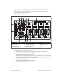
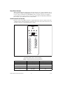
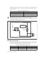
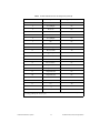
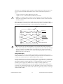
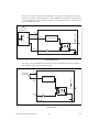
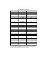
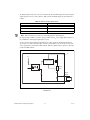
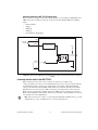
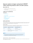
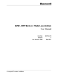
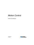
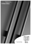
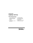
USER GUIDE AND SPECIFICATIONS NI UMI-7774/7772 This document provides information about the National Instruments Universal Motion Interface (UMI)-7774/7772 functionality and includes instructions for getting started, specifications, connection requirements, and safety information. Contents Introduction.......................................................................................................................................... 2 Features ........................................................................................................................................ 2 Safety Information ............................................................................................................................... 4 Electromagnetic Compatibility Information........................................................................................ 5 Related Documentation........................................................................................................................ 6 Installation ........................................................................................................................................... 6 Required Materials....................................................................................................................... 6 Optional Equipment..................................................................................................................... 7 Unpacking and Installing the UMI-7774/72................................................................................ 7 Noise Considerations ................................................................................................................... 9 Mounting the UMI-7774/72................................................................................................................. 9 Mounting the UMI-7774/72 on a DIN Rail ................................................................................. 10 Mounting the UMI-7774/72 on a Panel....................................................................................... 11 Mounting the UMI-7774/72 in a Standard 19 in. Rack ............................................................... 14 Connector Descriptions........................................................................................................................ 14 Power Input Terminal Block........................................................................................................ 14 Connecting Power To the UMI-7774/72 ............................................................................. 15 Power Status Indicators ............................................................................................................... 16 Control Connector for Each Axis ................................................................................................ 16 Analog Output...................................................................................................................... 17 Step (CW) and Dir (CCW) .................................................................................................. 17 Voltage Considerations for the UMI-7774/72 ..................................................................... 17 Fault ..................................................................................................................................... 18 Enable Output ...................................................................................................................... 20 Feedback Connector for Each Axis ............................................................................................. 22 Encoder ................................................................................................................................ 24 Limit and Home Inputs ........................................................................................................ 25 Limit and Home Status Indicators ....................................................................................... 27 Global Stop .................................................................................................................................. 28 Inhibit All............................................................................................................................. 28 Shutdown ............................................................................................................................. 28 Analog Input ................................................................................................................................ 28 Trigger/Breakpoint....................................................................................................................... 29 Trigger ................................................................................................................................. 29 Breakpoint............................................................................................................................ 29 General-Purpose Digital I/O ........................................................................................................ 30 Connecting Switches to UMI-7774/72 Sinking Inputs........................................................ 33 Connecting Inductive Loads to the UMI-7774/72....................................................................... 33 Servo Drive Modes .............................................................................................................................. 34 Specifications....................................................................................................................................... 34 Encoder Interface ......................................................................................................................... 35 Limit and Home Switch, Inhibit, Inhibit All, Shutdown, and General Purpose Digital Inputs... 35 Trigger Inputs .............................................................................................................................. 35 Axis Enable Outputs .................................................................................................................... 35 General Purpose Digital Outputs ................................................................................................. 36 Step/Direction/Breakpoint Outputs.............................................................................................. 36 Analog Inputs............................................................................................................................... 36 Analog Outputs ............................................................................................................................ 36 Host Bus Voltage Interlock.......................................................................................................... 36 Power Characteristics .................................................................................................................. 36 Environmental Conditions ........................................................................................................... 36 Shock and Vibration .................................................................................................................... 37 Physical Characteristics ............................................................................................................... 37 Safety ........................................................................................................................................... 37 Electromagnetic Compatibility .................................................................................................... 37 CE Compliance ............................................................................................................................ 37 Online Product Certification........................................................................................................ 38 Environmental Management........................................................................................................ 38 UMI-7774/72 Pinouts .......................................................................................................................... 39 Worldwide Support and Services ........................................................................................................ 40 Introduction The UMI-7774 and UMI-7772 (UMI-7774/72) are standalone connectivity accessories designed to be used with National Instruments 73xx series motion controllers for up to four axes of simultaneous or independent control. Ideally suited to industrial and laboratory applications, the UMI-7774/72 connects third-party stepper and servo drives (amplifiers) and/or feedback and digital I/O to National Instruments motion controllers. The UMI-7772 is a two-axis version of the UMI-7774. All illustrations, information, and specifications in this manual apply to both devices. Note For consistency, the remainder of this user manual refers only to drives. All references to drives also apply to amplifiers. You can use the UMI-7774/72 with a wide variety of drives designed for many types of motors or actuators and power ranges. This flexibility allows you to use the UMI-7774/72 in systems where you must use a third-party drive. To work correctly with the UMI-7774/72, drives must have industry standard interfaces. For stepper systems, the industry standard command signals are step and direction, or clockwise (CW) and counter-clockwise (CCW), pulse inputs. For servo systems, the industry standard command signal is a ±10 V analog input. Features The UMI-7774/72 simplifies field wiring by supplying a separate feedback and control D-SUB connector for each axis. The UMI-7774/72 connects the motion input and output to the motion controller through a single interface cable. You can connect the UMI-7774/72 digital inputs and outputs to the controller with a separate interface cable to provide access to up to eight digital inputs and NI UMI-7774/72 User Guide and Specifications 2 ni.com eight digital outputs on the controller. Also, the UMI-7774/72 features a host bus monitor power interlock that automatically disables the drive if the host computer is shut down or the motion input/output interface cable is disconnected. Figure 1 shows the UMI-7774. 1 2 3 4 5 6 12 FAULT FAULT FWD HOME ENABLE FAULT REV LIMIT LED FAULT FWD HOME ENABLE REV LIMIT LED FAULT FAULT FWD HOME ENABLE REV FAULT LIMIT LED FAULT FWD HOME ENABLE REV LIMIT LED 11 10 1 2 3 4 5 Power Connection LEDs Power Connector Global Stop D-SUB Analog Input D-SUB Per-Axis Polarity Switches 9 6 7 8 9 10 8 7 Per-Axis LED Status Indicators Per-Axis Control Connector Per-Axis Feedback Connector Trigger/Breakpoint Connector Digital I/O Connector 11 UMI to 73xx Controller Digital I/O Connector 12 UMI to 73xx Controller Motion I/O Connector Figure 1. UMI-7774/72 Connector, LED, and Switch Locations The UMI-7774/72 includes the following features: • D-SUB connectivity, which provides easy and durable connectivity to third-party devices. • 5 to 30 V limits and home switch/sensor compatibility. • Global Stop inputs for global shutdown of all axes. • Optical isolation on inhibit signals, Global Stop inputs, triggers, limits, home, and digital I/O. This feature enables 24 VDC signaling capability. Also, the isolation can help break ground loops in the system and reduce the effects of noise and voltage transients. • Global and per-axis status LEDs. • Access to eight digital inputs and eight digital outputs. • Panel, DIN rail, or rack mountable. © National Instruments Corporation 3 NI UMI-7774/72 User Guide and Specifications Safety Information Caution The following paragraphs contain important safety information you must follow when installing and operating the UMI-7774/72 and all devices connecting to the UMI-7774/72. Do not operate the device in a manner not specified in the documentation. Misuse of the device can result in a hazard. You can compromise the safety protection built into the device. If the device is damaged in any way, return the device to National Instruments for repair. Keep away from live circuits. Do not remove equipment covers or shields unless you are trained to do so. If signal wires are connected to the device, hazardous voltages can exist even when the equipment is turned off. To avoid a shock hazard, do not perform procedures involving cover or shield removal unless you are qualified to do so. Disconnect all field power prior to removing covers or shields. If the device is rated for use with hazardous voltages (>30 Vrms, 42.4 Vpk, or 60 Vdc), it may require a safety earth-ground connection wire. See the device specifications for maximum voltage ratings. Note Although some signal lines on the UMI-7774/72 have optical isolation to reduce noise effects and ground loops, the UMI-7774/72 does not include safety isolation features. Also, there is no isolation between signals, connectors, or axes on the UMI-7774/72 unless otherwise noted. Because of the danger of introducing additional hazards, do not substitute parts or modify the device. Use the device only with the chassis, modules, accessories, and cables specified in the installation instructions. All covers and filler panels must be installed while operating the device. Do not operate the device in an explosive atmosphere or where flammable gases or fumes may be present. If you must operate the device in such an environment, the device must be in a suitably rated enclosure. Operate the device only at or below Pollution Degree 2. Pollution consists of any foreign matter—solid, liquid, or gas—that may reduce dielectric strength or surface resistivity. The following is a description of pollution degrees: • Pollution Degree 1—No pollution or only dry, nonconductive pollution occurs. The pollution has no effect. • Pollution Degree 2—Normally only nonconductive pollution occurs. Occasionally, nonconductive pollution becomes conductive because of condensation. • Pollution Degree 3—Conductive pollution or dry, nonconductive pollution occurs. Nonconductive pollution becomes conductive because of condensation. Clean the device and accessories by brushing off light dust with a soft, nonmetallic brush. Remove other contaminants with a stiff, nonmetallic brush. The unit must be completely dry and free from contaminants before returning it to service. You must insulate signal connections for the maximum voltage for which the device is rated. Do not exceed the maximum ratings for the device. Remove power from signal lines before connection to or disconnection from the device. Operate this device only at or below the installation category1 marked on the hardware label. Measurement circuits are subjected to working voltages2 and transient stresses, such as overvoltage, from the circuit they are connected to during the measurement or test. Installation categories establish 1 Installation categories, also referred to as measurement categories, are defined in electrical safety standard IEC 61010-1. 2 Working voltage is the highest rms value of an AC or DC voltage that can occur across any particular insulation. NI UMI-7774/72 User Guide and Specifications 4 ni.com standard impulse withstand voltage levels that commonly occur in electrical distribution systems. The following is a description of installation categories: • Installation Category I is for measurements performed on circuits not directly connected to the electrical distribution system referred to as MAINS1 voltage. This category is for measurements of voltages from specially protected secondary circuits. Such voltage measurements include signal levels, special equipment, limited-energy parts of equipment, circuits powered by regulated low-voltage sources, and electronics. • Installation Category II is for measurements performed on circuits directly connected to the electrical distribution system. This category refers to local-level electrical distribution, such as that provided by a standard wall outlet (for example, 115 AC voltage for U.S. or 230 AC voltage for Europe). Examples of Installation Category II are measurements performed on household appliances, portable tools, and similar modules. • Installation Category III is for measurements performed in the building installation at the distribution level. This category refers to measurements on hard-wired equipment such as equipment in fixed installations, distribution boards, and circuit breakers. Other examples are wiring (including cables), bus bars, junction boxes, switches, socket outlets in the fixed installation, and stationary motors with permanent connections to fixed installations. Installation Category IV is for measurements performed at the primary electrical supply installation (<1,000 V). Examples include electricity meters and measurements on primary overcurrent protection devices and on ripple control units. Electromagnetic Compatibility Information This hardware has been tested and found to comply with the applicable regulatory requirements and limits for electromagnetic compatibility (EMC) as indicated in the hardware’s Declaration of Conformity (DoC)2. These requirements and limits are designed to provide reasonable protection against harmful interference when the hardware is operated in the intended electromagnetic environment. In special cases, for example when either highly sensitive or noisy hardware is being used in close proximity, additional mitigation measures may have to be employed to minimize the potential for electromagnetic interference. While this hardware is compliant with the applicable regulatory EMC requirements, there is no guarantee that interference will not occur in a particular installation. To minimize the potential for the hardware to cause interference to radio and television reception or to experience unacceptable performance degradation, install and use this hardware in strict accordance with the instructions in the hardware documentation and the DoC2. If this hardware does cause interference with licensed radio communications services or other nearby electronics, which can be determined by turning the hardware off and on, you are encouraged to try to correct the interference by one or more of the following measures: • 1 2 Reorient the antenna of the receiver (the device suffering interference). • Relocate the transmitter (the device generating interference) with respect to the receiver. • Plug the transmitter into a different outlet so that the transmitter and the receiver are on different branch circuits. MAINS is defined as a hazardous live electrical supply system that powers equipment. Suitably rated measuring circuits may be connected to the MAINS for measuring purposes. The Declaration of Conformity (DoC) contains important EMC compliance information and instructions for the user or installer. To obtain the DoC for this product, visit ni.com/certification, search by model number or product line, and click the appropriate link in the Certification column. © National Instruments Corporation 5 NI UMI-7774/72 User Guide and Specifications Some hardware may require the use of a metal, shielded enclosure (windowless version) to meet the EMC requirements for special EMC environments such as, for marine use or in heavy industrial areas. Refer to the hardware’s user documentation and the DoC1 for product installation requirements. When the hardware is connected to a test object or to test leads, the system may become more sensitive to disturbances or may cause interference in the local electromagnetic environment. Operation of this hardware in a residential area is likely to cause harmful interference. Users are required to correct the interference at their own expense or cease operation of the hardware. Changes or modifications not expressly approved by National Instruments could void the user’s right to operate the hardware under the local regulatory rules. Related Documentation The following documents contain information that you might find helpful as you read this manual. All referenced documents ship with the product and are available at ni.com/manuals. • Getting Started with NI-Motion for NI 73xx Motion Controllers—Provides installation instructions and general information about the NI-Motion product. • Getting Started with NI 7340/7350 Motion Controllers and AKD Servo Drives—Explains how to install and configure the AKD servo drives for use with the NI 7340 and NI 7350 motion controllers. • Getting Started with NI 7330/7340/7350 Motion Controllers and P7000 Series Stepper Drives—Explains how to install and configure the P7000 series steper drives for use with NI 7330, 7340, and NI 7350 motion controllers. • NI-Motion LabVIEW Help—Contains LabVIEW VI reference files and provides details about each VI, including VI descriptions, lists of control and input terminals, usage, illustrations, and error codes. • NI-Motion Function Help—Contains function reference files for C and Visual Basic and provides details about each function, including a description of the function, a list of the function parameters, illustrations, and error codes. • Measurement & Automation Explorer Help for Motion—Provides information about using MAX to configure the NI 73xx motion controller as well as some advanced conceptual information about topics such as Bode analysis and control loop parameters. • NI 73xx motion controller user manuals—Describes the electrical and mechanical aspects of the NI 73xx motion controller, and contains information about installing and operating the device. • Drive documentation Installation This section describes the required and optional items for getting started with the UMI-7774/72. This section also explains how to unpack, configure, and install the UMI-7774/72. Required Materials The following items are necessary for installing and getting started with the UMI-7774/72: ❑ UMI-7774 or UMI-7772. ❑ 24 ±10% VDC power supply (10 W minimum). 1 The Declaration of Conformity (DoC) contains important EMC compliance information and instructions for the user or installer. To obtain the DoC for this product, visit ni.com/certification, search by model number or product line, and click the appropriate link in the Certification column. NI UMI-7774/72 User Guide and Specifications 6 ni.com ❑ (Optional) 5 to 30 V isolated power supply (10 to 60 W minimum, depending on I/O requirements). Note The same power supply may be used for both the main +24 V power supply and I/O. However, if you use the same power supply for both connections, there will be no isolation between the I/O and the main power. ❑ National Instruments 73xx series motion controller and associated documentation. Refer to Getting Started with NI-Motion for NI 73xx Motion Controllers for detailed installation instructions. ❑ One of the following National Instruments SHC68-C68-S cables for connecting a motion controller to the UMI-7774/72: – 2 m (part number 186380-02) – 0.5 m (part number 186380-0R5) ❑ Custom cable for connecting the UMI-7774/72 to a third-party drive. Refer to the Noise Considerations section for cable creation requirements. ❑ One of the following drives and documentation: – – – – – AKD analog servo drive, 3A (NI part number 781520-01) AKD analog servo drive, 6A (NI part number 781522-01) P70530 DC stepper drive (NI part number 780097-01) P70360 AC stepper drive (NI part number 780098-01) Third-party drive ❑ Servo or stepper motor appropriate for the selected drive. Note NI offers brushless servo motors and feedback for direct connectivity to the AKD analog servo drives, and stepper motors for direct connectivity to the P7000 series stepper drives. Go to ni.com/motion for all available products. Optional Equipment National Instruments offers a variety of products for use with the UMI-7774/72, including the following: • Mounting accessories. Refer to the Mounting the UMI-7774/72 section for information about specific equipment for each available mounting package. • Separate +24 VDC power supply for isolated I/O. • Additional SHC68-C68-S cable (0.5 m or 2 m) with 68-pin VHDCI offset male connectors on both ends. Use this cable to connect the digital I/O connector on the National Instruments motion controller to the digital I/O connector on the UMI-7774/72. • 9-, 15-, and 25-pin D-SUB to flying lead cables (part number 190911-04, 19012-04, and 19013-04). Use these cables to connect the UMI-7774/72 D-SUB connectors to third-party drives and feedback devices. Unpacking and Installing the UMI-7774/72 The following steps provide a high-level overview for connecting the UMI-7774/72 with NI motion controllers, drives, and other I/O. Refer to Figure 1 for the UMI-7774/72 connector, LED, and switch locations. Note The UMI-7774/72 ships in an antistatic package to prevent electrostatic discharge from damaging device components. 1. 2. Remove the UMI-7774/72 from the package. Inspect the UMI-7774/72 for loose components or any other signs of damage. Contact National Instruments if the device appears damaged in any way. © National Instruments Corporation 7 NI UMI-7774/72 User Guide and Specifications Caution Do not touch exposed connector pins. Doing so may cause damage to the device. 3. Mount the UMI-7774/72, if necessary. Refer to the Mounting the UMI-7774/72 section for mounting options. 4. Connect the UMI-7774/72 to the NI 73xx motion controller by connecting one end of the SHC68-C68-S cable to the 68-pin motion I/O connector on the motion controller and the other end to the 68-pin motion I/O connector on the UMI-7774/72. Refer to Figure 2 for a connection diagram. 1 3 PO WE V S OB TRUNAL AL ME ST OP NTS L GL Vis o CONTROLLER DIGITAL I/O 5 N INATIO R MOTION I/O 2 INH 24VD V C ±1 IBI T AL 0% C Vi (5– so 30VD C) Ciso INT ER LO CK AX IS GLO L ST OP X NI AB FA UL T LE D FW AC TIV LO E W VD C MA 1 DIS BA PO 28 WER D HO ALO V AC TIV HIGHE EN AB LE PU T LIM TR IGG I-7 774 IS RE G IN RS AB LE D FW IT LE AC TIV LO E W D KPO ME IS RE V AC TIV HIGHE LIM DIG 4 MO TIO AX HO EN AB LE INT AL D FA UL T EA ITA L UN IVE 2 DIS FA UL T ER /BR UM AX ME FA UL T AN IT LE N IN 3 TE RF AC E DIS AB FA UL T AC TIV LO E W D LE D FW D HO V LIM CO ED BA CK IS RE AC TIV HIGHE EN AB LE FE AX ME FA UL T I/O NTR OL 4 DIS AB LE FA UL T D FW IT LE D AC TIV LO E W D HO ME RE FA UL T V AC TIV HIGHE EN AB LE CO FE ED BA CK LIM NTR OL 6 ED BA CK CO BA CK 4 5 6 D NTR OL ED NI 73xx Series Motion Controller NI 73xx Motion I/O Connector UMI-7774/72 Motion I/O Connector LE CO FE FE 1 2 3 IT NTR OL UMI-7774/72 Digital I/O Connector SHC68-C68-S Cable NI 73xx Digital I/O Connector Figure 2. UMI-7774/72 Connected to an NI 73xx Series Motion Controller 5. Connect a 24 VDC power supply to the UMI-7774/72 V and C terminals. Refer to Power Status Indicators for more information. 6. (Optional) Connect a separate 5 to 30 VDC power supply to the Viso and Ciso terminals to use the isolation feature of the UMI-7774/72. Refer to Power Status Indicators for more information. Note If you do not connect a separate power supply to the Viso and Ciso terminals you must connect the V and Viso terminal together and connect the C and Ciso terminal together. 7. Connect the UMI-7774/72 to a stepper or servo drive. Refer to the Connector Descriptions section for detailed information about the connectors including voltage considerations and wiring diagrams. Note NI offers direct connect cables to connect the AKD analog servo drives or the P7000 series stepper drives to the UMI-7774/72. Go to ni.com/motion for all available products. 8. Connect any additional I/O to the UMI-7774/72 including limits, DIO, trigger inputs, and breakpoint outputs. Refer to the Connector Descriptions section for detailed information about the connectors including voltage considerations and wiring diagrams. 9. Test the signal connections starting with the limit and home switches, then the encoders, and finally the inhibit and command connections. NI UMI-7774/72 User Guide and Specifications 8 ni.com Figure 3 shows a simplified connection diagram. (Optional) 5 - 30 V Power Supply for Isolation Per-Axis UMI to Drive Connections SHC68-C68-S Cable Stepper or Servo Drive UMI-7772/74 NI 73xx Motion Controller Additional I/O (Such As Limits, DIO, Trigger Inputs, Breakpoint Outputs) +24 V Power Supply (NI PS-15 Shown) Figure 3. UMI-7774/72 Connection Diagram Note Refer to the Getting Started with NI 7340/7350 Motion Controllers and AKD Servo Drives or the Getting Started with NI 7330/7340/7350 Motion Controllers and P7000 Series Stepper Drives for connection diagrams specific to those devices. Noise Considerations Before connecting the UMI-7774/72, verify that all system components are grounded correctly and that all wiring is properly shielded. Do not connect high-voltage wires and low-level signals to the same channel. The following list includes additional noise considerations. Caution Failure to follow these precautions may result in system instability and may cause permanent damage to system components. • Keep high voltage lines, such as AC power cables and motor drive cables, away from low-level signals, such as encoders and limits. • Use twisted pair cable for differential signals, such as encoders. • Ensure that all cables connected to the UMI-7774/72 include a braided shield. • Use hoods with internal metallic shielding for D-SUB connectors. • Ensure that all devices in the system, including the UMI-7774/72, drives, and motors, are properly grounded. • Ensure that all power supplies and motor drives in the system are powered down when connecting them to the UMI-7774/72. Mounting the UMI-7774/72 You can mount the UMI-7774/72 on a 35 mm DIN rail, on a panel, or in a standard 19 in. rack. The following sections include instructions for all three mounting methods. Before using any of these mounting methods, record the serial number from the back of the UMI-7774/72. You will be unable to read the serial number after you have mounted the UMI-7774/72. Caution When you mount the UMI-7774/72 and connect cables to it, allow 51–76 mm (2–3 in.) of space between each side of the device and any other surface to ensure appropriate air circulation. © National Instruments Corporation 9 NI UMI-7774/72 User Guide and Specifications Note The external dimensions for the UMI-7772 are the same as the dimensions for the UMI-7774, shown in Figure 4 and Figure 5. FAULT FAULT FWD HOME ENABLE REV FAULT LIMIT LED FAULT FWD HOME ENABLE REV LIMIT LED FAULT FAULT FWD HOME ENABLE REV FAULT LIMIT LED FAULT FWD HOME ENABLE REV LIMIT LED 5.000 in. (126.93 mm) 10.200 in. (259.08 mm) Figure 4. UMI-7774, Front View with Dimensions 0.867 in. (22.01 mm) 10.200 in. (259.08 mm) Figure 5. UMI-7774, Side View with Dimensions Mounting the UMI-7774/72 on a DIN Rail The UMI-7774/72 has one clip for mounting on a standard 35 mm DIN rail. You can order the DIN rail mounting kit (part number 778710-01) from National Instruments. Complete the following steps to mount the UMI-7774/72 on a DIN rail. Caution To prevent damage to the UMI-7774/72, do not use screws longer than 0.25 in. to fasten the DIN rail clip to the UMI-7774/72. 1. Fasten the DIN rail clip to the UMI-7774/72 using a number 2 Phillips screwdriver and the two 8-32 0.25 in. countersink screws shipped with the DIN rail clip as shown in Figure 6. These screws have a nylon coating to prevent them from loosening. NI UMI-7774/72 User Guide and Specifications 10 ni.com L NA NTS TIO E NATRUM INS Figure 6. Fastening the DIN Rail Clip to the UMI-7774/72 2. Insert one edge of the DIN rail into the deeper opening of the DIN rail clip, as shown in Figure 7. 3. Press down firmly on the UMI-7774/72 to compress the spring until the clip locks in place on the DIN rail. 1 2 3 1 DIN Rail Clip 2 DIN Rail Clip Spring 3 DIN Rail Figure 7. One Edge of DIN Rail Inserted in Clip Caution Disconnect power before removing the UMI-7774/72 from the DIN rail. Mounting the UMI-7774/72 on a Panel You must use a panel-mount kit to mount the UMI-7774/72 on a panel. You can order the appropriate kit (part number 778709-01 or 778711-01) from National Instruments. Complete the following steps to install the panel-mount kit. Caution Do not use screws longer than 0.25 in. to fasten the panel-mount accessory brackets to the UMI-7774/72. © National Instruments Corporation 11 NI UMI-7774/72 User Guide and Specifications 1. Fasten the two brackets of the panel-mount kit to the back of the UMI-7774/72 using a number 2 Phillips screwdriver and the 8-32 .25 in. countersink screws shipped with the panel-mount kit. These screws have a nylon coating to prevent them from loosening. Refer to Figures 8, 9, 10, and 11 for illustrations of mounting the UMI-7774/72 on a panel. L NA NTS TIO E NATRUM INS Figure 8. Fastening the Horizontal Panel-Mount Brackets to the UMI-7774/72 L NA TS TIO EN NA RUM INST Figure 9. Fastening the Vertical Panel-Mount Brackets to the UMI-7774/72 2. Attach the panel-mount accessory to a panel using 8-32 or M4 screws. Note The external dimensions for the UMI-7772 are the same as the dimensions for the UMI-7774, shown in Figure 10 and Figure 11. NI UMI-7774/72 User Guide and Specifications 12 ni.com 11.000 in. (279.4 mm) FAULT LIMIT LED FWD HOME FAULT REV FAULT FWD LIMIT LED ENABLE HOME FAULT REV FAULT ENABLE LIMIT LED FWD HOME FAULT FAULT REV ENABLE FWD LIMIT LED HOME FAULT REV ENABLE Figure 10. UMI-7774/72 Front View with Horizontal Panel Mount Dimensions 6 in. (152 mm) FAULT LIMIT LED FWD HOME FAULT REV ENABLE FAULT LIMIT LED FWD HOME FAULT REV ENABLE FAULT LIMIT LED FWD HOME FAULT REV ENABLE FAULT LIMIT LED FWD HOME FAULT REV ENABLE 7 in. (178 mm) Figure 11. UMI-7774/72 Front View with Vertical Panel Mount Dimensions Caution Disconnect power before removing the UMI-7774/72 from the panel. © National Instruments Corporation 13 NI UMI-7774/72 User Guide and Specifications Mounting the UMI-7774/72 in a Standard 19 in. Rack To mount the UMI-7774/72 in an EIA-standard 19 in. rack, you must use the rack-mount kit (part number 778712-01) from National Instruments. Complete the following steps to install the rack-mount kit. 1. Fasten the rack-mount bracket to the back of the UMI-7774/72 using the captive screws on the bracket. ALL TS TION EN NA RUM INST Figure 12. Fastening the Rack-Mount Accessory to the UMI-7774/72 2. Bolt the rack-mount accessory to a standard 19 in. rack. Caution Disconnect power before removing the UMI-7774/72 from the rack. Connector Descriptions This section describes how to wire National Instruments motion controllers, third-party drives, sensors, and field I/O to the UMI-7774/72. This section also describes the polarity (active state) settings and LED indicators on the UMI-7774/72. Refer to Figure 1 for the UMI-7774/72 connector, LED, and switch locations. Power Input Terminal Block The UMI-7774/72 requires a 24 VDC power supply to operate. The UMI-7774/72 has a 4-position terminal block for wiring 24 VDC power and 5 to 30 VDC isolated power to the UMI-7774/72. The isolated power is used in the optical isolation output circuitry for the drive enable outputs and digital output signals. Optical isolation is a method for transmitting a signal from its source to a measurement device without a physical connection by using an optical coupling technique. Optical isolation can help break ground loops in the system and reduce the effects of noise and voltage transients. NI UMI-7774/72 User Guide and Specifications 14 ni.com Caution Do not connect the UMI-7774/72 isolated power to a source greater than 30 V. Doing so may cause damage to UMI-7774/72 components. Viso and Ciso are redistributed to other connectors on the UMI-7774/72 as an output power source for external devices. Refer to Figure 1 to locate the power input terminal block on the UMI-7774/72. Figure 13 shows the 4-position power connector. Table 1 shows the power connector terminal block pinout. Table 1 includes descriptions of each of the terminals on the UMI-7774/72 power connector. Table 1. Power Connector Terminals Terminal Description V Main power (24 V ±10%) C Common Viso Isolated power (5 to 30 VDC) Ciso Isolated common If you do not connect a separate power supply to the Viso and Ciso terminals you must connect the V and Viso terminal together and connect the C and Ciso terminal together. Note When the drive enable output and digital output signals are in an ON state, they provide the power connected on Viso and Ciso. Use a power supply with a voltage that is compatible with the inputs that the drive enable and digital outputs are connected to. Viso and Ciso do not provide safety isolation. Connecting Power To the UMI-7774/72 The UMI-7774/72 includes a 4-position power connector that provides voltage and common for the main power supply as well as voltage and common for the isolated output circuitry. V C o Vis o Cis Figure 13. UMI-7774/72 Power Input Complete the following steps to wire power to the UMI-7774/72. 1. Connect the positive lead of the 24 VDC power supply to the V terminal and the negative lead to the C terminal on the UMI-7774/72. 2. If you are using a separate power supply for optical isolation, connect the positive lead of the 5–30 VDC supply to the Viso terminal and the negative lead to the Ciso terminal on the UMI-7774/72. 3. If you are not using the isolation feature on the UMI-7774/72, you must connect the V and Viso terminal together and connect the C and Ciso terminal together. © National Instruments Corporation 15 NI UMI-7774/72 User Guide and Specifications Power Status Indicators When you finish making the required power connections to the V, C, Viso, and Ciso terminals, power on the 24 VDC power supply. The V LED illuminates. If the 24 VDC power supply has also been connected to the Viso and Ciso terminals, the Viso LED illuminates. If you are using a separate power supply to provide isolation, power on the separate 5 to 30 V power supply and the Viso LED indicator illuminates. Refer to Figure 1 for an illustration of the V and Viso LEDs. Control Connector for Each Axis Each axis connected to the UMI-7774/72 has a 15-pin D-SUB control connector to which you wire drive command and drive enable signals. Figure 14 shows the pin locations of the control connector for each axis. Table 2 shows the corresponding signals for each pin. AXIS 1 DISABLED FAULT FWD HOME ACTIVE LOW FAULT ENABLE LIMIT LED 1 1 2 3 4 5 6 7 8 9 10 11 12 13 REV ACTIVE HIGH 14 2 15 3 16 4 17 5 18 6 19 7 20 8 9 10 11 12 13 14 15 21 22 CONTROL 23 24 25 FEEDBACK Figure 14. UMI-7774/72 Per Axis Control and Feedback Connectors, LED Status Indicators, and Polarity Switches (Axis 1 Shown as Example) Table 2. Per Axis Control Connector Pin Assignment Pin Signal Optically Isolated 1 Analog Output No NC No 2 3 4 NI UMI-7774/72 User Guide and Specifications +5 V† (Output) Step (CW) 16 No No ni.com Table 2. Per Axis Control Connector Pin Assignment (Continued) Pin Signal Optically Isolated 5 NC No 6 Enable Yes 7 Fault + Yes 8 Viso (Output) Yes 9 Analog Output Ground No 10 Digital Ground No 11 Digital Ground No 12 Dir (CCW) No 13 NC No 14 Fault – Yes 15 Ciso Yes † Provides 1 A maximum output current, shared between Control connector pin 3, Feedback connector pins 4 and 8, and Trigger/Breakpoint connector pin 3. Analog Output The UMI-7774/72 analog output signals are used as command outputs to servo drives or as general-purpose voltage outputs. To help keep digital noise separate from the analog outputs, Pin 9 provides a separate analog output ground connection. Use this analog ground connection instead of a digital ground when you connect the UMI-7774/72 to servo drives. Analog outputs are pass-through signals from the motion controller. A pass-through signal provides passive filtering on the signals, which does not affect the voltage range or current-handling capability of the signals. Step (CW) and Dir (CCW) The UMI-7774/72 Step (CW) and Dir (CCW) signals are used as command outputs to a stepper drive. Some stepper drives require clockwise direction (CW) and counterclockwise direction (CCW) commands rather than Step and Dir commands. You can configure National Instruments motion controllers to provide either type of stepper commands. Both Step (CW) and Dir (CCW) signals are pass-through signals. Voltage Considerations for the UMI-7774/72 To cause current to flow through the input, the voltage applied to the following types of inputs must be greater than 3.5 V and less than 30 V. • Fault inputs • Limit and home inputs • Global Stop inputs • Trigger inputs • General-purpose digital inputs Also, the source must be able to provide at least 7.2 mA to turn on the optical isolator and result in an ON condition. When the applied voltage is below 2 V, the input results in an OFF condition. © National Instruments Corporation 17 NI UMI-7774/72 User Guide and Specifications Fault The Fault signal is an optically isolated digital input. If the Fault input signal is asserted, the DISABLED LED is lit and the Enable output signal is deactivated. Refer to Figure 14 for the location of the axis status LEDs. You can configure the axis Fault input signals as active low or active high inputs using the switch for the axis labeled FAULT. The down position of the switch corresponds to active low and the up position of the switch corresponds to active high. Refer to Figure 14 for the location of the axis polarity switches. Note Figure 19 shows a simplified connection diagram for the Enable, Fault, and Global Stop inputs. To cause current to flow through the input, the voltage applied to the fault input must be greater than 3.5 V and less than 30 V. Also, the source must be able to provide at least 7.2 mA to turn on the optical isolator and result in an ON condition. When the applied voltage is below 2 V, the input results in an OFF condition. You can wire the Fault input to either a current sourcing or sinking output from a drive or other device. Refer to Figure 15 and Figure 16 for examples of wiring the Fault input signal to sourcing and sinking output devices. In both cases, the isolated power (Viso) and isolated common (Ciso) signals provided on the control connector are used to power the external devices. PNP (Sourcing) Output Device Viso V+ Vcc Fault + Out Current Limiter V– Fault – Ciso UMI-7774/72 Figure 15. Example of Wiring a Sourcing Output Device to the Fault Input NI UMI-7774/72 User Guide and Specifications 18 ni.com Viso Vcc Fault + Current Limiter NPN (Sinking) Output Device V+ Fault – Out Ciso V– UMI-7774/72 Figure 16. Example of Wiring a Sinking Output Device to the Fault Input You can also use a manual operator switch to handle disabling an axis. Refer to Figure 17 and Figure 18 for examples of wiring the fault input signal to high-side and low-side switches. Viso High-Side Switch Fault + Current Limiter Vcc Fault – Ciso UMI-7774/72 Figure 17. Example of Wiring a High-Side Switch to the Fault Input © National Instruments Corporation 19 NI UMI-7774/72 User Guide and Specifications Viso Vcc Fault + Current Limiter Fault – Low-Side Switch Ciso UMI-7774/72 Figure 18. Example of Wiring a Low-Side Switch to the Fault Input Enable Output The Enable output signal is an optically isolated digital output used to enable or disable the drive for the axis. The Enable signal for the axis is deactivated when any of the following signals are asserted: • Host Bus Interlock (global) • Inhibit All (user-supplied and global) • User-supplied external Fault input (per axis) • Controller Axis Inhibit Out (per axis) • Controller Shutdown (if enabled on the controller) If the Enable output signal is deactivated for any reason, the DISABLED LED illuminates. If the Fault input signal is also active, both the FAULT and the DISABLED LEDs for the axis illuminate. Refer to Figure 14 for the locations of these LEDs. Refer to the Global Stop section for information about the Inhibit All and Shutdown signals. The host bus interlock is a safety feature that is not user-configurable. It monitors the +5 V pin from the motion controller to verify that the motion controller is powered on and properly connected to the UMI-7774/72. NI UMI-7774/72 User Guide and Specifications 20 ni.com You can configure the axis Enable output signal as active low or active high using the ENABLE switch. Refer to Figure 14 for the location of this switch. The down position for the switch corresponds to active low and the up position for the switch corresponds to active high. Table 3 shows the enable output pin voltage at different ENABLE switch settings. Table 3. Enable Output Voltage and Switch Settings Enable Signal State ENABLE Switch Setting on UMI Enable Output Voltage Level Activated Active Low Viso Active High Open Active Low Open Active High Viso Deactivated Note You must configure the NI 73xx motion controller Inhibit Out signals as active low for proper operation of the inhibit logic on the UMI-7774/72. This is the default setting for these signals. Figure 19 shows a simplifed connection diagram for the Enable, Fault, and Global Stop signals. Controller UMI-7774/72 Host Bus Interlock Shutdown 4 Motion I/O Connector Axis 1 Axis Inhibit Enable Drive 1 Fault Axis 2 Enable Drive 2 Fault Global Stops Shutdown User Supplied Inhibit_All Figure 19. Fault, Enable, and Global Stop Wiring Diagram Note If you are connecting the Enable output to inductive loads, such as relays and solenoids, special precautions may be necessary. Refer to the Connecting Inductive Loads to the UMI-7774/72 section for more information. © National Instruments Corporation 21 NI UMI-7774/72 User Guide and Specifications The Enable output circuit provides a current source to an external device. The maximum output current for the Enable output depends on the Viso voltage. Refer to Table 4 for the maximum output current at different Viso voltages. Table 4. Maximum Available Output Current Note Viso Maximum Output Current (mA) 30 V 160 mA 24 V 150 mA 5V 60 mA If the load current exceeds the over current trip point, the output shuts off. The output voltage is within 1.2 V of the voltage provided on the Viso power supply. Refer to Figure 20 for an illustration of the Enable output interface circuit. Viso Vcc Current Limiter Current Sense Digital Output Load Ciso UMI-7774/72 Figure 20. UMI-7774/72 Optically Isolated Digital Output Circuit and Connection to an External Device Feedback Connector for Each Axis Each axis connected to the UMI-7774/72 has a 25-pin D-SUB feedback connector to which you can wire incremental encoders, limits, and home sensors. Figure 14 shows the pin locations of the feedback connector for each axis. Table 5 shows the corresponding signals for each pin. Table 5. Per Axis Feedback Connector Pin Assignment Pin Signal Optically Isolated 1 Encoder Phase A No 2 Encoder Phase B No NI UMI-7774/72 User Guide and Specifications 22 ni.com Table 5. Per Axis Feedback Connector Pin Assignment (Continued) Pin Signal Optically Isolated 3 Encoder Index No 4 +5 V (Output)† No 5 Reserved No 6 Reserved No 7 Reserved No 8 +5 V (Output)† No 9 NC No 10 Forward Limit Yes 11 Home Input Yes 12 Reverse Limit Yes 13 Viso (Output) Yes 14 Encoder Phase A– No 15 Encoder Phase B– No 16 Encoder Index– No 17 Digital Ground No 18 Digital Ground No 19 Digital Ground No 20 Digital Ground No 21 NC No 22 Ciso Yes 23 Ciso Yes 24 Ciso Yes 25 Ciso Yes † Provides 1 A maximum output current, shared between Control connector pin 3, Feedback connector pins 4 and 8, and Trigger/Breakpoint connector pin 3. © National Instruments Corporation 23 NI UMI-7774/72 User Guide and Specifications Encoder The UMI-7774/72 works only with encoders that have differential line or complementary driver outputs. Refer to Figure 21 for an illustration of the encoder input interface circuit. The UMI-7774/72 supports differential inputs for Phase A, Phase B, and Index signals. Phase A + Phase A Phase A 120 Ω – Phase B + Phase B Phase B 120 Ω – Index + Index 120 Ω Index – UMI-7774/72 Figure 21. UMI-7774/72 Encoder Input Interface Circuit Note The UMI-7774/72 does not support single-ended encoders. The differential encoder signals are converted to single-ended signals by a differential-to-single-ended converter on the UMI-7774/72 and are then passed through to the NI 73xx motion controller. You can accommodate encoders with various phase relationships by swapping the signal connections and/or connecting them to the inverting inputs as required by the application. A +5 V output, generated by the UMI-7774/72 internal power supply, is also available on the connector for powering encoders. This output provides 1 A maximum output current shared between Control connector pin 3, Feedback connector pins 4 and 8, and Trigger/Breakpoint connector pin 3. Figure 22 shows the default encoder phasing for NI 73xx motion controllers. Use Measurement & Automation Explorer (MAX) or the NI-Motion driver software to configure the motion controller encoder input signals. Phase A Phase B Index Figure 22. Encoder Signal Phasing, CW (Forward) Direction NI UMI-7774/72 User Guide and Specifications 24 ni.com Closed-loop servo applications require consistent directional polarity between the motor and encoder for correct operation. The National Instruments motion control standard directional polarity is as follows: • Positive = forward = clockwise (CW) facing motor shaft • Negative = reverse = counterclockwise (CCW) facing motor shaft Caution Use a shielded cable to prevent noise from corrupting the encoder signals. Noise on the encoder lines can result in lost counts, reduced accuracy, and other erroneous encoder and motion controller operations. When connecting the encoder signals to the UMI-7774/72, use shielded wire of at least 24 AWG. National Instruments recommends you use cables with twisted pairs and an overall shield for improved noise immunity and signal integrity. Figure 23 shows twisted pairs in a shielded cable. Drain Shield Encoder A Encoder A Encoder B Encoder B Encoder Index Encoder Index +5 V Digital Ground Figure 23. Shielded Twisted Pairs Note Some drives have pass-through signaling on encoders. If the drive has the pass-through feature, ensure that the drive does not filter the encoder signals because this could reduce achievable closed-loop performance and stability for the system. If the drive does not have pass-through signaling for encoders or if you choose not to use the pass-through signaling, you can connect the UMI-7774/72 to the encoders directly. Limit and Home Inputs The UMI-7774/72 has connections available for forward limit, reverse limit, and home sensors or switches. The limit sensors or switches are typically located at physical ends of travel. The home sensor or switch can be located at any reference position within the range of travel. The limits and home inputs are optically isolated sinking inputs on the UMI-7774/72. A sinking input is an input terminal that can sink current by providing a path to a supply common or ground. You can wire this type of input to a sourcing output device. A sourcing output device can source current by providing a path to a supply source. PNP sensors are examples of sourcing output devices. To cause current to flow through the input, the voltage applied to the limit and home inputs must be greater than 3.5 V and less than 30 V. Also, the source must be able to provide at least 7.2 mA to turn on the optical isolator and result in an ON condition. When the applied voltage is below 2 V, the input results in an OFF condition. © National Instruments Corporation 25 NI UMI-7774/72 User Guide and Specifications The interface circuit is the same for the forward limits, reverse limits, and home inputs. As shown in Figure 24, you can wire a sourcing output device, such as a PNP sensor, to the limit or home inputs. You can use the isolated power (Viso) and isolated common (Ciso) signals provided on the control connector to power the limit home sensor. PNP (Sourcing) Output Device Viso V+ Out Vcc Out Input Current Limiter V– Ciso UMI-7774/72 Figure 24. UMI-7774/72 Optically Isolated Sinking Input Interface Circuit and Connection to Sourcing Output Sensor You can also connect the limit and home inputs to a high-side switch. Figure 25 shows an example of wiring the limit or home input to a high-side switch. High-Side Limit Switch Viso Current Limiter Digital Input Vcc Ciso UMI-7774/72 Figure 25. UMI-7774-7772 Optically Isolated Sinking Input Interface Circuit and Connection to High-Side Switch NI UMI-7774/72 User Guide and Specifications 26 ni.com Caution Failure to properly connect the limit and home inputs may result in motion that stops at a limit, but then travels through it, potentially damaging the motion system. Incorrectly wired limits may prevent motion from occurring at all. For the end of travel limits to function correctly, the forward limit must be located at the forward or positive end of travel, and the reverse limit must be located at the negative end of travel. Limit and Home Status Indicators The UMI-7774/72 has yellow status LEDs for the forward limit, reverse limit, and home input signals. Refer to Figure 14 for the location of these LEDs. You can configure the limit and home status LEDs as active low or active high using the switch for the axis labeled LIMIT LED. The down position of the switch corresponds to active low and the up position of the switch corresponds to active high. Note Configuring the limit and home status LEDs on the UMI-7774/72 does not configure the limit and home inputs themselves as active high or active low. You must configure the limit and home inputs separately on the NI 73xx motion controller using MAX or the NI-Motion driver software. The yellow status LEDs for the limits and home inputs illuminate when the inputs are active. POWER V GLOBAL STOP Viso INHIBIT ALL 5 4 INTERLOCK 3 2 1 V (24 VDC ±10%) C 9 Viso (5 - 30 VDC) 8 7 6 GLOBAL STOP Ciso 5 4 3 2 1 POWER 30 VDC MAX 9 8 7 6 5 4 3 2 15 14 13 12 11 10 8 7 6 ANALOG INPUT 1 9 TRIGGER/BREAKPOINT 13 12 11 10 9 8 7 6 5 4 3 2 1 25 24 23 22 21 20 19 18 17 16 15 14 DIGITAL I/O Figure 26. UMI-7774/72 Pin Locations for Global Stop, Analog Input, Trigger/Breakpoint, and Digital I/O Connectors © National Instruments Corporation 27 NI UMI-7774/72 User Guide and Specifications Global Stop The UMI-7774/72 has a single 9-pin D-SUB connector for global stop wiring. This connector includes the Inhibit All input and the Shutdown input signals. Both signals are optically isolated sinking inputs. Refer to Figure 26 for the pin locations of the Global Stop connector and to Table 6 for the corresponding signals for each pin. Refer to Figure 1 to locate the Global Stop connector on the UMI-7774/72. Note Figure 19 shows a simplified connection diagram for the Enable, Fault, and Global Stop inputs. Inhibit All The Inhibit All signal acts as a global inhibit, and when asserted, deactivates the Enable outputs for all the axes on the UMI-7774/72. Shutdown The Shutdown signal is passed through to the motion controller and is typically used to disable the controller. Table 6. Global Stop Connector Pin Assignment Pin Signal Optically Isolated 1 Shutdown Yes 2 Inhibit All Yes 3 NC No 4 NC No 5 Viso (Output) Yes 6 Ciso Yes 7 Ciso Yes 8 Ciso Yes 9 Ciso Yes Both the Shutdown and Inhibit All inputs are sinking inputs on the UMI-7774/72 and are optically isolated. You can wire the Shutdown and Inhibit All inputs to a sourcing output device, such as a PNP sensor, as shown in Figure 24, or to a high-side switch as shown in Figure 28. You can use the isolated power (Viso) and isolated common (Ciso) signals on the control connector to power the sensor. To cause current to flow through the input, the voltage applied to the Shutdown and Inhibit All inputs must be greater than 3.5 V and less than 30 V. Also, the source must be able to provide at least 7.2 mA to turn on the optical isolator and result in an ON condition. When the applied voltage is below 2 V, the input results in an OFF condition. Analog Input The UMI-7774/72 has a single 9-pin D-SUB connector that provides access to the four analog input channels on the motion controller. The analog inputs are pass-through signals on the UMI-7774/72. Refer to Figure 1 to help you locate the analog input connector on the UMI-7774/72. Figure 26 shows the pin locations for the Analog Input connector. Table 7 shows the corresponding signals for each pin. NI UMI-7774/72 User Guide and Specifications 28 ni.com Table 7. Analog Input Connector Pin Assignment Note Pin Signal 1 Analog Input 1 2 Analog Input 2 3 Analog Input 3 4 Analog Input 4 5 Analog Reference (Output) 6 Analog Input Ground 7 Analog Input Ground 8 Analog Input Ground 9 Analog Input Ground None of the analog inputs are optically isolated. Trigger/Breakpoint The UMI-7774/72 has a single 15-pin D-SUB connector you can use for trigger input and breakpoint output wiring. This connector provides access to four trigger inputs and four breakpoint outputs. Refer to Figure 26 for the pin location of the Trigger/Breakpoint connector and to Table 8 for the corresponding signals for each pin. Refer to Figure 1 to locate the Trigger/Breakpoint connector on the UMI-7774/72. Trigger The UMI-7774/72 provides optical isolation on the trigger inputs. You can use the isolated power output and isolated common on the connector to power on the field devices or sensors that provide the trigger signals. All of the trigger inputs on the UMI-7774/72 are sinking inputs and are optically isolated. You can wire the trigger input to a sourcing output device such as a PNP sensor, as shown in Figure 24, or to a high-side switch as shown in Figure 28. Breakpoint The breakpoint outputs are pass-through signals on the UMI-7774/72. The breakpoint connector includes both a +5 V output and digital ground. Table 8. Trigger/Breakpoint Connector Pin Assignment Pin Signal Optically Isolated 1 Breakpoint 1 No 2 Breakpoint 3 No 3 +5 V (Output)† No 4 Digital Ground No 5 Ciso Yes © National Instruments Corporation 29 NI UMI-7774/72 User Guide and Specifications Table 8. Trigger/Breakpoint Connector Pin Assignment (Continued) Pin Signal Optically Isolated 6 Trigger 1 Yes 7 Trigger 3 Yes 8 Viso (Output) Yes 9 Breakpoint 2 No 10 Breakpoint 4 No 11 Digital Ground No 12 NC No 13 Trigger 2 Yes 14 Trigger 4 Yes 15 Ciso Yes † Provides 1 A maximum output current, shared between Control connector pin 3, Feedback connector pins 4 and 8, and Trigger/Breakpoint connector pin 3. Refer to the appropriate National Instruments motion controller documentation for information about trigger inputs and breakpoint outputs. To cause current to flow through the input, the voltage applied to the trigger inputs must be greater than 3.5 V and less than 30 V. Also, the source must be able to provide at least 7.2 mA to turn on the optical isolator and result in an ON condition. When the applied voltage is below 2 V, the input results in an OFF condition. General-Purpose Digital I/O The UMI-7774/72 routes 16 of the general-purpose digital I/O lines of the National Instruments motion controller to a single 25-pin D-SUB connector. All 16 digital I/O signals are optically isolated on the UMI-7774/72. These signals are configurable as inputs and/or outputs on the National Instruments motion controller. Use MAX or the NI-Motion driver software to configure the bits on port 1 as inputs and the bits on port 2 as outputs. To access the 16 (eight inputs and eight outputs) digital I/O signals on the National Instruments motion controller, connect one end of an additional SHC68-C68-S cable to the 68-pin digital I/O connector on the motion controller and the other end to the 68-pin digital I/O connector on the UMI-7774/72. Note To access all of the 32 digital I/O signals on the motion controller, you can connect the digital I/O connector on the motion controller to other National Instruments accessories. For example, you can connect the digital I/O on the National Instruments motion controller to an SSR cable adapter and then connect that adapter to the National Instruments SSR Series backplanes for use with other National Instruments devices, such as DAQ devices. In this case, you do not typically connect anything to the UMI-7774/72 digital I/O connector. The 8 bits from the first port on the motion controller (Port 1: bits 0–7) become sinking inputs on the UMI-7774/72, and the 8 bits from the second port of the motion controller (Port 2: bits 0–7) become sourcing outputs on the UMI-7774/72. Refer to Figure 26 for the pin locations of the Digital I/O NI UMI-7774/72 User Guide and Specifications 30 ni.com connector and to Table 9 for the corresponding signals for each pin. Refer to Figures 24 through 29 for information on how to wire the digital inputs and outputs on the UMI-7774/72. Table 9. Digital I/O Connector Pin Assignment Pin Signal Optically Isolated 1 Digital Input 0 Yes 2 Digital Input 2 Yes 3 Digital Input 4 Yes 4 Digital Input 6 Yes 5 Viso (Output) Yes 6 Viso (Output) Yes 7 NC No 8 Digital Output 0 Yes 9 Digital Output 2 Yes 10 Digital Output 4 Yes 11 Digital Output 6 Yes 12 Viso (Output) Yes 13 Viso (Output) Yes 14 Digital Input 1 Yes 15 Digital Input 3 Yes 16 Digital Input 5 Yes 17 Digital Input 7 Yes 18 Ciso Yes 19 Ciso Yes 20 Ciso Yes 21 Digital Output 1 Yes 22 Digital Output 3 Yes 23 Digital Output 5 Yes 24 Digital Output 7 Yes 25 Ciso Yes You can wire a Digital Input to a sourcing output device, such as a PNP sensor, as shown in Figure 24, or to a high-side switch as shown in Figure 28. You can use the isolated power (Viso) and isolated common (Ciso) signals on the control connector to power on the sensor. © National Instruments Corporation 31 NI UMI-7774/72 User Guide and Specifications The Digital output circuit sources current to external loads. The maximum output current for the digital outputs depends on the Viso voltage. Refer to Table 4 for the maximum output current at different Viso voltages. Table 10. Maximum Available Output Current Note Viso Maximum Output Current (mA) 30 V 160 mA 24 V 150 mA 5V 60 mA If the load current exceeds the over current trip point, the output shuts off. The output voltage is within 1.2 V of the voltage provided on the Viso power supply. Refer to Figure 27 for an illustration of the Digital output interface circuit. To cause current to flow through the digital inputs, the voltage applied to the digital inputs must be greater than 3.5 V and less than 30 V. Also, the source must be able to provide at least 7.2 mA to turn on the optical isolator and result in an ON condition. When the applied voltage is below 2 V, the input results in an OFF condition. Viso Vcc Current Limiter Current Sense Digital Output Load Ciso UMI-7774/72 Figure 27. UMI-7774/72 Optically Isolated Sourcing Digital Output Interface Circuit and Connection to an External Load NI UMI-7774/72 User Guide and Specifications 32 ni.com Connecting Switches to UMI-7774/72 Sinking Inputs Figure 28 shows an example of connecting a physical switch to a general purpose Digital Input on the UMI-7774/72. You can make the same type of connection for the following UMI-7774/72 sinking inputs: • Limits and Home • Triggers • Inhibit All • Shutdown • General-Purpose Digital Input Viso High-Side Switch Fault + Current Limiter Vcc Fault – Ciso UMI-7774/72 Figure 28. UMI-7774-7772 Optically Isolated Sinking Input Interface Circuit and Connection to High-Side Switch Connecting Inductive Loads to the UMI-7774/72 When an inductive load, such as a relay or solenoid, is connected to an output, a large counter-electromotive force may occur at switching time because of the energy stored in the inductive load. This flyback voltage can damage the outputs and the power supply. You must limit flyback voltages at the inductive load by installing a flyback diode across the load. Typically, you mount the flyback diode as close to the load as possible. Use this protection method if you connect any of the Enable outputs or general-purpose digital outputs on the UMI-7774/72 to an inductive load. Refer to Figure 29 for an illustration of the interface circuit for a general-purpose digital output that is connected to an external device with a flyback diode. Note If the load current exceeds the over current trip point minimum of 160 mA when Viso is 30 V, 150 mA when Viso is 24 V, or 60 mA when Viso is 5 V, the output shuts off. © National Instruments Corporation 33 NI UMI-7774/72 User Guide and Specifications Viso Vcc Current Limiter Current Sense Digital Output Load Ciso External Flyback Diode for Inductive Loads UMI-7774/72 Figure 29. Use of External Flyback Diode for Inductive Loads Servo Drive Modes National Instruments recommends that when you use the UMI-7774/72 with a servo motor drive, you configure the drive to use use the torque (current) mode instead of velocity mode to simplify system setup and tuning. When the drive is in torque mode, the NI motion controller closes the position and velocity loops and the drive only closes the current loop. When you use torque mode, you can set all of the control gains with the National Instruments motion controller software. Using torque mode on the drive also reduces noise and enables you to achieve high position repeatability in the motion system. Refer to the documentation included with the drive system for more information about the drive. Specifications The following specifications apply only to the UMI-7774/72. Consider the specifications for the NI motion controller you are using to obtain a complete system specification for the UMI-7774/72. Refer to the controller specifications to determine overall system specifications. Some signals have compatibility defined as signal pass-through. This means the UMI-7774/72 may have passive filtering on these signals, but the passive filtering does not affect the voltage range or current handling capability. Consult the motion controller specifications to determine the allowable voltage range and logic level compatibility of the signal. The following specifications are typical for temperatures from 0 to 55 °C unless otherwise noted. NI UMI-7774/72 User Guide and Specifications 34 ni.com Encoder Interface Inputs .....................................................................Quadrature, incremental Differential input threshold....................................±0.3 V (typical), RS-422 compatible Termination ............................................................120 Input voltage range ................................................0 to 5.5 VDC Max quadrature frequency .....................................20 MHz Limit and Home Switch, Inhibit, Inhibit All, Shutdown, and General Purpose Digital Inputs Type........................................................................Optically isolated, current sinking Input voltage range ................................................0 to 30 V Input ON voltage............................................3.5 to 30 V Input OFF voltage ..........................................0 to 2 V Turn on current.......................................................14 mA maximum, current limited 3 mA minimum, current limited Maximum pulse rate ..............................................100 KHz Minimum pulse detected........................................10 µs Reverse polarity protection ....................................Yes, –30 V Trigger Inputs Type........................................................................Optically isolated, current sinking Input voltage range ................................................0 to 30 V Input ON voltage............................................3.5 to 30 V Input OFF voltage ..........................................0 to 2 V Turn on current.......................................................14 mA maximum, current limited 3 mA minimum, current limited Maximum pulse rate ..............................................1 MHz Minimum pulse detected........................................1 µs Reverse polarity protection ....................................Yes, –30 V Axis Enable Outputs Type........................................................................Optically isolated, current sourcing Output voltage range..............................................5 to 30 V Output current 5 Viso ..............................................................60 mA, maximum 24 Viso ............................................................150 mA, maximum 30 Viso ............................................................160 mA, maximum Maximum pulse rate ..............................................10 kHz Minimum pulse generated .....................................100 µs © National Instruments Corporation 35 NI UMI-7774/72 User Guide and Specifications Maximum on-state voltage drop ............................1.2 V at 100 mA Reverse polarity protection ....................................Yes, –30 V Short circuit and overload protection.....................Yes General Purpose Digital Outputs Type........................................................................Optically isolated, current sourcing Output voltage range..............................................5 to 30 V Output current 5 Viso ..............................................................60 mA, maximum 24 Viso ............................................................150 mA, maximum 30 Viso ............................................................160 mA, maximum Maximum pulse rate ..............................................10 KHz Minimum pulse generated .....................................100 µs Maximum on-state voltage drop ............................1.2 V at 100 mA Reverse polarity protection ....................................Yes, –30 V Short circuit and overload protection.....................Yes Step/Direction/Breakpoint Outputs Compatibility .........................................................Signal pass-through Analog Inputs Compatibility .........................................................Signal pass-through Analog Outputs Compatibility .........................................................Signal pass-through Host Bus Voltage Interlock Voltage ...................................................................4.2 VDC Power Characteristics Input voltage range ................................................24 V ± 10%, 0.20 Amps Viso power source ...................................................5 to 30 VDC, 1.75 Amps Environmental Conditions Operating temperature ...........................................0 to 55 °C Storage temperature ...............................................–30 to 80 °C Humidity ................................................................10 to 90% RH, noncondensing Pollution Degree (IEC 60664) ...............................2 Maximum altitude..................................................2,000 m Indoor use only. NI UMI-7774/72 User Guide and Specifications 36 ni.com Shock and Vibration Operating shock (IEC 60068-2-27) Panel mount ...................................................30 g, 11 ms half sine, 3 shocks Operating vibration, random (IEC 60068-2-34) DIN rail ..........................................................1 g RMS, 10–500 Hz at 0.002 g2/Hz Panel mount ...................................................5 g RMS, 10–500 Hz at 0.01 g2/Hz Operating vibration, sinusoidal (IEC 60068-2-6) Panel mount ...................................................5 g, 10–500 Hz Physical Characteristics Weight ....................................................................2.5 lbs Dimensions Length ............................................................ 259.08 cm (10.200 in.) Width.............................................................. 126.93 cm (5.00 in.) Depth.............................................................. 22.01 cm (0.867 in.) Safety This product meets the requirements of the following standards of safety for electrical equipment for measurement, control, and laboratory use: • • IEC 61010-1, EN 61010-1 • • UL 61010-1, CSA 61010-1 Note For UL and other safety certifications, refer to the product label or the Online Product Certification section. Electromagnetic Compatibility This product meets the requirements of the following EMC standards for electrical equipment for measurement, control, and laboratory use: • EN 61326-1 (IEC 61326-1): Class A emissions; Basic immunity • EN 55011 (CISPR 11): Group 1, Class A emissions • AS/NZS CISPR 11: Group 1, Class A emissions • FCC 47 CFR Part 15B: Class A emissions • ICES-001: Class A emissions Caution Note When operating this product, use shielded cables and accessories. For EMC declarations and certifications, refer to the Online Product Certification section. CE Compliance This product meets the essential requirements of applicable European Directives, as follows: • 2006/95/EC; Low-Voltage Directive (safety) • 2004/108/EC; Electromagnetic Compatibility Directive (EMC) © National Instruments Corporation 37 NI UMI-7774/72 User Guide and Specifications Online Product Certification To obtain product certifications and the Declaration of Conformity (DoC) for this product, visit ni.com/certification, search by model number or product line, and click the appropriate link in the Certification column. Environmental Management NI is committed to designing and manufacturing products in an environmentally responsible manner. NI recognizes that eliminating certain hazardous substances from our products is beneficial to the environment and to NI customers. For additional environmental information, refer to the NI and the Environment Web page at ni.com/ environment. This page contains the environmental regulations and directives with which NI complies, as well as other environmental information not included in this document. Waste Electrical and Electronic Equipment (WEEE) EU Customers At the end of the product life cycle, all products must be sent to a WEEE recycling center. For more information about WEEE recycling centers, National Instruments WEEE initiatives, and compliance with WEEE Directive 2002/96/EC on Waste and Electronic Equipment, visit ni.com/environment/weee. ⬉ᄤֵᙃѻક∵ᶧࠊㅵ⧚ࡲ⊩ ˄Ё RoHS˅ Ёᅶ᠋ National Instruments ヺড়Ё⬉ᄤֵᙃѻકЁ䰤ࠊՓ⫼ᶤѯ᳝ᆇ⠽䋼ᣛҸ (RoHS)DŽ ݇Ѣ National Instruments Ё RoHS ড়㾘ᗻֵᙃˈ䇋ⱏᔩ ni.com/environment/rohs_chinaDŽ (For information about China RoHS compliance, go to ni.com/environment/rohs_china.) NI UMI-7774/72 User Guide and Specifications 38 ni.com UMI-7774/72 Pinouts The Figure 30 shows the pin assignments for all UMI-7774/72 connectors. Refer to Figure 1 for the UMI-7774/72 connector locations. Shutdown Inhibit All NC NC Viso (OUT) If you are not using the isolation feature, you must connect V to Viso and C to Ciso. Refer to the User Guide for more information. 1 2 3 4 5 6 7 8 9 Ciso Ciso Ciso Ciso Global Stop Connector V C Viso Ciso Power Connector Analog Input 1 Analog Input 2 Analog Input 3 Analog Input 4 Analog Reference OUT 1 2 3 4 5 6 7 8 9 Analog Input Ground Analog Input Ground Analog Input Ground Analog Input Ground Analog Input Connector Breakpoint 1 Breakpoint 3 +5V OUT Digital Ground Ciso Trigger 1 Trigger 3 Viso (OUT) 1 2 3 4 5 6 7 8 9 10 11 12 13 14 15 Digital Input 0 Digital Input 2 Digital Input 4 Digital Input 6 Viso OUT Viso OUT NC Digital Output 0 Digital Output 2 Digital Output 4 Digital Output 6 Viso OUT Viso OUT Breakpoint 2 Breakpoint 4 Digital Ground NC Trigger 2 Trigger 4 Ciso 1 14 2 15 3 16 4 17 5 18 6 19 7 20 8 21 9 10 22 11 23 12 24 13 25 Digital Input 1 Digital Input 3 Digital Input 5 Digital Input 7 Ciso Ciso Ciso Digital Output 1 Digital Output 3 Digital Output 5 Digital Output 7 Ciso Digital I/O Connector Trigger/Breakpoint Connector Encoder Phase A Encoder Phase B Encoder Index +5V OUT Reserved Reserved Reserved +5V OUT NC Forward Limit Home Input Reverse Limit Viso OUT 1 14 2 15 3 16 4 17 5 18 6 19 7 20 8 21 9 10 22 11 23 12 24 13 25 Encoder Phase A– Encoder Phase B– Encoder Phase Index– Digital Ground Digital Ground Digital Ground Digital Ground NC Ciso Ciso Ciso Ciso Analog Output NC +5V OUT Step (CW) NC Enable Fault+ Viso (OUT) 1 2 3 4 5 6 7 8 9 10 11 12 13 14 15 AO GND Digital Ground Digital Ground Dir (CCW) NC Fault– Ciso Control Connector Feedback Connector Figure 30. UMI-7774/72 Complete Pin Assignments © National Instruments Corporation 39 NI UMI-7774/72 User Guide and Specifications Worldwide Support and Services The National Instruments Web site is your complete resource for technical support. At ni.com/ support you have access to everything from troubleshooting and application development self-help resources to email and phone assistance from NI Application Engineers. Visit ni.com/services for NI Factory Installation Services, repairs, extended warranty, calibration, and other services. Visit ni.com/register to register your National Instruments product. Product registration facilitates technical support and ensures that you receive important information updates from NI. A Declaration of Conformity (DoC) is our claim of compliance with the Council of the European Communities using the manufacturer’s declaration of conformity. This system affords the user protection for electromagnetic compatibility (EMC) and product safety. You can obtain the DoC for your product by visiting ni.com/certification. If your product supports calibration, you can obtain the calibration certificate for your product at ni.com/calibration. National Instruments corporate headquarters is located at 11500 North Mopac Expressway, Austin, Texas, 78759-3504. National Instruments also has offices located around the world to help address your support needs. For telephone support in the United States, create your service request at ni.com/ support and follow the calling instructions or dial 512 795 8248. For telephone support outside the United States, visit the Worldwide Offices section of ni.com/niglobal to access the branch office Web sites, which provide up-to-date contact information, support phone numbers, email addresses, and current events. LabVIEW, National Instruments, NI, ni.com, the National Instruments corporate logo, and the Eagle logo are trademarks of National Instruments Corporation. Refer to the Trademark Information at ni.com/trademarks for other National Instruments trademarks. Other product and company names mentioned herein are trademarks or trade names of their respective companies. For patents covering National Instruments products/technology, refer to the appropriate location: Help»Patents in your software, the patents.txt file on your media, or the National Instruments Patent Notice at ni.com/patents. Refer to the Export Compliance Information at ni.com/legal/ export-compliance for the National Instruments global trade compliance policy. © 2003–2011 National Instruments Corporation. All rights reserved. 373359C-01 Feb11