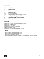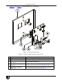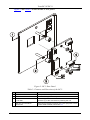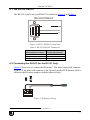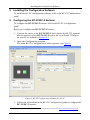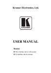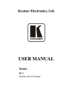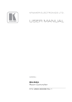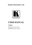
1
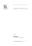
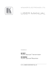
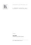
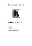
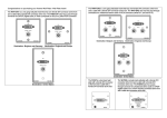
Kramer Electronics, Ltd.
USER MANUAL
Models:
RC-2C, Wall Plate / RS-232 / IR Controller
RC-2, Wall Plate / RS-232 Controller
Contents
Contents
1
2
3
4
4.1
4.2
5
6
7
Introduction
Getting Started
Overview
Your RC-2C/RC-2
The RS-232 PINOUT
Connecting the IR-OUT (for the RC-2C Only)
Installing the Configuration Software
Configuring the RC-2C/RC-2 Buttons
Technical Specifications
1
1
1
2
5
5
6
6
7
Figures
Figure 1: RC-2/RC-2C for Europe and the United States
Figure 2: RC-2C Rear Panel
Figure 3: RC-2 Rear Panel
Figure 4: RS-232 PINOUT Connection
Figure 5: IR Emitter Wiring
Figure 6: RC-SV Configuration Window for RC-2C
2
3
4
5
5
6
Tables
Table 1: Features and Functions of the RC-2C
Table 2: Features and Functions of the RC-2
Table 3: RS-232 PINOUT Connection
Table 4: Technical Specifications of the RC-2C/RC-2 Wall Plate / RS-232 Controller
3
4
5
7
i
Introduction
1
Introduction
Welcome to Kramer Electronics! Since 1981, Kramer Electronics has been
providing a world of unique, creative, and affordable solutions to the vast range
of problems that confront the video, audio, presentation, and broadcasting
professional on a daily basis. In recent years, we have redesigned and upgraded
most of our line, making the best even better! Our 1,000-plus different models
now appear in 11 groups 1 that are clearly defined by function.
Congratulations on purchasing your Kramer RC-2C Wall Plate / RS-232/ IR
Controller and/or the RC-2 Wall Plate / RS-232 Controller which are available
in European (80mm and 86mm versions) and American versions.
The package includes the following items:
• RC-2C Wall Plate / RS-232/ IR Controller or RC-2 Wall Plate / RS-232
Controller
• RC-SV Configuration Software
• This user manual 2
2
Getting Started
We recommend that you:
• Unpack the equipment carefully and save the original box and packaging
materials for possible future shipment
• Review the contents of this user manual
• Use Kramer high performance high resolution cables 3
3
Overview
The RC-2C/RC-2 is a 1 Gang 2-button controller 4 with an RS-232 port, an IR
OUT port (for the RC-2C only) and two backlit and label capable buttons. It
sends an RS-232 command—with the push of a button—to a device (such as a
projector, display or switcher) via serial control protocols.
Each button can be assigned with up to four macro sequences (each sent by the
toggle of a button) containing up to four commands each.
1 GROUP 1: Distribution Amplifiers; GROUP 2: Switchers and Matrix Switchers; GROUP 3: Control Systems; GROUP 4:
Format/Standards Converters; GROUP 5: Range Extenders and Repeaters; GROUP 6: Specialty AV Products; GROUP 7:
Scan Converters and Scalers; GROUP 8: Cables and Connectors; GROUP 9: Room Connectivity; GROUP 10: Accessories
and Rack Adapters; GROUP 11: Sierra Products
2 Download up-to-date Kramer user manuals from the Internet at: http://www.kramerelectronics.com
3 The complete list of Kramer cables is on our Web site at http://www.kramerelectronics.com
4 Available as a 1 Gang wall plate for the USA or a 1 Gang wall plate for Europe (in two sizes: 8.6cm and 8cm)
1
Your RC-2C/RC-2
4
Your RC-2C/RC-2
The RC-2C/RC-2 is available in three versions 1 (see Figure 1): one for
Belgium and Germany, one for England and Europe (except Belgium and
Germany), and one for the United States:
Destination: Belgium and Germany
Destination: England and Europe
Destination: United States
Rear Panel Labels
for the RC-2C Only
RC-2C
Figure 1: RC-2/RC-2C for Europe and the United States
1 The RC-2C front panel has the same appearance as the RC-2 panel
2
KRAMER: SIMPLE CREATIVE TECHNOLOGY
Your RC-2C/RC-2
Figure 2 and Table 1 define the RC-2C rear panel:
Figure 2: RC-2C Rear Panel
Table 1: Features and Functions of the RC-2C
#
Feature
Function
1
RC-2C Front Panel
Front panel, including two control buttons
2
PROGRAM ENABLE Switch
For technical support use only
3
GND PIN
IR OUT PIN
4
5
+12V PIN
GND PIN
RS-232 Terminal Block
Connector
Connect to an IR emitter cable
Connects (-) to the Ground
Connects (+) to the connector for powering the unit
Connect to the RS-232 connector on the A/V equipment or a
PC or other Serial Controller, see Section 4.1
3
Your RC-2C/RC-2
Figure 3 and Table 2 define the RC-2 rear panel:
Figure 3: RC-2 Rear Panel
Table 2: Features and Functions of the RC-2
#
1
2
3
4
4
Feature
RC-2 Front Panel
PROGRAM ENABLE Switch
GND PIN
+12V PIN
RS-232 Terminal Block
Connector
Function
Front panel, including two control buttons
For technical support use only
Connects (-) to the Ground
Connects (+) to the connector for powering the unit
Connect to the RS-232 connector on the A/V equipment or a PC
or other Serial Controller, see section 4.1
KRAMER: SIMPLE CREATIVE TECHNOLOGY
Your RC-2C/RC-2
4.1 The RS-232 PINOUT
The RS-232 9-pin D-sub port PINOUT is defined in Figure 4 and Table 3:
RS-232 PINOUT
9
8
7
6
5
GND
4
3
Rx
2
1
Tx
Figure 4: RS-232 PINOUT Connection
Table 3: RS-232 PINOUT Connection
Connect this PIN on the
Terminal Block Connector:
Tx
Rx
GND
To this PIN on the
9-pin D-sub Connector
PIN 2
PIN 3
PIN 5
4.2 Connecting the IR-OUT (for the RC-2C Only)
Figure 5 shows how to connect the IR emitter 1. The white striped side connects
to IR OUT, the black side connects to the Ground, and the LED Emitter Shell is
affixed to the IR sensor window with the adhesive layer.
Figure 5: IR Emitter Wiring
1 Using the Kramer 3.5mm to IR Emitter Control Cable (C-A35/IRE-10)
5
Installing the Configuration Software
5
Installing the Configuration Software
To install the RC-SV configuration software, refer to the RC-SV Configuration
guide 1.
6
Configuring the RC-2C/RC-2 Buttons
To configure the RC-2C/RC-2 buttons, refer to the RC-SV Configuration
guide1.
Before you configure the RC-2C/RC-2 buttons:
1. Connect the power to the RC-2C/RC-2 and connect the RS-232 terminal
block connector on the RC-2C/RC-2 unit to the 9-pin D-sub COM port
on your PC as defined in Section 4.1.
2. Open the Configuration program.
The main RC-SV Configuration window appears, see Figure 6.
Figure 6: RC-SV Configuration Window for RC-2C
3. Follow the instructions in the RC-SV Configuration guide to configure the
RC-2C/RC-2 buttons.
1 Download up-to-date Kramer user manuals and guides from the Internet at this URL: http://www.kramerelectronics.com
6
KRAMER: SIMPLE CREATIVE TECHNOLOGY
Technical Specifications
7
Technical Specifications
Table 4 defines the technical specifications:
1
Table 4: Technical Specifications of the RC-2C/RC-2 Wall Plate / RS-232 Controller
PORTS:
POWER SOURCE:
DIMENSIONS:
WEIGHT:
ACCESSORIES:
OPTIONS:
1 RS-232 on a terminal block connector
IR OUT on a terminal block connector (for RC-2C only)
12V DC/500mA adapter, 40mA
For the USA:
6.9cm x 1.6cm x 11.4cm (2.72" x 0.63" x 4.49", W, D, H)
For Europe:
8.6cm x 1.6cm x 8.6cm (3.39" x 0.63" x 3.39", W, D, H), the “86mm version” or
8cm x 1.6cm x 8cm (3.15" x 0.63" x 3.15", W, D, H), the “80mm version”
0.3kg (0.67lbs.) approx
RC-SV configuration software
RS-232 9-pin D-sub port to 3-pin terminal block connector cable (C-D9F/3PM-0.6)
1 Specifications are subject to change without notice
7
LIMITED WARRANTY
Kramer Electronics (hereafter Kramer) warrants this product free from defects in material and workmanship under the
following terms.
HOW LONG IS THE WARRANTY
Labor and parts are warranted for seven years from the date of the first customer purchase.
WHO IS PROTECTED?
Only the first purchase customer may enforce this warranty.
WHAT IS COVERED AND WHAT IS NOT COVERED
Except as below, this warranty covers all defects in material or workmanship in this product. The following are not covered
by the warranty:
1. Any product which is not distributed by Kramer, or which is not purchased from an authorized Kramer dealer. If you are
uncertain as to whether a dealer is authorized, please contact Kramer at one of the agents listed in the Web site
www.kramerelectronics.com.
2. Any product, on which the serial number has been defaced, modified or removed, or on which the WARRANTY VOID
IF TAMPERED sticker has been torn, reattached, removed or otherwise interfered with.
3. Damage, deterioration or malfunction resulting from:
i) Accident, misuse, abuse, neglect, fire, water, lightning or other acts of nature
ii) Product modification, or failure to follow instructions supplied with the product
iii) Repair or attempted repair by anyone not authorized by Kramer
iv) Any shipment of the product (claims must be presented to the carrier)
v) Removal or installation of the product
vi) Any other cause, which does not relate to a product defect
vii) Cartons, equipment enclosures, cables or accessories used in conjunction with the product
WHAT WE WILL PAY FOR AND WHAT WE WILL NOT PAY FOR
We will pay labor and material expenses for covered items. We will not pay for the following:
1. Removal or installations charges.
2. Costs of initial technical adjustments (set-up), including adjustment of user controls or programming. These costs are the
responsibility of the Kramer dealer from whom the product was purchased.
3. Shipping charges.
HOW YOU CAN GET WARRANTY SERVICE
1. To obtain service on you product, you must take or ship it prepaid to any authorized Kramer service center.
2. Whenever warranty service is required, the original dated invoice (or a copy) must be presented as proof of warranty
coverage, and should be included in any shipment of the product. Please also include in any mailing a contact name,
company, address, and a description of the problem(s).
3. For the name of the nearest Kramer authorized service center, consult your authorized dealer.
LIMITATION OF IMPLIED WARRANTIES
All implied warranties, including warranties of merchantability and fitness for a particular purpose, are limited in duration to
the length of this warranty.
EXCLUSION OF DAMAGES
The liability of Kramer for any effective products is limited to the repair or replacement of the product at our option. Kramer shall
not be liable for:
1. Damage to other property caused by defects in this product, damages based upon inconvenience, loss of use of the product, loss
of time, commercial loss; or:
2. Any other damages, whether incidental, consequential or otherwise. Some countries may not allow limitations on how long an
implied warranty lasts and/or do not allow the exclusion or limitation of incidental or consequential damages, so the above
limitations and exclusions may not apply to you.
This warranty gives you specific legal rights, and you may also have other rights, which vary from place to place.
NOTE: All products returned to Kramer for service must have prior approval. This may be obtained from your dealer.
This equipment has been tested to determine compliance with the requirements of:
EN-50081:
EN-50082:
CFR-47:
"Electromagnetic compatibility (EMC);
generic emission standard.
Part 1: Residential, commercial and light industry"
"Electromagnetic compatibility (EMC) generic immunity standard.
Part 1: Residential, commercial and light industry environment".
FCC* Rules and Regulations:
Part 15: “Radio frequency devices
Subpart B Unintentional radiators”
CAUTION!
Servicing the machines can only be done by an authorized Kramer technician. Any user who makes changes or
modifications to the unit without the expressed approval of the manufacturer will void user authority to operate the
equipment.
Use the supplied DC power supply to feed power to the machine.
Please use recommended interconnection cables to connect the machine to other components.
* FCC and CE approved using STP cable (for twisted pair products)
8
KRAMER: SIMPLE CREATIVE TECHNOLOGY
For the latest information on our products and a list of Kramer
distributors, visit our Web site: www.kramerelectronics.com,
where updates to this user manual may be found.
We welcome your questions, comments and feedback.
Safety Warning:
Disconnect the unit from the power supply before
opening/servicing.
Caution
Kramer Electronics, Ltd.
Web site: www.kramerelectronics.com
E-mail: [email protected]
P/N: 2900-000546 REV 2