1
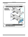
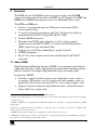
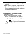
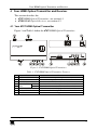
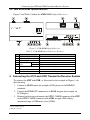
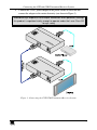
Kramer Electronics, Ltd.
USER MANUAL
Models:
670T, HDMI Optical Transmitter
670R, HDMI Optical Receiver
Contents
Contents
1
2
2.1
3
3.1
3.2
4
4.1
4.2
5
6
Introduction
Getting Started
Quick Start
Overview
About HDMI
Recommendations for Achieving the Best Performance
Your HDMI Optical Transmitter and Receiver
Your 670T HDMI Optical Transmitter
Your 670R HDMI Optical Receiver
Connecting the 670T and 670R Transmitter/Receiver System
Technical Specifications
1
1
2
3
3
4
5
5
6
6
8
Figures
Figure 1: 670T HDMI Optical Transmitter
Figure 2: 670R HDMI Optical Receiver
Figure 3: Connecting the 670T/670R Transmitter/Receiver System
5
6
7
Tables
Table 1: 670T HDMI Optical Transmitter Features
Table 2: 670R HDMI Optical Receiver Features
Table 3: Technical Specifications of the 670T and the 670R
5
6
8
i
Introduction
1 Introduction
Welcome to Kramer Electronics! Since 1981, Kramer Electronics has been
providing a world of unique, creative, and affordable solutions to the vast range
of problems that confront the video, audio, presentation, and broadcasting
professional on a daily basis. In recent years, we have redesigned and upgraded
most of our line, making the best even better! Our 1,000-plus different models
now appear in 11 groups1 that are clearly defined by function.
Congratulations on purchasing your Kramer DigiTOOLS® 670T HDMI
Optical Transmitter and/or 670R HDMI Optical Receiver which are ideal for:
Home theater, presentation and multimedia applications
Long range multimedia distribution for cinemas, stores, and
entertainment centers
Video production and broadcast facilities
Retail stores and other point-of-sale systems
The package includes the following:
670T and/or 670R
Power adapter (5V DC Input)
This user manual2
The multimode (OM3) fiber cable with SC connectors is not supplied with the
unit
2 Getting Started
We recommend that you:
Unpack the equipment carefully and save the original box and
packaging materials for possible future shipment
Review the contents of this user manual
Use Kramer high performance high resolution cables3
1 GROUP 1: Distribution Amplifiers; GROUP 2: Switchers and Matrix Switchers; GROUP 3: Control Systems; GROUP 4:
Format/Standards Converters; GROUP 5: Range Extenders and Repeaters; GROUP 6: Specialty AV Products; GROUP 7:
Scan Converters and Scalers; GROUP 8: Cables and Connectors; GROUP 9: Room Connectivity; GROUP 10: Accessories
and Rack Adapters; GROUP 11: Sierra Products
2 Download up-to-date Kramer user manuals from the Internet at this URL: http://www.kramerelectronics.com
3 The complete list of Kramer cables is on our Web site at http://www.kramerelectronics.com
1
Getting Started
2.1 Quick Start
This quick start chart summarizes the basic setup and operation steps.
2
KRAMER: SIMPLE CREATIVE TECHNOLOGY
Overview
3 Overview
The 670T converts the HDMI signal to an optical signal, and the 670R
converts the optical signal back into an HDMI signal. Together, the 670T and
670R form an HDMI transmitter/receiver over multimode fiber system.
The 670T and 670R pair:
Features a transmission range of 1700 meters (more than 5570ft)
over an optical cable
Is strictly regulated in accordance with Class 3R Laser Eye Safety in
compliance with ANSI Z136 and IEC 60825-1:2007
Includes HDMI connectors
Transmits four TMDS video channels as well as one low-speed
channel for passing HDCP, EDID, 5V source and a Hot Plug Detect
(HPD) signal over one multimode fiber
Supports up to 2.25Gbps bandwidth per graphic channel1
Is HDCP compliant
Has 5V DC power adapters and is housed in Kramer DigiTOOLS®
enclosures
3.1 About HDMI
High-Definition Multimedia Interface (HDMI) is an uncompressed all-digital2
audio/video interface, widely supported in the entertainment and home cinema
industry. It delivers the highest high-definition image and sound quality.
In particular, HDMI3:
Provides a simple4 interface between any audio/video source, such as a
set-top box, DVD player, or A/V receiver and video monitor, such as a
digital flat LCD / plasma television (DTV), over a single lengthy5 cable
Supports standard, enhanced, high-definition video, and multi-channel
digital audio6 on a single cable
1 Suitable for resolutions up to UXGA at 60Hz, and for all HD resolutions
2 Ensuring an all-digital rendering of video without the losses associated with analog interfaces and their unnecessary digitalto-analog conversions
3 HDMI, the HDMI logo and High-Definition Multimedia Interface are trademarks or registered trademarks of HDMI
licensing LLC
4 With video and multi-channel audio combined into a single cable, the cost, complexity, and confusion of multiple cables
currently used in A/V systems is reduced
5 HDMI technology has been designed to use standard copper cable construction at up to 15m
6 HDMI supports multiple audio formats, from standard stereo to multi-channel surround-sound. HDMI has the capacity to
support Dolby 5.1 audio and high-resolution audio formats
3
Overview
Transmits all ATSC HDTV standards and supports 8-channel digital
audio, with bandwidth to spare to accommodate future enhancements and
requirements
Benefits consumers by providing superior, uncompressed digital video
quality via a single cable1, and user-friendly connector
Is backward-compatible with DVI (Digital Visual Interface)
Supports two-way communication between the video source (such as a
DVD player) and the digital television, enabling new functionality such as
automatic configuration and one-button play
HDMI has the capacity to support:
Existing high-definition video formats (720p, 1080i, and 1080p/60), as
well as standard definition formats such as NTSC or PAL
3.2 Recommendations for Achieving the Best Performance
To achieve the best performance:
Connect only good quality connection cables, thus avoiding
interference, deterioration in signal quality due to poor matching,
and elevated noise-levels (often associated with low quality cables)
Avoid interference from neighboring electrical appliances and position
your 670T and 670R away from moisture, excessive sunlight and dust
Caution – No operator-serviceable parts inside unit.
Warning – Use only the Kramer Electronics input power
wall adapter that is provided with this unit2.
Warning – Disconnect power and unplug unit from wall
before installing or removing device or servicing unit.
1 HDMI provides the quality and functionality of a digital interface while also supporting uncompressed video formats in a
simple, cost-effective manner
2 For example, part number 2535-052002
4
KRAMER: SIMPLE CREATIVE TECHNOLOGY
Your HDMI Optical Transmitter and Receiver
4 Your HDMI Optical Transmitter and Receiver
This section describes the:
670T HDMI Optical Transmitter, see section 4.1
670R HDMI Optical Receiver, see section 4.2
4.1 Your 670T HDMI Optical Transmitter
Figure 1 and Table 1 define the 670T HDMI Optical Transmitter:
Figure 1: 670T HDMI Optical Transmitter
Table 1: 670T HDMI Optical Transmitter Features
#
1
2
3
4
5
6
7
8
Feature
5V DC
OPTIC CABLE Connector1
HDMI IN Connector
FIBER
CONNECTED
LEDs
SOURCE
HOT PLUG LED
VIDEO DETECT LED
ON LED
Function
+5V DC connector for powering the unit
Connect to the optical connector on the 670R
Connects to the HDMI source
Illuminates when the fiber optic cable is connected
Illuminates when a source is connected
Indicates a connected display on the receiver side
Indicates a valid video signal on the transmitter side
Illuminates when receiving power
1 With a dust cap cover
5
Connecting the 670T and 670R Transmitter/Receiver System
4.2 Your 670R HDMI Optical Receiver
Figure 2 and Table 2 define the 670R HDMI Optical Receiver:
Figure 2: 670R HDMI Optical Receiver
Table 2: 670R HDMI Optical Receiver Features
#
1
2
3
4
5
6
7
8
Feature
5V DC
OPTIC CABLE Connector1
HDMI OUT Connector
CONNECTED
FIBER
LEDs
SOURCE
HOT PLUG LED
VIDEO DETECT LED
ON LED
Function
+5V DC connector for powering the unit
Connect to the optical connector on the 670T
Connects to the HDMI acceptor
Lights when the fiber optic cable is connected
Lights when a source is connected
Indicates a connected display on the receiver side
Indicates a valid video signal on the transmitter side
Illuminates when receiving power
5 Connecting the 670T and 670R Transmitter/Receiver System
To connect the 670T and 670R, as illustrated in the example in Figure 3, do
the following:
1. Connect an HDMI source (for example a DVD player) to the HDMI IN
connector.
2. Connect the HDMI OUT connector to an HDMI acceptor (for example, an
LCD display).
3. Remove the dust caps and connect the OPTIC CABLE connector of the 670T
to the OPTIC CABLE connector of the 670R, via optic OM3 cabling2
(maximum range of 1700 meters (over 5570ft)).
1 Covered with a dust cap
2 With SC connectors
6
KRAMER: SIMPLE CREATIVE TECHNOLOGY
Connecting the 670T and 670R Transmitter/Receiver System
4. Connect the 5V DC power adapter to the power socket on each unit and
connect the adapter to the mains electricity (not shown in Figure 3).
Avoid direct eye exposure into the optic connectors when powered, although
this product is regulated strictly enough to operate under the Laser Class 3R
for eye safety
Figure 3: Connecting the 670T/670R Transmitter/Receiver System
7
Technical Specifications
6 Technical Specifications
Table 3 includes the technical specifications1.
Table 3: Technical Specifications of the 670T and the 670R
INPUTS:
OUTPUTS:
BANDWIDTH:
COMPLIANCE WITH
HDMI STANDARD:
EXTENSION LIMIT:
FIBER-OPTIC
CONNECTION:
INDICATOR LEDs:
POWER SOURCE:
DIMENSIONS:
WEIGHT:
ACCESSORIES:
OPTIONS:
670T
670R
HDMI Connector
1 optical connector
1 optical connector
HDMI Connector
Supports up to 2.25Gbps bandwidth per graphic channel
Supports HDMI 1.3, using fiber optic communication links and DDC2B
1700m (>5570 feet) for 1080p/60Hz
SC connectors for multimode (OM3) fiber cable (not supplied with the unit)
Video, source, acceptor fiber and on LEDs
5V DC, 250mA
5V DC, 230mA
12cm x 7.95cm x 2.76cm (4.7" x 3.1" x 1.08", W, D, H)
0.3kg (0.67lbs) approx. each
2 power supplies (5V/2A), 2 bracket installation kits
HDMI/HDMI male-to-male cable 2
1 Specifications are subject to change without notice
2 The complete list of Kramer cables is on our Web site at http://www.kramerelectronics.com
8
KRAMER: SIMPLE CREATIVE TECHNOLOGY
LIMITED WARRANTY
Kramer Electronics (hereafter Kramer) warrants this product free from defects in material and workmanship under the
following terms.
HOW LONG IS THE WARRANTY
Labor and parts are warranted for seven years from the date of the first customer purchase.
WHO IS PROTECTED?
Only the first purchase customer may enforce this warranty.
WHAT IS COVERED AND WHAT IS NOT COVERED
Except as below, this warranty covers all defects in material or workmanship in this product. The following are not covered
by the warranty:
1. Any product which is not distributed by Kramer, or which is not purchased from an authorized Kramer dealer. If you are
uncertain as to whether a dealer is authorized, please contact Kramer at one of the agents listed in the Web site
www.kramerelectronics.com.
2. Any product, on which the serial number has been defaced, modified or removed, or on which the WARRANTY VOID
IF TAMPERED sticker has been torn, reattached, removed or otherwise interfered with.
3. Damage, deterioration or malfunction resulting from:
i) Accident, misuse, abuse, neglect, fire, water, lightning or other acts of nature
ii) Product modification, or failure to follow instructions supplied with the product
iii) Repair or attempted repair by anyone not authorized by Kramer
iv) Any shipment of the product (claims must be presented to the carrier)
v) Removal or installation of the product
vi) Any other cause, which does not relate to a product defect
vii) Cartons, equipment enclosures, cables or accessories used in conjunction with the product
WHAT WE WILL PAY FOR AND WHAT WE WILL NOT PAY FOR
We will pay labor and material expenses for covered items. We will not pay for the following:
1. Removal or installations charges.
2. Costs of initial technical adjustments (set-up), including adjustment of user controls or programming. These costs are the
responsibility of the Kramer dealer from whom the product was purchased.
3. Shipping charges.
HOW YOU CAN GET WARRANTY SERVICE
1. To obtain service on you product, you must take or ship it prepaid to any authorized Kramer service center.
2. Whenever warranty service is required, the original dated invoice (or a copy) must be presented as proof of warranty
coverage, and should be included in any shipment of the product. Please also include in any mailing a contact name,
company, address, and a description of the problem(s).
3. For the name of the nearest Kramer authorized service center, consult your authorized dealer.
LIMITATION OF IMPLIED WARRANTIES
All implied warranties, including warranties of merchantability and fitness for a particular purpose, are limited in duration to
the length of this warranty.
EXCLUSION OF DAMAGES
The liability of Kramer for any effective products is limited to the repair or replacement of the product at our option. Kramer shall
not be liable for:
1. Damage to other property caused by defects in this product, damages based upon inconvenience, loss of use of the product, loss
of time, commercial loss; or:
2. Any other damages, whether incidental, consequential or otherwise. Some countries may not allow limitations on how long an
implied warranty lasts and/or do not allow the exclusion or limitation of incidental or consequential damages, so the above
limitations and exclusions may not apply to you.
This warranty gives you specific legal rights, and you may also have other rights, which vary from place to place.
NOTE: All products returned to Kramer for service must have prior approval. This may be obtained from your dealer.
This equipment has been tested to determine compliance with the requirements of:
EN-50081:
EN-50082:
CFR-47:
"Electromagnetic compatibility (EMC);
generic emission standard.
Part 1: Residential, commercial and light industry"
"Electromagnetic compatibility (EMC) generic immunity standard.
Part 1: Residential, commercial and light industry environment".
FCC* Rules and Regulations:
Part 15: “Radio frequency devices
Subpart B Unintentional radiators”
CAUTION!
Servicing the machines can only be done by an authorized Kramer technician. Any user who makes changes or
modifications to the unit without the expressed approval of the manufacturer will void user authority to operate the
equipment.
Use the supplied DC power supply to feed power to the machine.
Please use recommended interconnection cables to connect the machine to other components.
* FCC and CE approved using STP cable (for twisted pair products)
9
For the latest information on our products and a list of Kramer
distributors, visit our Web site: www.kramerelectronics.com,
where updates to this user manual may be found.
We welcome your questions, comments and feedback.
Safety Warning:
Disconnect the unit from the power supply before
opening/servicing.
Caution
Class 3R Laser Compliance
This product complies with “ANSI Z136” and
“IEC 60825-1:2007”.
CLASS 3R LASER PRODUCT
Kramer Electronics, Ltd.
Web site: www.kramerelectronics.com
E-mail: [email protected]
P/N: 2900-000483 REV 1