1
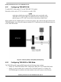
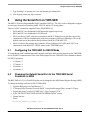
Freescale Semiconductor
Application Note
Document Number: AN4117
Rev. 0, 07/2010
Unlocking the Features for the
TWR-MPC5125-KIT
by: Maclain Lobdell
Austin, Texas
1
Introduction
The MPC5125 tower module (TWR-MPC5125) can
operate stand-alone or within the Freescale Tower
System. This application note describes how to use the
MPC5125 Tower System Kit (TWR-MPC5125-KIT)
that includes the TWR-MPC5125, TWR-SER peripheral
module, and TWR-ELEV connectors.
The MPC5125 Tower System Kit provides access to
additional features of the MPC5125 including a second
Ethernet port, RS232/RS485 connector, and a second
CAN port.
For information on all available Tower System modules
go to http://www.freescale.com/tower.
© Freescale Semiconductor, Inc., 2010. All rights reserved.
Contents
1
2
3
4
5
6
7
Introduction . . . . . . . . . . . . . . . . . . . . . . . . . . . . . . . . . . . 1
MPC5125 Tower Kit Modules . . . . . . . . . . . . . . . . . . . . . 2
2.1 TWR-MPC5125 Microprocessor Module. . . . . . . . . 2
2.2 TWR-SER Peripheral Module . . . . . . . . . . . . . . . . . 2
2.3 TWR-ELEV Connector Modules . . . . . . . . . . . . . . . 3
Assembling the System . . . . . . . . . . . . . . . . . . . . . . . . . . 3
Enabling Both Ethernet Ports on the TWR-MPC5125-KIT3
4.1 Enabling FEC1 . . . . . . . . . . . . . . . . . . . . . . . . . . . . 3
4.2 Enabling FEC2 . . . . . . . . . . . . . . . . . . . . . . . . . . . . 3
4.3 Testing Dual Ethernet Using MQX RTOS . . . . . . . . 5
Using the Serial Port on TWR-SER. . . . . . . . . . . . . . . . . 7
5.1 Configuring the TWR-SER for RS232 Mode . . . . . . 7
5.2 Changing the Default Serial Port to the TWR-SER . 7
5.3 Changing the Default Serial Port to the TWR-SER . 8
Using Both CAN Ports on the TWR-MPC5125-KIT. . . . . 8
6.1 TWR-MPC5125 Configuration Options for CAN2 . . 9
6.2 TWR-SER Configuration Options for CAN1 . . . . . . 9
6.3 Testing the CAN Interfaces Using MQX RTOS . . . . 9
Document Revision History . . . . . . . . . . . . . . . . . . . . . . . 9
MPC5125 Tower Kit Modules
2
MPC5125 Tower Kit Modules
2.1
TWR-MPC5125 Microprocessor Module
The TWR-MPC5125 features the MPC5125, a cost and power consumption optimized, industrial
networking, automotive, and human-machine interface solution. The MPC5125 provides numerous
communication peripherals at a competitive price and delivers ultra-low power without sacrificing
performance.
MPC5125 microprocessor highlights:
• e300c4 Power Architecture core running at 400 MHz
• Display interface supporting up to WXGA / 720 p, 24-bit color
• Up to two 10/100 Ethernet media access controller (MAC)
• Up to two USB 2.0 on-the-go (OTG) controller
• Up to four CAN 2.0A/B modules
• Up to two SD/SDIO expansion slots
TWR-MPC5125 Tower module features:
• 4 GB of MLC NAND Flash memory
• 256 MB of DDR2 SDRAM memory
• HDMI port with HDMI-DVI adaptor
• USB2.0 OTG host/device port
• On-board microphone and audio stereo out-jack
• 10/100 BaseT Ethernet port
• CAN 2.0 A/B port
• SD card interface
2.2
TWR-SER Peripheral Module
The TWR-SER peripheral module provides access to additional Ethernet, CAN, RS232/485, and USB
ports for designers developing with the Freescale Tower System. This peripheral module is designed to be
combined and used with compatible microprocessor modules such as the TWR-MPC5125.
TWR-SER peripheral module features:
• RS232/RS485 port
• 10/100 BaseT Ethernet port
• CAN 2.0 A/B port
• USB supporting host, device, and OTG modes (This USB connection is not supported by
TWR-MPC5125)
Unlocking the Features for the TWR-MPC5125-KIT, Rev. 0
2
Freescale Semiconductor
Assembling the System
2.3
TWR-ELEV Connector Modules
The TWR-ELEV Elevator modules are the basic building block of the Freescale Tower System. Designed
to connect microcontroller and peripheral modules, the Elevator modules provide the power regulation
circuitry and structural integrity needed for all configurations of an assembled Tower System.
TWR-ELEV connector module features:
• Four card-edge slots
• Standardized bus
• Two 80-pin connectors on the outside to support debugging or expansion
• Includes power regulation circuitry
3
Assembling the System
1. Press the Primary card edge of the TWR-MPC5125 module into any slot on the Functional
Elevator connector module.
NOTE
Take care to plug in the Primary card edge into the Functional Elevator. The
Primary card edge is labeled Primary and typically has a white stripe along
the edge. The Functional elevator is labeled Functional Elevator and
contains power circuitry at the bottom.
2. Do the same for the TWR-SER module. Be sure to match the Primary card edge with the
Functional Elevator
3. Finally, press the Dummy Elevator onto the card edges labeled Secondary. Be sure that all boards
are connected snugly.
4
Enabling Both Ethernet Ports on the
TWR-MPC5125-KIT
The MPC5125 has two integrated Fast Ethernet Controllers (FEC1 and FEC2).
4.1
Enabling FEC1
FEC1 is enabled by default and uses the Reduced Media Independent Interface (RMII) mode to
communicate to the Ethernet transceiver on the TWR-MPC5125 module itself. The Ethernet port is
accessible through the RJ45 jack on the TWR-MPC5125 module.
4.2
Enabling FEC2
FEC2 signals are multiplexed with USB1 on the MPC5125. Therefore only one of these functions can be
selected at a time. By default, the USB1 function is enabled. The TWR-MPC5125 module uses
demultiplexers to route the signals to the appropriate location depending on what is desired at the time.
The path of the signals is selected by jumper J27. See Figure 4-1 for details.
Unlocking the Features for the TWR-MPC5125-KIT, Rev. 0
Freescale Semiconductor
3
Enabling Both Ethernet Ports on the TWR-MPC5125-KIT
4.2.1
Configuring TWR-MPC5125
To enable FEC2, shunt jumper J27 on the TWR-MPC5125 module.
Remember to later remove J27 if it is desired to re-enable USB.
NOTE
At the time of publication, the Linux kernel that comes pre-loaded on the
TWR-MPC5125 requires USB1 to be enabled to boot-up. Therefore ensure
that the jumper on J27 is OFF if you desire to boot the pre-loaded Linux.
When enabled, the FEC2 RMII signals are routed to the primary edge connector that passes them to the
TWR-SER module via the Elevator connector modules. FEC2 communicates to the Ethernet transceiver
on the TWR-SER module.
Figure 4-1. Ethernet (FEC2) / USB (USB1) demultiplexing
4.2.2
Configuring TWR-SER for RMII Mode
The TWR-SER module supports RMII mode with the following jumper settings.
• Jumper J12 controls the Ethernet PHY configuration. Short pins 9-10 to enable RMII mode.
• Jumper J3 controls which clock is routed to the CLOCKIN0 signal (25 or 50 Mhz). The
CLOCKIN0 signal is available to the other modules in the tower system via the Elevator
Unlocking the Features for the TWR-MPC5125-KIT, Rev. 0
4
Freescale Semiconductor
Enabling Both Ethernet Ports on the TWR-MPC5125-KIT
•
4.2.3
connectors. On the TWR-MPC5125, this signal is required for RMII_REF_CLK and the frequency
must be 50 Mhz. Therefore, short pins 2-3 to route the 50 Mhz to CLOCKIN0.
Jumper J2 controls which clock (25 or 50 Mhz) is routed to the Ethernet PHY. Short pins 3-4 to
route the 50 Mhz clock to the Ethernet PHY.
Summary of Settings for Enabling FEC2
TWR-MPC5125:
• J27, short 1-2
TWR-SER:
• J12, short 9-10
• J3, short 2-3
• J2, short 3-4
4.3
Testing Dual Ethernet Using MQX RTOS
Both Ethernet ports can be tested using the Freescale MQX Real Time Operating System (RTOS) which
is available on the Freescale website at http://www.freescale.com/mpc5125.
Review the TWR-MPC5125 Quick Start Guide for TWR-MPC5125 (document number
MPC512CYMNQSG) and MQX RTOS Lab Tutorial (document number MPC512MQXTTRL) which are
available on the Freescale website at
http://www.freescale.com/webapp/sps/site/prod_summary.jsp?code=TWR-MPC5125-KIT.
4.3.1
Download and Install the Software
The following software is required and can be downloaded from http://www.freescale.com/mpc5125:
• Download and install CodeWarrior for MobileGT v9.2
• Download and install the CodeWarrior patch for MPC5125
• Download and install MQX 3.5.1 or later
• Download and install the MQX patch for MPC5125 (if applicable–see Note)
NOTE
A patch is required for the MQX 3.5.1 to support the MPC5125. If MQX
3.5.1 is used, then downloading and installing this patch is required.
4.3.2
Assemble the MPC5125 Tower Kit and Plug in the Cables
1. Plug in the USB cable from the host computer to the mini-usb connector next to the SD card slot.
This provides the “virtual com port” connection that the HyperTerminal accesses for
communication to the MPC5125. See the Quick Start Guide for TWR-MPC5125 for details.
2. Plug in an ethernet cable to the RJ45 Ethernet Jack on the TWR-SER.
3. Plug in an ethernet cable to the RJ45 Ethernet Jack on the TWR-MPC5125.
Unlocking the Features for the TWR-MPC5125-KIT, Rev. 0
Freescale Semiconductor
5
Enabling Both Ethernet Ports on the TWR-MPC5125-KIT
4. The two ethernet connections can be made to a network router or hub, directly to a host computer,
or directly together.
NOTE
Direct Ethernet connection between the two Ethernet ports requires a
crossover Ethernet cable. Direct Ethernet connection to a host computer
may require a crossover Ethernet cable depending on the host computer
manufacturer.
4.3.3
Launch the Software
1. Open HyperTerminal (or any terminal program of your choice) and select:
— Bits per second—115200
— Data bits—8
— Parity—None
— Stop bits—1
— Flow Control—None
Choose the COM port that the Serial-to-USB bridge enumerated as. See the Quick Start Guide for
TWR-MPC5125 for details.
2. Open CodeWarrior for MobileGT v9.2
3. C:\Program Files\Freescale\Freescale MQX 3.x\rtcs\examples\shell\cwmpc92\
shell_twrmpc5125.mcp
4. Build and execute the project using the methods described in the MPC5125 MQX RTOS Lab
document.
4.3.4
Send Commands Through the Terminal
When the software executes, the Shell> prompt will appear in the HyperTerminal window.
1. Type help for a list of all the shell commands
2. Type help ipconfig for a list of the ethernet commands
3. To initialize FEC1 issue the following command:
ipconfig 0 init
4. To initialize FEC2 issue the following command:
ipconfig 1 init
5. To acquire an IP address from the network for each port (if connected to a network) issue the
commands:
ipconfig 0 dhcp
ipconfig 1 dhcp
6. To set a static ip addresses (192.168.0.1 and 192.168.0.2 used as examples) issue the commands:
ipconfig 0 staticip 192.168.0.1 255.255.255.0
ipconfig 1 staticip 192.168.0.2 255.255.255.0
Unlocking the Features for the TWR-MPC5125-KIT, Rev. 0
6
Freescale Semiconductor
Using the Serial Port on TWR-SER
7. Type ipconfig 1 or ipconfig 0 to view the ethernet port information
8. Also try ping, telnet, ftp, tftp, or netstat
5
Using the Serial Port on TWR-SER
The MPC5125 has ten Programmable Serial Controllers (PSC0-9). The PSCs can be configured to support
several types of interfaces including UART, SPI, I2S, and AC97 among others.
There are 4 PSC connections supported on the TWR-MPC5125:
• PSC0 and PSC2 are designated for SPI and audio support respectively.
• PSC1 and PSC9 are designated for UART mode.
• PSC1 provides a UART serial port connection to the MCU Debug Port circuit that converts the
connection to USB for communication with a host computer (Serial-to-USB bridge). This is the
default serial port as described in the Quick Start Guide for TWR-MPC5125.
• PSC9 is routed to the primary edge connector. When configured for UART mode, PSC9 can
communicate with the RS232 / RS485 circuit on the TWR-SER board.
5.1
Configuring the TWR-SER for RS232 Mode
To communicate with a standard personal computer serial port, make sure the jumpers on the TWR-SER
are set for RS232 communication. This is the default option. See the TWR-SER User's Manual for details.
For RS232 operation:
• J15 shunt 1-2
• J17 shunt 1-2
• J18 shunt 1-2
• J19 shunt 1-2
5.2
Changing the Default Serial Port to the TWR-SER Serial
Connector in MQX
The BSP_DEFAULT_IO_CHANNEL define can be changed in the MQX Board Support Package (BSP).
To change the default serial port to PSC9 (TWR-SER):
1. Open the BSP project in CodeWarrior 9.2
2. C:\Program Files\Freescale\Freescale MQX 3.x\mqx\build\cwmpc92\bsp_twrmpc5125.mcp
3. Expand the group "twrmpc5125 BSP Files". Open "twrmpc5125.h".
4. In the "DEFAULT MQX INITIALIZATION DEFINITIONS" section
5. Change the line
From:
#define BSP_DEFAULT_IO_CHANNEL "ittyb:"
Unlocking the Features for the TWR-MPC5125-KIT, Rev. 0
Freescale Semiconductor
7
Using Both CAN Ports on the TWR-MPC5125-KIT
To:
#define BSP_DEFAULT_IO_CHANNEL "ittyj:"
6. Click the make icon to compile the project.
7. Now open your MQX application project and recompile. Print statements will now be sent to the
RS232 DB-9 Serial port connector on the TWR-SER module.
5.3
Changing the Default Serial Port to the TWR-SER Serial
Connector in U-Boot
See the TWR-MPC5125 Users Manual for information on re-compiling and flashing U-Boot to the board.
The CONFIG_PSC_CONSOLE define can be changed in the board header file ads5125.h.
To change the default serial port to PSC9 (TWR-SER):
1. Download U-Boot
2. Open the file ads5125.h in the \include\configs\ directory.
3. Scroll down to the Serial console configuration section.
4. Change CONFIG_PSC_CONSOLE to 9.
5. Therefore, to enable PSC9, change
From:
/*
* Serial console configuration
*/
#define CONFIG_PSC_CONSOLE 1 /* console is on PSC1 */
#if CONFIG_PSC_CONSOLE != 1
#error CONFIG_PSC_CONSOLE must be 1
#endif
To:
/*
* Serial console configuration
*/
#define CONFIG_PSC_CONSOLE 9 /* console is on PSC9 */
#if CONFIG_PSC_CONSOLE != 9
#error CONFIG_PSC_CONSOLE must be 9
#endif
6. Compile and re-flash the board using the methods provided in the TWR-MPC5125 Users Manual.
6
Using Both CAN Ports on the TWR-MPC5125-KIT
There are two CAN interfaces supported on TWR-MPC5125 (CAN1 and CAN2)
The CAN1 signals are routed to the primary edge connector that passes them to the TWR-SER module via
the Elevator connector modules. CAN1 communicates to the CAN transceiver on the TWR-SER module.
CAN2 signals are routed to the CAN transceiver on the TWR-MPC5125 module.
Unlocking the Features for the TWR-MPC5125-KIT, Rev. 0
8
Freescale Semiconductor
Document Revision History
6.1
TWR-MPC5125 Configuration Options for CAN2
Jumper J31 enables a 120 ohm termination resistance between the CANH and CANL signals.
To enable this termination, shunt J31.
6.2
TWR-SER Configuration Options for CAN1
Jumper header J5 selects the modes and signal connections for CAN1.
J5 Positions:
• 1-2 Put CAN transceiver into sleep mode
• 3-4 Connect Sleep pin to CAN pin (B43)
• 5-6 Connect RXD pin to CANRX pin (B41)
• 7-8 Connect TXD pin to CANTX pin (B42)
• 9-10 Apply 120 ohm termination resistor
For typical operation:
• Shunt positions 5-6 and 7-8 to connected the CAN signals to the connector. Shunt 9-10 if the
termination is desired.
6.3
Testing the CAN Interfaces Using MQX RTOS
To test out the CAN interfaces in MQX:
1. Launch CodeWarrior for MobileGT v9.2
2. Open and execute the mscan example project:
C:\Program Files\Freescale\Freescale MQX 3.6\mqx\examples\can\mscan\cwmpc92\
mscan_twrmpc5125.mcp
NOTE
Requires the MQX RTOS 3.6 or higher.
7
Document Revision History
Table 7-1. Document Revision History
Rev. No.
0
Substantive Change(s)
Initial release.
Unlocking the Features for the TWR-MPC5125-KIT, Rev. 0
Freescale Semiconductor
9
How to Reach Us:
Home Page:
www.freescale.com
Web Support:
http://www.freescale.com/support
USA/Europe or Locations Not Listed:
Freescale Semiconductor, Inc.
Technical Information Center, EL516
2100 East Elliot Road
Tempe, Arizona 85284
+1-800-521-6274 or +1-480-768-2130
www.freescale.com/support
Europe, Middle East, and Africa:
Freescale Halbleiter Deutschland GmbH
Technical Information Center
Schatzbogen 7
81829 Muenchen, Germany
+44 1296 380 456 (English)
+46 8 52200080 (English)
+49 89 92103 559 (German)
+33 1 69 35 48 48 (French)
www.freescale.com/support
Japan:
Freescale Semiconductor Japan Ltd.
Headquarters
ARCO Tower 15F
1-8-1, Shimo-Meguro, Meguro-ku,
Tokyo 153-0064
Japan
0120 191014 or +81 3 5437 9125
[email protected]
Asia/Pacific:
Freescale Semiconductor China Ltd.
Exchange Building 23F
No. 118 Jianguo Road
Chaoyang District
Beijing 100022
China
+86 10 5879 8000
[email protected]
For Literature Requests Only:
Freescale Semiconductor Literature Distribution Center
1-800-441-2447 or 303-675-2140
Fax: 303-675-2150
[email protected]
Document Number: AN4117
Rev. 0
07/2010
Information in this document is provided solely to enable system and software
implementers to use Freescale Semiconductor products. There are no express or
implied copyright licenses granted hereunder to design or fabricate any integrated
circuits or integrated circuits based on the information in this document.
Freescale Semiconductor reserves the right to make changes without further notice to
any products herein. Freescale Semiconductor makes no warranty, representation or
guarantee regarding the suitability of its products for any particular purpose, nor does
Freescale Semiconductor assume any liability arising out of the application or use of any
product or circuit, and specifically disclaims any and all liability, including without
limitation consequential or incidental damages. “Typical” parameters that may be
provided in Freescale Semiconductor data sheets and/or specifications can and do vary
in different applications and actual performance may vary over time. All operating
parameters, including “Typicals”, must be validated for each customer application by
customer’s technical experts. Freescale Semiconductor does not convey any license
under its patent rights nor the rights of others. Freescale Semiconductor products are
not designed, intended, or authorized for use as components in systems intended for
surgical implant into the body, or other applications intended to support or sustain life,
or for any other application in which the failure of the Freescale Semiconductor product
could create a situation where personal injury or death may occur. Should Buyer
purchase or use Freescale Semiconductor products for any such unintended or
unauthorized application, Buyer shall indemnify and hold Freescale Semiconductor and
its officers, employees, subsidiaries, affiliates, and distributors harmless against all
claims, costs, damages, and expenses, and reasonable attorney fees arising out of,
directly or indirectly, any claim of personal injury or death associated with such
unintended or unauthorized use, even if such claim alleges that Freescale
Semiconductor was negligent regarding the design or manufacture of the part.
RoHS-compliant and/or Pb-free versions of Freescale products have the functionality
and electrical characteristics as their non-RoHS-compliant and/or non-Pb-free
counterparts. For further information, see http://www.freescale.com or contact your
Freescale sales representative.
For information on Freescale’s Environmental Products program, go to
http://www.freescale.com/epp.
Freescale™ and the Freescale logo are trademarks of Freescale Semiconductor, Inc.
All other product or service names are the property of their respective owners.
© Freescale Semiconductor, Inc. 2010. All rights reserved.