1
semiconductor
TWR-MPC5125
User Manual
semiconductor
TWR-MPC5125 User Manual
Made by
www.
.com
Table of Contents
1.0 General Description
1.1 Device Placement and Functions
02
02
2.0 Hardware Design & Architecture
2.1 General Description
2.2 Physical Specifications
2.3 Debugger Interface
2.4 Physical Specifications
07
07
07
07
08
3.0 Control & Configuration
3.1 Switch Settings
3.2 Sw7 – Power On Reset
3.3 Sw1 – Boot Mode
3.4 Configuration Header Settings
09
09
09
09
10
4.0 Schematic
11
5.0 Operation
5.1 Central Processing Unit
5.2 Power supplies
5.3 Resets
5.4 Memory
12
12
12
12
13
6.0 U-boot, Linux setup
6.1 Host Computer Setup
6.2 Target Setup
6.3 Configuring U-Boot
6.4 NFS Root Development Deployment
6.5 How to boot from net_ramboot
14
14
15
16
19
19
7.0 How to build U-Boot, Kernel and device-tree
7.1 Cross-compilation settings
7.2 How to build
21
21
21
8.0 How to program NAND
8.1 Program Loader and U-boot
8.2 Program Device-tree and Kernel
8.3 Upgrade Filesystem from the U-Disk
23
23
26
26
Appendix A--Connector Pin Assignments
Appendix B--Memory Map
28
29
TWR-MPC 5125
01
semiconductor
Made by
TWR-MPC5125 User Manual
www.
.com
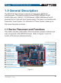
1.0 General Description
The MPC5125 Tower System is based on Freescale's MPC5125
microprocessor. The board provides on-board DDR2 SDRAM, NAND
FLASH,CAN ports, USB 2.0, 10/100 Ethernet, HDMI,USB Debug Port.All
powered from a 5 Volt wall mount power supply. This board is compatible with
Freescale's Tower System. For information of Tower System, please go to
http://www.freescale.com/tower .
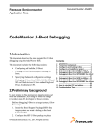
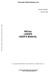
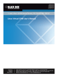
1.1 Device Placement and Functions
This section provides a description of the connectors, jumpers, switches and
main components of the MPC5125 board. Refer to Figures 1 and 2 for
location of the devices referenced below.
Primary Elevator connector 14
J4 Debug MCU Config Header 15
1 J2 JTAG Connector
2 CN1 RJ45 Ethernet Connector
U14 Debug MCU 16
J19 USB Debug port 17
3 J35 Serial Port Header
SW1 System
4 Config Switch
S / N : MP C 5 1 2 5 1 0 0 3 0 0 0 1
5 U13 USB PHY
6 Mini-AB USB Connector
7 CN3 HDMI Connector
8 U20 HMDI Transmitter
9 J27 Dual-Ethernet Jumper
SW7 Reset Swich 18
SW8 Hibemate Swich 19
J33 Depopulated
Battery Site 20
U1 MPC5125 21
SD Card Connector 22
J31 CAN Termination
Jumper 23
J34 CAN Connector 24
10 J3 On-Board Microphone (MIC)
DC 5V
11 J1 Earphone Connector
U6 DDR Memory 25
J20 DC In 26
U7 DDR Memory 27
12 U28 Audio CODEC
13 Secondary Elevator Connctor
Figure 1
TWR-MPC 5125
02
semiconductor
TWR-MPC5125 User Manual
www.
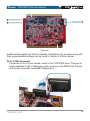
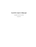
MAC:00-22-78-00-49-7A
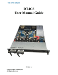
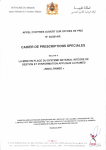
28 U10 NAND Flash Memory
Made by
29 U4 Digital Accelerometer
.com
U2 Ethernet PHY 30
Figure 2
Additional descriptions of the functionality of switches and jumpers along with
their recommended settings can be found in Section 3 of this manual.
1
J2- JTAG Connector
Connector J2 is a 16-pin header used for the COP/JTAG input. This port is
made available to aid of debugging code running on the MPC5125.The pinouts for the connector are listed in Appendix A
TWR-MPC 5125
03
semiconductor
TWR-MPC5125 User Manual
Made by
www.
.com
2
Cn1 RJ45 Ethernet Connector
Cn1 is a standard Ethernet input jack
3
J35 Serial Port Header
J35 is the serial port header with the following 2x2 header to MPC5125 pin
assignments:
PSC2_2
PSC2_3
PSC2_0
PSC2_1
4
SW1 System config switch
See switch settings. Section 3
5
U13 USB PHY
U13 is a Hi-Speed USB 2.0 ULPI transceiver
6
Mini-AB USB Connector
DOWN4 is a USB mini AB connector that is compatible with the USB 2.0
format.
CN3 HDMI Connector
CN3 is a HDMI interface
7
8
U20 HMDI Transmitter
U20 is a HDMI transmitter
9
J27 Dual-Ethernet Jumper
J27 is the dual-Ethernet jumper. Connecting a jumper across the terminals
will enable a second Ethernet connection to be made over the Primary
Elevator Connector in addition to the CN1 RJ45 Ethernet jack. Connecting
this jumper will disable the Mini-AB USB Connector.
TWR-MPC 5125
04
semiconductor
TWR-MPC5125 User Manual
Made by
www.
.com
10
J3 On-Board Microphone (MIC)
Audio input
11
J1 Earphone Connector
Audio output
12
U28 Audio CODEC
U28 is Audio CODEC
13
Secondary Elevator Connctor
Secondary Elevator Edge Connector for the Freescale TOWER system
14
Primary Elevator connector
Primary Elevator Edge Connector for the Freescale TOWER system
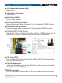
15
J4 Debug MCU Config Header
See section 3.4 for configuration header settings. A BDM module can be
connected as shown to debug code running on the Debug MCU.
Pin 1
Pin 2
Pin 3
Pin 4
Pin 5
Pin 6
16
U14 Debug MCU
U14 is Debug MCU which performs the USB to MPC5125 debug bridge
from the USB Debug Port.
17
J19 USB Debug port
J19 is the USB Debug port for the MPC5125. Power can be provided to
the system over this USB port.
18
SW7 Reset switch
SW7 is a Hardware Reset switch. Push once causes a Power on reset.
TWR-MPC 5125
05
semiconductor
TWR-MPC5125 User Manual
Made by
www.
.com
19
SW8 Hibernate Switch
SW8 is hibernate switch
Push it to wake up the system
20
J33 Depopulated Battery Site
Location to add a battery or capacitor for the Real Time Clock VBAT_RTC
power domain.Recommended capacitor is EECEN0F204RT from
Panasonic .
21
U1 MPC5125
U1 is Freescale's MPC5125 microprocessor
22
SD Card Connector
SD card interface
23
J31 CAN Termination Jumper
J31 is the CAN jumper location. Connecting a jumper across the terminals
will add termination to the CAN interface which is normally not terminated.
24
J34 CAN Connector
J34 is a CAN connector
25
U6 DDR Memory
U6 is DDR2 Memory for system running
26
J20 DC IN
J20 is the 5V DC input to the board
DC 5V
27
U7 DDR Memory
U7 is DDR2 Memory for system running
28
U10 NAND Flash Memory
U10 is a NAND Flash for uboot, Linux kernel, file system and user data
29
U4 Digital Accelerometer
U4 is a digital accelerometer
30
U2 Ethernet PHY
U2 is the Ethernet PHY with MII/RMII interface.
TWR-MPC 5125
06
semiconductor
TWR-MPC5125 User Manual
Made by
www.
.com
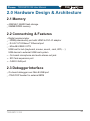
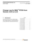
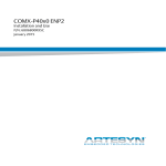
2.0 Hardware Design & Architecture
2.1 Memory
4GB MLC NAND flash storage
256MB DDR2 memory
2.2 Connectving & Features
Digital accelerometer
- HDMI(video/audio) port with HDMI to DVI--D adaptor
- RJ-45 10/100 Base T Ethernet port
- Mini-AB USB2.0 OTG
USB host to hub (keyboard, mouse, sound , card, WiFi,....)
USB device to external USB host system
- On-board microphone and audio stereo out jack
- SD Card expansion port
- CAN2.0 A/B port
2.3 Debugger Interface
On-board debugger over Mini-B USB port
JTAG/COP header for external BDM
TWR-MPC 5125
07
Made by
TWR-MPC5125 User Manual
www.
.com
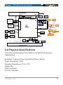
JATG
EMB_AD[0:31]
semiconductor
USB Debug Port
DDRⅡ CONTROLLER AND DATA
BUS @200MHz,(DDR2-400)
12C/1
Serial Header
LAN PHY
2.4 Physical Specifications
This section contains general information on the MPC5125's physical
characteristics
Board Size: Freescale Tower specification(59mm x 90mm)
Power Requirement: 5VDC
Operating Temperature: 0℃ to +70℃
Weight: 50g
RoHS: Compliant
FCC/CE: Compliant
TWR-MPC 5125
08
semiconductor
TWR-MPC5125 User Manual
Made by
.com
www.
3.0 Control & Configuration
This section contains general set-up information about the various jumpers,
switches on the MPC5125 board.
3.1 Switch Settings
This section provides a brief description of the functionality and recommended
settings for the switches located on the MPC5125
Refer to Figure 1 for the locations of these switches.
3.2 Sw7 – Power On Reset
Sw7 is a push button that provides a power on reset signal for the hardware
on the MPC5125.
3.3 Sw1 – Boot Mode
The mode switch provides configure the different operation of the MPC5125.
SW1 Position Reset Configuration
Signal Description
6
Boot Device Select
RST_CONF_ROMLOC0
0 = LPC Boot, 1 = NAND (NFC) boot
5
RST_CONF_BMS
4
RST_CONF_LPC_DBW0
LPC Data Port Size
3
RST_CONF_LPC_DBW1
00 = 8-bit, 01 = 16-bit, 10 = reserved, 11 = 32-bit
2
RST_CONF_LPCWA
00
1
Multiplex Mode
0 = non-multiplexed mode, 1 = multiplexed mode
TWR-MPC 5125
1
LPC Word/Byte Address Mode
0 = word address mode, 1 = byte address mode
RST_CONF_LPCMX LPC
1
Boot Mode Select
0 = boot low, 1 = boot high
1
Default
0
09
semiconductor
TWR-MPC5125 User Manual
Made by
www.
.com
3.4 Configuration Header Settings
3.4.1 J4 USB Debug Port Mode
This Jump is function select:
1-2 Short USB Debug Port
1-2 Open Serial to USB bridge
3.4.2 J4 Debug MCU mode
3-4 Short Bootloader mode
3-4 Open UART to USB bridge mode
TWR-MPC 5125
10
semiconductor
TWR-MPC5125 User Manual
Made by
www.
.com
4.0 Schematic
The schematic and basic assembly information in a portable document format
for the MPC5125 can be located on the CD with the board.
The MPC5125 design can be customized for optional flexibility and custom
interfaces so the embedded systems engineer can obtain a lower overall parts
cost using a variety of fixed and user selectable options.
These options inherently are contained in connectors, jumpers and switches
on the board.
The schematic provides guidelines for using the already installed as well as
user modifiable options available on the present design.
TWR-MPC 5125
11
semiconductor
TWR-MPC5125 User Manual
Made by
www.
.com
5.0 Operation
5.1 Central Processing Unit
The MCP5125 provides the interface to local on board resources including:
NAND FLASH memory, DDR2-SDRAM memory, MII (10/100 Fast Ethernet
Controller), RMII (10/100 Fast Ethernet Controller), I2C (EEPROM), PSC
(programmable serial controller) for RS232 and AC97 (audio), Interrupt
controller, USB 2.0 (ULPI), Display Interface Unit (DIU) Controller, SD card
interface.
See MPC5125 user manual for detail descriptions for each interface.
5.2 Power supplies
The MPC5125 accepts +5Volts only.
Power Sequencing
Power sequencing rules require that the IO voltage rail is powered before the
Core Voltages.
5.3 Resets
SW1 is a push button that provides a power on reset signal for the hardware
on the MPC5125
The MPC5125 POREST_B signal is used for the Configuration system and its
internal registers. It also is used for CPU power on reset.
5.3.1 Clocks
The main clock driver is a programmable clock synthesizer IC.
The SYS_CLK is the main processor clock (32.768 Mhz).
The 4Mhz is used by the Debug MCU.
The CLK_24.000Mhz is used by the CPU's internal USB circuitry.
The CLK_50.000Mhz is used by both the CPU's internal fast Ethernet circuitry
and the Ethernet PHY.
TWR-MPC 5125
12
semiconductor
TWR-MPC5125 User Manual
Made by
www.
.com
The RTC_CLK_32.768Khz is used by the CPU's internal XTAL_RTC drive
circuitry.
5.4 Memory
5.4.1 DDR2 SDRAM
The dedicated DDR2 memory bus is 32 bits wide, single bank, 200MHz clock
frequency, no ECC. It uses the MPC5125 DDR2 SDRAM controller and is
directly connection to the MPC5125.
5.4.2 NAND FLASH
Dedicated NAND FLASH memory is directly connected to the MPC5125 NFC
NAND flash controller.
TWR-MPC 5125
13
semiconductor
TWR-MPC5125 User Manual
Made by
www.
.com
6.0 U-boot, Linux setup (Target Deployment )
6.1 Host Computer Setup
Host computer setup is critical for your BSP to function. The host must be
running tftp and nfs servers in order for deployment to work. The following
instructions are generic. Your system may be different and the commands
should be adjusted accordingly.
The following instructions are for a Linux host computer.
1). Turn off firewall for tftp to work
$ sudo iptables –F
2). Install tftp-server on the host computer
3). Install nfs-server on the host computer
4). Create the tftpboot directory if it does not already exist
$ sudo mkdir -p /tftpboot
$ sudo chmod 777 /tftpboot
5). Copy over kernel, bootloader and devicetree for your deployment to the
/tftpboot directory
6). Tar the base filesystem to <ROOTFS_PATH> directory
$ sudo tar xpf <ROOTFS_PACKAGE>.tar –C /<ROOTFS_PATH>
7). Edit /etc/exports and add the following line
/<ROOTFS_PATH>/ *(rw,anonuid=0,anongid=0,no_subtree_check)
8). Edit /etc/xinetd.d/tftp to enable tftp like this:
{
disable = no
socket_type = dgram
TWR-MPC 5125
14
semiconductor
TWR-MPC5125 User Manual
Made by
www.
.com
protocol = udp
wait = yes
user = root
server = /usr/sbin/in.tftpd
server_args =/tftpboot
}
9). Restart the nfs and tftp servers on your host computer
$ sudo /etc/init.d/xinetd restart
$ sudo /etc/init.d/nfsserver restart
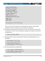
6.2 Target Setup
1). Connect your board to the network via the Ethernet port.
2). Connect your board to your host machine via a serial port.
3). Connect the board power supply.
4). Start minicom or other serial communications program of your choice.
Serial settings are 115200 baud, 8 bit chars, even parity.
5). Power on board and see the u-boot bootup message.
U-Boot 2009.03-00012-g21a175a-dirty (Jan 21 2010 - 11:03:07) MPC5125
CPU: MPC5125 rev. 1.0, Core e300c4 at 400 MHz, CSB at 200 MHz
board: mpc5125_mpu
I2C: ready
DRAM: 256 MB
NAND: 2048 MiB
In: serial
Out: serial
Err: serial
Net: FEC ETHERNET
Type run nfsboot to mount root filesystem over NFS
TWR-MPC 5125
15
semiconductor
TWR-MPC5125 User Manual
Made by
www.
.com
6.3 Configuring U-Boot
To boot the Linux kernel u-boot must have device tree support compiled in. To
verify this support is enabled, type help bootm at the u-boot prompt.
=> help bootm
bootm [addr [arg ...]]
- boot application image stored in memory
passing arguments 'arg ...'; when booting a Linux kernel, 'arg' can be the
address of an initrd image
When booting a Linux kernel which requires a flat device-tree
a third argument is required which is the address of the of the device-tree blob.
To boot that kernel without an initrd image, use a '-' for the second argument. If
you do not pass a third a bd_info struct will be passed instead
If the help message indicates that bootm takes three arguments then device
tree support is enabled. If not then it will be necessary to install a new u-boot.
See the Flashing U-Boot chapter below for details.
The factory installed u-boot has several commands predefined in the default
environment.
1). Print the existing u-boot configuration by typing “print” at the u-boot
prompt.
=> print
bootcmd=run nfsboot
bootdelay=5
baudrate=115200
loads_echo=1
preboot=echo;echo Type \"run flash_nfs\" to mount root filesystem over
NFS;echo
loadaddr=400000
u-boot_addr_r=200000
u-boot_addr=FFF00000
kernel_addr=FC040000
TWR-MPC 5125
16
semiconductor
TWR-MPC5125 User Manual
Made by
www.
.com
fdt_addr=FC2C0000
ramdisk_addr=FC300000
u-boot=ads5125/u-boot.bin
netdev=eth0
nfsargs=setenv bootargs root=/dev/nfs rw nfsroot=${serverip}:${rootpath}
ramargs=setenv bootargs root=/dev/ram rw
addip=setenv bootargs
${bootargs}ip=${ipaddr}:${serverip}:${gatewayip}:${netmask}:${hostname}:$
{netdev}:off panic=1
addtty=setenv bootargs ${bootargs}console=${consdev},${baudrate}
flash_nfs=run nfsargs addip addtty;bootm ${kernel_addr}- ${fdt_addr}
flash_self=run ramargs addip addtty;bootm
${kernel_addr}${ramdisk_addr}${fdt_addr}
net_nfs=tftp ${kernel_addr_r}${bootfile};tftp ${fdt_addr_r}${fdtfile};run
nfsargs addip addtty;bootm ${kernel_addr_r}- ${fdt_addr_r}
net_self=tftp ${kernel_addr_r}${bootfile};tftp
${ramdisk_addr_r}${ramdiskfile};tftp ${fdt_addr_r}${fdtfile};run ramargs
addip addtty;bootm ${kernel_addr_r}${ramdisk_addr_r}${fdt_addr_r}
load=tftp ${u-boot_addr_r}${u-boot}
update=protect off ${u-boot_addr}+${filesize};era ${uboot_addr}+${filesize};cp.b ${u-boot_addr_r}${u-boot_addr}${filesize}
upd=run load update
ethact=FEC ETHERNET
ethaddr=AA:BB:CC:DD:EE:FF
ramdiskfile=rootfs.ext2.gz.uboot
hostname=limeos
net_ramboot=setenv bootargs root=/dev/ram rw console=$consdev,$baudrate;tftp
${kernel_addr_r}${bootfile};tftp ${ramdisk_addr_r}${ramdiskfile};tftp
${fdt_addr_r}${fdtfile};bootm $kernel_addr_r $ramdisk_addr_r $fdt_addr_r
bootargs=root=/dev/ram rw console=ttyPSC0,115200
filesize=3000
fileaddr=400000
gatewayip=192.168.10.1
netmask=255.255.255.0
TWR-MPC 5125
17
semiconductor
TWR-MPC5125 User Manual
Made by
www.
.com
ipaddr=192.168.10.205
serverip=192.168.10.227
kernel_addr_r=3000000
fdt_addr_r=4000000
ramdisk_addr_r=5000000
rootpath=/home/tony/nfs
consdev=ttyPSC1
fdtfile=mpc5125-twr.dtb
bootfile=vmlinux-5125-twr.bin
stdin=serial
stdout=serial
stderr=serial
Environment size: 1947/131067 bytes
If your u-boot environment does not match then use the u-boot setenv
command to add or modify it to match what is printed here.
2). Tell the linux kernel which serial port to use for a console from the kernel
command line. Add a u-boot variable for setting the console on the kernel
command line.
=> setenv consoledev ttyPSC1
3). Set the board's network configuration using values appropriate for your
installation.
=> setenv ipaddr 172.27.152.21
=> setenv serverip 172.27.152.6
=> setenv netmask 255.255.0.0
=> setenv gatewayip 172.27.255.254
4). Set some pathnames needed later
=> setenv rootpath <ROOTFS-PATH>
=> setenv bootfile vmlinux-5125-twr.bin
=> setenv fdtfile mpc5125-twr.dtb
TWR-MPC 5125
18
semiconductor
TWR-MPC5125 User Manual
Made by
www.
.com
5). Save the configuration to flash
=> saveenv
6.4 NFS Root Development Deployment
During developement one typically downloads the kernel via tftp and uses nfs
for the root filesystem.
1). On the host, copy the kernel and device tree file to the tftpboot directory
2). Set nfsboot parameter
=> set nfsboot 'set bootargs ip=dhcp root=/dev/nfs rw
nfsroot=$serverip:$rootpath,proto=tcp,nolock console=$consoledev,$baudrate
$othbootargs;tftp $loadaddr $bootfile;tftp $fdtaddr $fdtfile;bootm $loadaddr $fdtaddr'
3). Now boot the board
=> run nfsboot
4). To have u-boot automatically run nfsboot at boottime set the bootcmd
variable.
=> setenv bootcmd run nfsboot
=> saveenv
6.5 How to boot from net_ramboot
1). Copy the kernel, device tree file and ram file system (rootfs.ext2.gz.ubootcommon) to tftpboot on the host computer.
Ram file system, rootfs.ext2.gz.uboot-common is generated by ltib
packages. Please refer to the LTIB help documentation.
TWR-MPC 5125
19
semiconductor
TWR-MPC5125 User Manual
Made by
www.
.com
2). Set net_ramboot parameter
=> set net_ramboot 'setenv bootargs root=/dev/ram rw
console=$consdev,$baudrate;tftp $kernel_ld_addr $kernel_name;tftp
$fdt_ld_addr $fdt_name;tftp $ramdisk_ld_addr $ramdisk_name;bootm
$kernel_ld_addr $ramdisk_ld_addr $fdt_ld_addr'
=> setenv kernel_ld_addr 0x2000000
=> setenv fdt_ld_addr 0x2800000
=> setenv ramdisk_ld_addr 0x3000000
=> setenv kernel_name vmlinux-5125-twr.bin
=> setenv fdt_name mpc5125-twr.dtb
=> setenv ramdisk_name rootfs.ext2.gz.uboot-common
=> saveenv
3). Now boot the board
=> run net_ramboot
TWR-MPC 5125
20
semiconductor
TWR-MPC5125 User Manual
Made by
www.
.com
7.0 How to build U-Boot, Kernel
and device-tree
7.1 Cross-compilation settings
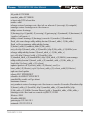
1). Install cross compiler tool chains
Tools install from the LTIB package, you can refer to the LTIB help
documentation for detailed installation instructions
2). Before cross compiling anything, you must set the environment variable:
ARCH, CROSS_COMPILE and PATH.
Set environment variables script file "ppc”
#!/bin/sh
TOOLCHAIN=/opt/freescale/usr/local/gcc-4.1.78-eglibc-2.5.78-1/powerpce300c3-linux-gnu
LTIB=/opt/freescale/ltib/usr
export ARCH=powerpc
export CROSS_COMPILE=powerpc-e300c3-linux-gnuexport PATH=$TOOLCHAIN/bin:$LTIB/bin:$PATH
$ source ppc
7.2 How to build
1). Build U-boot
$ make distclean
$ make ads5125_nand_config
$ make –j 4
2). Build Kernel
$ cp arch/powerpc/configs/mpc5125_twr_defconfig .config
$ make –j 4
TWR-MPC 5125
21
semiconductor
TWR-MPC5125 User Manual
Made by
www.
.com
Compressed kernel ulmage in the path: arch/powerpc/boot/uImage
Uncompress the kerenl uImage script file "mkvm":
#!/bin/bash
cat vmlinux.bin.gz | gunzip > vmlinux.bin
mkimage -A ppc -O Linux -T kernel -C none -a 0x0 -e 0x0 -n Linux-2.6 -d
vmlinux.bin $1
$ mkvm vmlinux-5125-twr.bin
3). Build Device-tree
Compile the DTS script file "mkdts":
#!/bin/bash
# checks for correct cmdline usage
if [ "$#" != "1" -a "$#" != "3" ]; then
echo "Usage: `basename $0` <dts-filename> [-o dtb-filename]"
exit 1
fi
DTS_FILE=$1
DTB_FILE=${DTS_FILE%%dts}dtb
if [ "${DTS_FILE##*.}" != "dts" ]; then
echo “`basename $0`: '$DTS_FILE' input file type error."
exit 1
fi
shift
if [ "$1" == "-o" ]; then
shift
DTB_FILE=$1
if [ "${DTB_FILE##*.}" != "dtb" ]; then
echo “`basename $0`: '$DTB_FILE' output file type error."
exit 1
fi
fi
./arch/powerpc/boot/dtc -I dts -O dtb -S 0x3000 -o $DTB_FILE $DTS_FILE
$ mkdts arch/powerpc/boot/dts/mpc5125-twr.dts -o mpc5125-twr.dtb
TWR-MPC 5125
22
semiconductor
TWR-MPC5125 User Manual
Made by
www.
.com
8.0 How to program NAND
8.1 Program Loader and U-boot
There are two ways, using CodeWarrior JTAG port program NAND, from
CodeWarrior for MobileGT IDE or from CodeWarrior Connection Server
command line script.
8.1.1 IDE method
What tools are needed:
· CodeWarrior IDE for MobileGT v9.2
· CodeWarrior IDE patch for MPC5125 platform
· Codewarrior USB Tap
U-Boot source code is compiled on the linux server, and Codewarrior
MobileGT v9.2 is running on windows computer. The CW-IDE create project
needed to retrieve the source of information on U-Boot directory, so customer
need to map the network drive through the linux samba service.
How to map the network drive from the windows computer:
· Configure the samba server on the linux server
· Open "My Computer" on the desktop, select Menu “Tools->Map Network
Drive"
· Like the following configuration:
Drive: Z:
Folder: \\server_ip\<U-Boot code directory on linux server>
1). Create project
. Start the CodeWarrior IDE
· Click "File->Open" and use the browse option to select u-boot in the samba
directory, CodeWarrior IDE will import u-boot and create one project.
TWR-MPC 5125
23
semiconductor
TWR-MPC5125 User Manual
Made by
www.
.com
If prompt “can't find the file libgcc2.c”, select “Continue with next file”, this
tip does not affect the previous work.
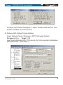
2). Settings: Edit->Default Project Settings
Target Settings Panels->Debugger->EPPC Debugger Settings:
Processor: 52xx
Target: 5125
Use Target Initialization File: 5125-twr-init.cfg, this is important initialization
DDR parameters. ( See Annex)
TWR-MPC 5125
24
semiconductor
TWR-MPC5125 User Manual
Made by
www.
.com
3). Press F5, start to run u-boot, serial port will see the u-boot bootup
message, entery command line.
4). Copy nand_spl/u-boot-spl-2k.bin and u-boot-second.bin to /tftpboot.
5). Program loader:
=> tftp 0x4000000 u-boot-spl-2k.bin
=> nand_e 0x00 0x01
=> nand_loader 0x4000000 0x00 0x800 (file size)
=> nand_r 0x2000000 0x00 0x800
=> md 0x2000000
6). Program u-boot:
=> tftp 0x4000000 u-boot-second.bin
=> nand_e 0x100 0x101
=> nand_w 0x4000000 0x100 0x40000 (file size)
=> nand_r 0x2000000 0x100 0x800
=> md 0x2000000
7). Reboot u-boot
=> reset
8.1.2 Command line method
1). Run “CodeWarrior Connection Server “C:\ Program Files\ Freescale\
CodeWarrior for MobileGT V9.2\ccs\bin\ccs.exe” .
2). Copy u-boot-second-scrip.txt and nand_spl/loader-script-5125.txt to windows
directory, example: c:\u-boot.
3). Copy 5125_init.txt to c:\u-boot ( See Annex).
4). Loader and U-boot Program.
(bin) 1 %
(bin) 2 %
(bin) 3 %
(bin) 4 %
cd /u-boot/
source 5125_init.txt
source loader-script-5125.txt
source u-boot-second-scrip.txt
TWR-MPC 5125
25
semiconductor
TWR-MPC5125 User Manual
Made by
www.
.com
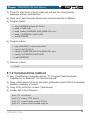
8.2 Program Device-tree and Kernel
1). Device-tree
=> setenv fdt_name mpc5125-twr.dtb
=> setenv flash_dtb 0xb00
=> tftp 0x3000000 $fdt_name
=> nand_e $flash_dtb 0xb01
=> nand_w 0x3000000 $flash_dtb 0x3000
2). Kernel
=> setenv kernel_name vmlinux-5125-twr.bin
=> setenv flash_kernel 0x300
=> tftp 0x3000000 $kernel_name
=> nand_e $flash_kernel 0xaff
=> nand_w 0x3000000 $flash_kernel 0x400000 (file size)
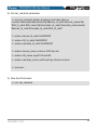
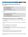
8.3 Upgrade Filesystem from a USB Disk
1. Copy the ram file system, rootfs.ext2.gz.uboot-common, to /tftpboot on the
host computer.
2. Copy the nand flash file system, <ROOTFS_PACKAGE>.tar, to a USB disk
drive.
3. Plug the USB disk drive into the target system.
4. Start ramdisk filesystem at the u-boot prompt.
=> run net_ramboot
5. Type "3" to exit the utility.
6. Install NAND rootfs by using the USB disk in ramdisk filesystem.
Type the following commands at ramdisk filesystem prompt.
TWR-MPC 5125
26
semiconductor
TWR-MPC5125 User Manual
Made by
www.
.com
$ sudo flash_eraseall /dev/mtd6
$ sudo mkdir -p /tmp/udisk /tmp/mtd
$ sudo mount -t vfat /dev/sda1 /tmp/udisk
$ sudo mount -t yaffs2 /dev/mtdblock6 /tmp/mtd
$ sudo tar xpf /tmp/udisk/<ROOTFS_PACKAGE>.tar -C /tmp/mtd
$ sudo umount /tmp/mtd
$ sudo umount /tmp/udisk
TWR-MPC 5125
27
semiconductor
TWR-MPC5125 User Manual
Made by
www.
.com
Appendix A – Connector Pin Assignments
J2 – MPC5125 JTAG (16 pin Header)
Pin No
Description
1
MPC JTAG COP TDO
2
NC
3
MPC JTAG COP TDI
4
MPC JTAG TRST
5
NC
6
3.3V DC
7
MPC JTAG TCK
8
NC
9
MPC JTAG TMS
10
NC
11
MPC SRESET
12
GND
13
HRESET
14
NC
15
MPC CKSTP OUT
16
GND
TWR-MPC 5125
28
semiconductor
Made by
TWR-MPC5125 User Manual
.com
www.
Appendix B – Memory Map
The following memory map is only an example, refer to the MPC5125 Quick
Guide for specific memory map configurations, many of these memory map
settings are user defined.
Function
Bytes
Reserved
IMMRBAR Default
setting at reset
FF40 0000
32 Bit Address
Start
End
0x8000 0000
0x803F FFFF
CS#
Size
1M Recommend
4M For future
DDR SDRAM
256MB
0x0000 0000
0x0FFF FFFF
DDR_MCSN
256MB
BOOT Space
EBC NAND
FLASH
Boot High
2048MB
0xFFF0 0000
0xFFFF FFFF
NFC_CE0_B
1MB
NAND FLASH
Upto 2GB
1MB
0x4000 0000
0x400F FFFF
1MB
SRAM
256KB
0x3000 0000
0x3001 FFFF
32KB
USB ULPI 2.0 Device
4KB
IMMR_0x3000
IMMR_3FFF
4KB
Local Configuration
Registers
1KB
IMMR_0x1 0000
IMMR_0x1 01FF
Rs232 on MPU
PSC1
IMMR_0x1 1100
IMMR_0x1 11FF
RS232 on TWR
PSC9
IMMR_0x1 1900
IMMR_0x1 19FF
IIC1
IMMR_0x0 1720
IMMR_0x0 173F
32B
IIC2
IMMR_0x0 1740
IMMR_0x0 17FF
32B
Fast Ethernet
Controller
IMMR_0x0 2800
IMMR_0x0 2FFF
256B
TWR-MPC 5125
29
Made by
www.
.com