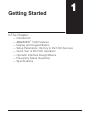
1
Getting Started $ !%# 11 ) %# &% ) Direct %&#$ ) $!' '! $$ ) %&! #%#$ % ' % ( &$$ ) & &# ( !#% ) !#% # %# $ $$ ) #"&%' $ &$% $ ) !% $ 1–2 Getting Started Getting Started Introduction The Purpose of this Manual Supplemental Manuals Technical Support This manual shows the various features and modes of the DirectVIEW 1000 (DV-1000). Your application may require the use of some of these modes, or all of them. This manual can help you decide which modes to use, and how to configure the CPU to support the DV-1000 in those modes. In the chapters on DV-1000 operational modes there are example programs to help you write the required supporting ladder program. If you are a new user, however, you may need to refer to the User Manual for the PLC you are using. How to Use DV1000 The OPĆ1500 and OPĆ1510 Operator panels may be reconfigured to exchange data with your programmable controller. The OPĆ1500 and OPĆ1510 Operator panels may be reconfigured to exchange data with your programmable controller. The DL105 User Manual (D1-USER-M), the DL205 User Manual (D2–USER–M), the DL305 User Manual (D3-USER-M; make sure you have the version covering the DL350 CPU) and the DL405 User Manual (D4–USER–M) contain related information, such as the instruction set definitions for your CPU type. In addition, the DirectSoft Quick Start Manual (QS-DSOFT-M) may also be useful. These manuals are not absolutely necessary to use the DV-1000, but might come in handy for an occasional reference. We realize that even though we strive to be the best, we may have arranged our information in such a way you cannot find what you are looking for. First, check these resources for help in locating the information: S Table of Contents – chapter and section listing of contents, in the front of this manual S Quick Guide to Contents – chapter summary listing on the next page S Appendices – reference material for key topics S Index – alphabetical listing of key words, at the end of this manual You can also check our online resources for the latest product support information: S Internet – the address of our Web site is http://www.plcdirect.com S Bulletin Board Service (BBS) – call (770)–844–4209 If you still need assistance, please call us at 800–633–0405. Our technical support group is glad to work with you in answering your questions. They are available Monday through Friday from 9:00 A.M. to 6:00 P.M. Eastern Standard Time. If you have a comment or question about any of our products, services, or manuals, please fill out and return the ‘Suggestions’ card that was shipped with this manual. Getting Started 1–3 1 2 Getting Started provides an overview of the features and provides general specifications. The importance of setup parameters and what they do are shown. “Quick Tour of DV–1000 Operation” covers the operational modes and the main features of each mode. A list of Frequently Asked Questions is located near the end of this chapter. Installation Guide explains how to select the CPU type and a communications cable, how to mount the unit in a control panel and connect it to your CPU, and how to install the example programs disk and start DirectSOFT to begin your ladder program. explains the purpose of setup parameters, how they are used, and 3 4 5 6 7 DV–1000 Setup Parameters gives example programs. Special topics include selecting the Powerup Default Mode. Message Display Mode Status Display Mode Change Preset Mode Bit Control Mode A Troubleshooting Guide B Reference Data C DV–1000 Worksheets shows how to access System Messages, including Error Messages and Fault Messages. It covers User Messages, and shows how to create your own text and numeric output and includes several example programs. tells how to view the status of CPU data types (X, Y, GX, C, SP, T, CT, S, V and P). covers the concept of changing V-memory data, the three types of titles you may attach to the values as labels, and password protection (optional) for changing preset values. An Operator’s Guide covers the keypad procedure for changing presets. discusses how to enter and exit Bit Control Mode, and how to use it in machine debug applications. Appendix A provides a list of typical problems you may encounter along with the most likely causes and solutions. Appendix B provides the setup parameter tables and a table of ASCII characters and their hex ASCII codes. Appendix C provides worksheets that you may copy and use to plan your application program. DirectVIEW 1000 The DV-1000 is a small, low-cost data access Data Access Unit unit which connects directly to all DL105, DL205 and DL405 CPUs, and to DL305 models having Overview a D3–350 CPU (it is not compatible with the other DL305 CPUs). Its main purpose is to provide access for monitoring and controlling data in the CPU, and is usually permanently installed in an operator interface, but it can also be used portably as a debugging tool. DirectVIEW (DV-1000) Getting Started Chapters The main contents of this manual are organized into the following seven chapters and Appendices A, B and C: 1–4 Getting Started Getting Started DirectVIEW 1000 Features The DirectVIEW 1000 (DV-1000) has several different modes which are accessible from its keypad. Most modes require some ladder logic in the PLC and setup parameters in V-memory, which are essential for the DV-1000 to function! This manual contains many program examples to acquaint you with all the capabilities of the DV-1000, and help you with the required setup parameters and ladder program. Some of the main features and benefits are: S S S S S S S S S DirectVIEW (DV-1000) Works with all DL105, DL205 and DL405 CPUs, and DL350 CPUs Features a 4-line by 16-character back-lit display Monitors V-memory data values Displays text and numeric data generated with your ladder program Can change preset (any V-memory) values Displays CPU-generated error messages (message log) Single cable connection to CPU Easy snap-in mounting The DV-1000 device is ULr Listed Getting Acquainted Before connecting the DV-1000 to your PLC, we’ll first study its main features. The drawing below shows a front and rear view of the unit. The 4-line by 16-character display is back-lit for viewing in various ambient lighting conditions. You can control the contrast of the LCD segments by adjusting a potentiometer accessible with a small screwdriver under the bottom of the unit. To the right of the display is a keypad featuring ten keys. These are general-purpose keys that allow you to select various operating modes, select particular data for monitoring, and to change data values. The DV-1000 is designed to fit into a rectangular cutout in the control panel of an operator interface. A retention clip on each side keeps it in place after installation. A modular jack at the rear of the unit provides an easy connection to the CPU. 4 Line by 16 Character Back-lit Display Retention Clip Keypad Phone Jack style connector Contrast Adjustment Screw Front view Rear view Getting Started Display S S M L T T O O ATUS: RUN EP: FORM PART LD TEMP. 327 F T NO. 4163 7 6 5 4 3 2 1 0 7 6 5 4 3 2 1 0 You can create your own messages by using ladder logic and special setup parameters in V-memory. The permanent numbers below the bottom edge of the display label individual bits of byte or word status displays. Keypad Cables The keypad contains ten keys, located along the right side of the DV-1000. The primary keys on the unit have a blue colored background, and are dedicated for changing the operational modes. The secondary keys have a gray colored background, and are multi-purpose keys used for cursor movements and incrementing or decrementing values in the display. There are basically two types of cables that may be used with the DV-1000. The type you will use depends mainly on the PLC type that will connect to your DV-1000. Therefore, the appropriate cable must be ordered as a separate item. See Chapter 2 for specific part number information for the proper cable. Software Examples The chapters on individual modes contain on Disk several ladder program examples. A diskette containing the files for these examples is included with this manual. The diskette symbol in the margin beside an example program indicates it is on the diskette. See the section near the end of Chapter 2, titled “Installing the Example Programs”. Change Preset Display messages Monitor Status Optional Modes Cursor Left Cursor right Decrement Value Increment Value Clear Enter OR a:\filename.prj NOTE:The DL430 CPU does not support all instructions used in the example programs. NOTE: DirectSOFT Release 2.0 programming software has a utility to configure the DV-1000; however, before using this utility it is important to understand the V-memory relationship between the DV-1000 and the PLC. See the DirectSOFT Users Manual (DA-DSOFT-M) for more information. Getting Started The DV-1000 display contains 4 lines by 16 characters, and each character is formed by a 5 x 7 LCD dot matrix. The unit’s internal processor generates an ASCII character set, and outputs menu messages associated with the keypad. 1–5 1–6 Getting Started Getting Started Display and Keypad Basics This section will familiarize you with how to use the keypad, along with the display response for each key you press. Its purpose is not to demonstrate all of the modes or display screens. The remaining chapters in this manual contain that information. NOTE: These exercises must be done in a safe learning environment. DO NOT use a CPU that is actually controlling a process, in order to avoid accidentally changing V-memory data needed by the ladder program. Clear V-memory First! The following exercises assume the DV-1000 is online with the PLC, and the CPU program, V-memory, and system parameters are clear. If your CPU has random data in these locations, then your displays will likely not match the examples. 1. Connect the communications cable from your personal computer communications port to your PLC’s programming port on the CPU. 2. Start DirectSOFT on your personal computer. 3. Select a link to go online with the CPU. 4. Save your program to a project file, if you have a program not yet saved. 5. Verify the CPU is in program mode. From the menu bar, select PLC, then PLC Modes, then Program. Then select “OK”, or press Return. 6. From the menu bar, select PLC, then Clear PLC memory, then All. Then select “OK”, or press Return. 7. From PLC menu, choose Setup, then Initialize Scratchpad. This ensures the DV-1000 setup parameters are initialized to zeros. Keypad You may recall that the keypad is color-coded, based on key functions. The blue keys are dedicated for changing the operational modes. The gray keys are multi-purpose, used for cursor movements and incrementing or decrementing values in the display. Keypad Conventions Used in this Manual This manual uses some keypad conventions. When keypad entries are required, key symbol(s) will be shown, preceded by the word “Press”. Example 1 asks you to press the Status Key followed by the Enter key. Example 2 asks you to press the Change Preset key, followed by pressing the Cursor Right Key twice. The graphic arrow points to the resulting display beside or below the key sequence. Change Preset Display messages Monitor Status Optional Modes Cursor Left Cursor Right Decrement Value Increment Value Clear Enter NOTE: When pressing multiple keys or pressing a key repetitively in a key sequence, please pause for a second between keystrokes. This allows the DV-1000 time to process each keystroke before the next keypad entry occurs. 1–7 Getting Started MSG Key (Message) Press the Change Preset Key when you need to change V-memory data. This mode requires setup parameters in V-memory. Because V-memory is cleared at this point, you will see the error message to the right, which is normal. Note the absence of a cursor in this display, indicating the cursor keys are disabled. Press the MSG key to view messages from the CPU. This mode requires setup parameters in V-memory. However, since V-memory is presently cleared the display shows a valid default “message”, consisting of all zeros. *SET UP CHECK V7620 Getting Started CHG PRE Key (Change Preset) ERROR* VALUE IN TO V7622 7 6 5 4 3 2 1 0 7 6 5 4 3 2 1 0 0 0 0 0 0 0 0 0 0 0 0 0 0 0 0 0 0 0 0 0 0 0 0 0 0 0 0 0 0 0 0 0 0 0 0 0 0 0 0 0 0 0 0 0 0 0 0 0 0 0 0 0 0 0 0 0 0 0 0 0 0 0 0 0 7 6 5 4 3 2 1 0 7 6 5 4 3 2 1 0 STAT Key (Status) CURSOR and +/– Keys Press the Status Key to view the current status of various CPU memory locations. This mode does not require setup parameters in V-memory. The default memory type displayed upon entry to Monitor Status Mode is the X input type, starting with X0. The right half of the display shows eight discrete points (one byte) per line. The particular binary pattern shown to the right is an example only. Your specific display depends on the current status of your system. The Cursor Right and Left Keys move the cursor on the top line, and the Plus (+) and Minus (–) Keys scroll the display addresses. If the display is in Status Mode as above, press the Cursor Right Key to move the cursor over to the adjacent “0”. With the cursor over the address, press the Plus (+) Key twice to increment X00 to become X20. Now press the Minus (–) Key twice to decrement the top display line back to X00. The Plus and Minus keys are also used to select data types, as well. First press the Cursor Left key to move the cursor over the top line “X”. Now press the Plus (+) Key once, and the “X”s in the display will change to “Y”s. X X X X 0 1 2 3 0 0 0 0 7 6 5 4 3 2 1 0 7 6 5 4 3 2 1 0 X X X X 2 3 4 5 0 0 0 0 7 6 5 4 3 2 1 0 7 6 5 4 3 2 1 0 Y Y Y Y 0 1 2 3 0 0 0 0 7 6 5 4 3 2 1 0 7 6 5 4 3 2 1 0 Getting Started 1–8 Getting Started OPT Key (Optional Modes) Press the Optional Modes key to gain access to three utilities which do not have dedicated keys. The display will list three items: Bit Control, Password, and Show Err/Msg. 1 2 3 OPTIO BIT CON PASSWOR SHOW ER N TROL D R/MSG 7 6 5 4 3 2 1 0 7 6 5 4 3 2 1 0 CLEAR and ENTER Keys Later we’ll use the Plus (+) and Minus (–) keys to select the item number. Next we select Bit Control mode by pressing the Enter key. The display below appears, asking us to confirm our choice. D C Y N O YO ONTR ES:P O :P U WANT BIT OL MODE? USH ENT KEY USH CLR KEY 7 6 5 4 3 2 1 0 7 6 5 4 3 2 1 0 At the moment, we will decline actually entering Bit Control mode, by pressing the Clear key. The message “Exit Bit Control Mode” confirms our choice, and then the display automatically returns to Status Display Mode after a 1 second delay. EXIT BIT CONTROL MODE 7 6 5 4 3 2 1 0 7 6 5 4 3 2 1 0 X X X X 0 1 2 3 0 0 0 0 7 6 5 4 3 2 1 0 7 6 5 4 3 2 1 0 Now that you are familiar with the keypad and display responses, you’re ready to learn the secret to successful DV-1000 programming. 1–9 Getting Started Setup Parameters, the Key to DV-1000 Success! Most DV-1000 modes require setup parameters. Refer to the figure below. These are V-memory locations in the CPU reserved for DV-1000 use. Their purpose is: Setup parameters simply tell the DV-1000 where to find its display data. Accordingly, the DV-1000 is completely lost without its setup parameters! Ladder Program V–Memory Space User Data MESSAGE DATA WRITE READ (repeatedly) Setup Parameters READ (at powerup) Typically, the ladder program writes the setup parameters to V-memory on the first CPU scan. These point to the locations of blocks of data (also written by the ladder program), which the DV-1000 needs to generate messages, preset lists, etc. By reading setup parameters after powerup, the DV-1000 is able to locate and read its operational data from the data blocks elsewhere in V–memory. The DV-1000 re-reads these data blocks continuously during operation. Programming Setup Parameters To the right is a typical program outline to support the DV-1000. On the first scan, the first rung places setup parameters in their reserved V-memory locations. The main program follows, which moves data to or from the data blocks referenced by the setup parameters as required. Chapter 3 covers setup parameters in general. Then, each chapter on an operational mode includes several setup examples for that mode. SP0 Setup Parameters Main Program END We highly recommend reading Chapter 3 on Setup Parameters thoroughly before attempting to use any mode that requires setup parameters! Getting Started Purpose of Setup Parameters 1–10 Getting Started Getting Started Quick Tour of DV-1000 Operation Status Display Mode (see Chapter 5) The Quick Tour is designed to acquaint you with the primary modes of the DV-1000. Most of the modes require ladder program support in the CPU, and consequently, some learning on your part. Also, many applications do not require the programming of all DV-1000 modes. Therefore, it is important to begin by first identifying the mode(s) most needed for your application. We recommend all new users read Chapters 1, 2, and 3 thoroughly. Then you can choose from Chapters 4 through 7 the appropriate material for your application. Status Display Mode is accessible at any time by pressing the Status Key. It does not require setup parameters. The 32-bit status display is the default upon entry to Status Display Mode, as shown below. A 64-bit status display is also selectable. 32-Bit Status X X X X 64-Bit Status 00 10 20 30 X X X X 7 6 5 4 3 2 1 0 7 6 5 4 3 2 1 0 00 20 40 60 7 6 5 4 3 2 1 0 7 6 5 4 3 2 1 0 In the left display above, the left column lists the variable type (X in this case). The next column lists the octal address. The top row displays the status of discrete inputs X00 through X07 (or, X00 to X17 on the top row of the right-most display). Data types X, Y, GX, C, SP, T, CT, S, V, and P are accessible in a circular list, as shown to the right. Cursor keys let you select the data type for viewing. Note that some CPUs feature slightly fewer data types. This mode features a “bookmark”, which records the data type and address of the V-memory location being viewed when you exit Status Display. It can be recalled during a later use of Status Display Mode later with only an extra key-stroke. Data types V and P are shown as 4-digit hexadecimal numbers. Cursor keys allow you to randomly access various address locations. If you need to change the data value(s), refer to the section on Change Preset Mode. C GX Y SP X T P CT V V V V V 2 2 2 2 1 1 1 1 0 0 0 0 0 1 2 3 S 4 4 4 4 D 3 9 5 4 4 4 2 1 8 E 0 7 6 5 4 3 2 1 0 7 6 5 4 3 2 1 0 Getting Started In Message Display Mode, display output can be from one of three different sources: System Messages (includes Fault Messages and Error Messages), and User Messages as shown. Fault Messages are generated by using the Fault Message Box in ladder logic. System Error Messages are automatically generated by the CPU upon an error event. Fault Messages and System Error Messages have display priority over User Messages. User Messages let you create numeric and text output to the entire display under ladder logic control. Only User Messages require setup parameters. Fault Messsage *PART JAM,ZONE 1 Error Message E042 NO CPU BATT User Message CO L L L N i i i V n n n EYOR e 1= e 2= e 3= S 1 4 7 P 2 5 8 EEDS 3 fpm 6 fpm 9 fpm 7 6 5 4 3 2 1 0 7 6 5 4 3 2 1 0 DL240, DL250, DL350, DL440 and DL450 CPUs can record up to 16 Error Messages and 16 Fault Messages in separate message logs as shown below. It attaches a time/date stamp to messages when they occur. These may be viewed individually with the DV-1000. Example Message Log 01 02 03 04 05 06 : 16 User Messages require ladder programming and setup parameters. Chapter 4 includes several example programs designed to show you how to add these features to your own messages: S Include text with numerical data S Blinking characters S Multiple screens with paging S Signed numbers (+/–) S Time and date stamp in message S Create bar graphs for analog data S Long messages that scroll DATE 08/10/95 08/11/95 08/11/95 08/20/95 08/30/95 08/30/95 : 08/02/95 TIME 09:35:50 08:00:43 07:15:53 17:22:48 17:22:24 17:22:24 : 9:22:16 FAULT MESSAGE PART JAMMED BIN EMPTY OVER TEMP LOW FLOW PUMP FAULT GATE STUCK : SETUP INVALID Time and Date Stamp M F T D A a i a C u m t HINE lt= B e =11 e =07 S i : / TATUS n Empty 32:57AM 05/95 7 6 5 4 3 2 1 0 7 6 5 4 3 2 1 0 Bargraph Display 1 2 3 4 7 6 5 4 3 2 1 0 7 6 5 4 3 2 1 0 Getting Started Message Display Mode (see Chapter 4) 1–11 Getting Started 1–12 Getting Started Change Preset Mode (see Chapter 6) Change Preset Mode presents data that you can view on the display and edit with the keypad. Setup parameters are required. Titles (labels) accompany the data, giving them meaning for your application. “Change Preset” just means “change V-memory data value”. Password protection is also available, if desired. TITLE FIELD My My Title Title 0000 0000 My My Title Title 0000 0000 7 6 5 4 3 2 1 0 7 6 5 4 3 2 1 0 Three types of titles are available in Change Preset Mode: S User–titled Presets allow you to My Title create your own text label of up to eight characters in length. S Pre-titled Timer labels (1 to 99) are TIMER 1 available if you have timers and can use ready-made labels. COUNTER 1 S Pre-titled Counter labels (1 to 99) are available if you have counters and can use ready-made labels. With proper setup parameters, you can establish lists of presets with text labels you create. The Change Preset Mode has built-in display scrolling capability. You can scroll to the variable name of the data you want to change, move the cursor to the data field, and change the data using the keypad. Like using thumb-wheel switches, the data in V-memory changes immediately to match the display. DATA FIELD 0000 0000 0000 USER TITLES DATA S e t P o i n t V a l u e 0 0 0 0 0 0 0 0 H i L o A l a r m A l a r m 0 0 0 0 0 0 0 0 S o a k T i m e T e m p 1 0 0 0 0 0 0 0 0 T e m p 2 G a l / M i n 0 0 0 0 0 0 0 0 Change Preset operation is depicted below. Setup parameters point to the location of title and data lists in V-memory, also defining the list length. The DV-1000 presents these as matched lists, so that a title and its corresponding data are together on the same display line. Keypad entries can request data changes, which immediately updates the data on the display and the data in V-memory. Finally, the ladder logic program uses the new data to update the machine control process. V–Memory Space User V-memory TITLES TITLES DATA My My Title Title 0000 0000 My My Title Title 0000 0000 7 6 5 4 3 2 1 0 7 6 5 4 3 2 1 0 DATA Setup Parameters Ladder Program Change data from keypad 1–13 Getting Started Bit Control Mode temporarily reassigns eight keys on the keypad for dedicated control of eight I/O bits. A Setup Parameter is required. In the drawing below, the setup parameter points to a system I/O location for either X, Y, C, or GX type I/O points. This example’s setup parameter points to a control relay location, controlling the first eight relays. The keypad switches operate as momentary, normally open switches. When ladder logic uses these bit control I/O points as inputs, keypad entries can request I/O bits to turn on as long as keys are pressed. V–Memory Space User V-memory Setup Parameters READ System I/O X Y C GX WRITE While the keypad is in Bit Control Mode, the display may be in either Message Display, Status Display, or Change Preset Mode. WARNING: Bit Control Mode is designed for debug purposes only. There is no automatic indication that normal keypad functionality has been suspended. With a simple parameter setup and ladder program, you can use Bit Control Mode to turn on an output module’s output points. In the example system to the right, the eight keys shown from the keypad have been configured to turn on control relays C0 through C7. Then the main ladder program uses these to turn on outputs Y0 through Y7. C0 C1 C2 C3 C4 C5 C6 C7 8 pt Input 8 pt 8 pt Input Output Getting Started Bit Control Mode (see Chapter 7) 1–14 Getting Started Getting Started Operator Interface Design Basics Man-Machine Interface The DV-1000 provides access to PLC data to the user while the CPU is running the RLL program, and the process or machine is running. In most applications, the DV-1000 is a permanent part of the operator interface. The operator’s panel shown in the drawing below is at the top of the control cabinet, located at the side of the machine. The operator panel contains all the dedicated operator interface devices, such as switches, gauges, control knobs, etc. The DV-1000 is one of these devices which forms the entire operator interface. In the transparent view of the control cabinet, follow the single cable from the DV–1000 to the PLC inside. From there, a wiring bundle connects it through the rear of the control cabinet to sensors and other field devices located inside the machine. The conveyor which moves the product through the machine may also be controlled by the PLC. Next we examine the interaction and flow of information between all the players in the man-machine interface. The following diagram arranges them in the order they communicate. OPERATOR DV-1000 PLC MACHINE Getting Started Action begins with the human operator, who wants to know the machine status or make an adjustment to the process. From the control panel, the operator can access data through the DV-1000, which connects to the PLC inside the control cabinet. In turn, the PLC connects to the machine or factory process through wiring to sensors, relays, solenoids, motors, and so on. The DV-1000 features several operating modes that may be used in a variety of ways. But at a basic level, it provides two types of accesses to data: monitor and control. Refer to the drawing below. OPERATOR DV-1000 PLC MACHINE Purposes of Monitoring The drawing shows the flow of information between the operator and the machine or process. The control panel communicates the status of the machine or process to the operator. Some of the kinds of information it conveys are: S Production totals S Machine setup and process status information S Quality control statistics S I/O point status for troubleshooting Use Message Display Mode (see Chapter 4) for these types of messages. For example, a diagnostic message that says “Part Jam, Zone 3” gives an operator a good idea of the nature of the problem and its location. Use Status Display Mode (see Chapter 5) to view the PLC’s I/O bit status for troubleshooting. Purposes of Control The control panel enables an operator to change the process instructions or setpoints. Some of the goals accomplished by control inputs are: S Change a process variable setpoint during runtime (such as temperature) in order to optimize the process or machine performance S Select a particular product setup from a menu S Perform machine debug by turning on specific control bits or outputs S Manually jog a machine or increment through process steps in order to to clear a part jam or fault condition S Control major machine functions (Start, Stop, etc.) *see note below* Use Change Preset Mode (see Chapter 6) to change process variables or select a product setup menu. Use Bit Control (see Chapter 7) for machine debug tasks. NOTE: For controlling major machine functions such as Start, Stop, Run, Jog, etc, we recommend using individual dedicated control devices, not the DV-1000 keypad. Getting Started Monitor and Control 1–15 1–16 Getting Started Getting Started Frequently Asked Questions NOTE: If you have general questions regarding the DV-1000 and your application, please check the following list of typical questions we receive. If you have already installed or programmed your DV-1000 and are having difficulties, refer to the Troubleshooting Guide in Appendix A at the end of this manual. If you still need assistance, please call us toll–free for technical support. Can I use the DV-1000 to change data in the PLC? Yes. There are two modes available for changing PLC data: S Change Preset Mode lets you individually edit V-memory locations as a 4-digit BCD number, from a list of either 16 or 32 data word locations, and up to 99 timer presets and 99 counter presets (depending on CPU type). S Bit Control Mode dedicates 8 of the 10 keys on the keypad for single-bit control. These operate as eight momentary, normally off pushbuttons. Is there password protection for modes that allow the operator to change PLC data? Yes, there is for Change Preset Mode. See Chapter 6 for more on this topic. How many DV-1000s can be connected to the PLC? A maximum of two DV-1000s may be directly connected to the DL240 and DL450 CPUs. See Chapter 2 for other options, and general information on this topic. Can the PLC cause the DV-1000 to always power up in a certain mode? Yes. The powerup default mode may be selected by using a particular entry in the parameter setup table. See Chapter 3 for more on this topic. Is there a way to cause the DV-1000 to stay in Bit Control Mode (or any mode that I choose)? You can set up the DV-1000 to power up in particular modes. However, if the operator presses certain keys on the keypad, this takes the DV-1000 out of its original powerup mode. Can the PLC cause the DV-1000 to change modes during normal operation (PLC run mode)? No. After establishing the powerup mode, further DV-1000 mode changes only occur upon keypad entry. When does the DV-1000 read its setup parameters from the PLC? These are read one time just after powerup, and any time a mode change is requested from the keypad. What’s the best way to enter setup parameters? We recommend imbedding the setup as a part of the ladder program. Using a SP0 contact on the rung, it only executes on the first PLC scan. See Chapter 3 for more on setup parameters. I need to display the phrase “TEMP 1”, followed by the present value of the temperature in PLC V-memory, and also to allow changing that value right on the display. Is there a way to do this? Yes. Use Change Preset Mode, with user-titled labels. Getting Started 1–17 Getting Started Can I use the DV-1000 to change timer or counter presets in the PLC? Yes. The Change Preset Mode will let you do this. See Chapter 6 for more information on this topic. Can the display show more ASCII characters than just letters of the alphabet? Yes, the DV-1000 character set includes several special symbols. See Appendix B for a complete listing of characters and symbols with their ASCII codes. Do I have to enter the ASCII codes in instruction boxes, or can I just type in the letters? Actually, you may do it either way. The LD/OUT and LDD/OUTD instructions may place ASCII codes in the text table, or the ACON instruction box can convert characters in the box to ASCII codes (see Chapter 4 for more on this topic). I need to show more than the display’s 4 lines of text. Can I scroll or swap display screens? Yes. The proper ladder logic will allow you to do this. Examples of multiple display screens and scrolling techniques may be found in Chapter 4. Can I use the DV-1000 keypad to control machine functions, like Start, Stop, Step Jog, Run, etc.? While technically possible, we strongly recommend against this type of application. Major machine control functions are best implemented with larger, dedicated switches, knobs, etc. The keys on the DV-1000 are intended primarily for various monitoring functions, or for occasionally changing V-memory Preset Values. See the next question and answer! Are there other operator interfaces available from PLC Direct? Yes. Please call our Technical Support Line (1–800–633–0405) for the latest information on other DirectLOGIC compatible products available from us or from industry affiliates. Can the PLC sense when the operator makes keypad entries? It depends. Bit Control Mode is designed for general key detection for eight of the ten available keys, which are redefined from their normal function. In the other modes, DV-1000 keypad activity cannot be detected in the PLC. Can the display indicate when the DV-1000 is in Bit Control Mode? Yes, but with some qualification. The display can be in Message Display Mode and the keypad in Bit Control Mode simultaneously (which is selectable as a powerup default mode). Ladder programming can detect keypad activity, and coordinate the message display to provide visual feedback from the keypad entry. However, the operator can leave the Message/Bit Control Modes if they desire. Can I display a numeric value in Message Mode with a leading +/– sign? Yes. An example ladder program that does this is in Chapter 4. Can I display a blinking text message during an alarm condition? Yes. An example ladder program that does this is in Chapter 4. I plan to use the DV-1000 only with a DL105 or DL205. Are there low-cost DirectSOFT programming packages available just for these models? Yes. The PC–PGM-105 and PC–PGM–205 programming packages are available, each at an attractive price for the DL105-only and DL205-only users. What is the purpose of the the adjustment screw at the bottom of the DV-1000 housing? Rotate this screw to adjust the contrast of the LCD segments on the display. 1–18 Getting Started Getting Started Specifications CPUs Supported Status Display DL130, DL230, DL240, DL250, Displays 16 or 32 point bit status DL350, DL430, DL440, and DL450 for the following data types CPUs (see Section 2, Step 5 for X, Y, GX, C, SP, T, CT, S specific communication port and Displays numeric values for cabling information) V and P data types. Cables and Connectors Change Preset Values For DL105/DL205/DL350/DL450 – DL130, DL230 and DL240 CPUs Part# DV–1000CBL 6.6ft. (2m) up to 16 user-titled values Cable with RJ12 connectors DL250, DL350 and all DL405 For DL430/DL440/DL450 – 2 CPUs up to 32 user-titled values methods: Part# D4–1000CBL, Also includes: 6.0ft. (1.85m) Cable with an RJ12 1–99 values titled as TIMERxx and a 15-pin male D-sub connector (preferred), 1–99 values titled as COUNTERxx or Part # FA-CABKIT, Use the Universal Cable Kit to attach the DV-1000CBL to the CPU port Message Display Bit Control One 4 x 16 character message Assigns 8 contiguous points to the display is available (message must DV-1000 keypad be in CPU program) Eight keys on the keypad operate Displays text and embedded as momentary normally open numeric values which update with pushbutton switches the application program Bit data types which can be Displays PLC System Error assigned are: X, Y, GX, and C Messages and Fault Message Outputs Environmental Operating Temperature . . . . . . . . . . . . . . Storage Temperature . . . . . . . . . . . . . . . . Humidity . . . . . . . . . . . . . . . . . . . . . . . . . . . Environmental Air . . . . . . . . . . . . . . . . . . . Vibration . . . . . . . . . . . . . . . . . . . . . . . . . . . Shock Resistance . . . . . . . . . . . . . . . . . . . Noise Immunity . . . . . . . . . . . . . . . . . . . . . Regulatory Agency Approvals . . . . . . . . Power . . . . . . . . . . . . . . . . . . . . . . . . . . . . . 32 to 122 °F (0 to 50 °C) –4 to 158 °F (–20 to 70 °C) 30 to 95% (non-condensing) No corrosive gases MIL STD 810C 514.2 MIL STD 810C 516.2 NEMA ICS3–304 ULr Listed 150 mA @ 5VDC obtained through PLC port Dimensions . . . . . . . . . . . . . . . . . . . . . . . . 5.12” W x 2.83” H x 1.03” D 130mm W x 72mm H x 26mm D Weight . . . . . . . . . . . . . . . . . . . . . . . . . . . . . 5.8oz. (165.7 g)