Download GV-GF Fingerprint Reader
Transcript
GV-GF Fingerprint Reader
User’s Manual
Before attempting to connect or operate this product,
please read these instructions carefully and save this manual for future use.
© 2009 GeoVision, Inc. All rights reserved.
Under the copyright laws, this manual may not be copied, in whole or in part,
without the written consent of GeoVision.
Every effort has been made to ensure that the information in this manual is
accurate. GeoVision is not responsible for printing or clerical errors.
GeoVision, Inc.
9F, No. 246, Sec. 1, Neihu Rd.,
Neihu District, Taipei, Taiwan
Tel: +886-2-8797-8377
Fax: +886-2-8797-8335
http://www.geovision.com.tw
Trademarks used in this manual: GeoVision, the GeoVision logo and GV
series products are trademarks of GeoVision, Inc. Windows and Windows XP
are registered trademarks of Microsoft Corporation.
October 2009
Contents
Regulatory Notices ...................................................................................1
Caution .....................................................................................................2
1.
2.
Introduction ........................................................................................3
1.1
Packing List.............................................................................................................4
1.2
Options ...................................................................................................................4
Connecting GV-AS Controller ............................................................5
2.1
Connecting through Wiegand Interface ..................................................................5
2.2
Connecting through RS-485 Interface ....................................................................6
3.
Fingerprint Only Mode .......................................................................7
4.
Card + Fingerprint Mode....................................................................8
4.1
Enrollment...............................................................................................................8
4.2
Deletion.................................................................................................................10
4.3
Fingerprint Reader on Service .............................................................................. 11
5.
Connecting an Alarm Device ...........................................................12
6.
Upgrading Firmware ........................................................................13
6.1
Connecting Fingerprint Reader to a Computer .....................................................13
6.2
Installing Software.................................................................................................15
Specifications .........................................................................................17
Ordering Information ..............................................................................18
Regulatory Notices
Regulatory Notices
FCC Notice
This equipment has been tested and found to comply with the limits for a Class A digital
device, pursuant to part 15 of the FCC Rules. These limits are designed to provide reasonable
protection against harmful interference when the equipment is operated in a commercial
environment.
Class A
This equipment generates, uses, and can radiate radio frequency energy and, if not installed
and used in accordance with the instruction manual, may cause harmful interference to radio
communications. Operation of this equipment in a residential area is likely to cause harmful
interference in which case the user will be required to correct the interference at their own
expense.
CE Notice
This is a Class A product. In a domestic environment, this product may cause radio
interference in which case the user may be required to take adequate measures.
RoHS Compliance
The Restriction of Hazardous Substances (RoHS) Directive is to forbid the use of hazardous
materials of production. To meet the RoHS Directive requirements, this product is made to be
RoHS compliant.
WEEE Compliance
This product is subject to the Waste Electrical and Electronic Equipment (WEEE) Directive
and made compliant with the WEEE requirements.
1
Caution
•
GV-GF1900 / 1901 / 1902 is designed only for indoor usage. Avoid exposing to sunshine
or rains.
•
To keep GV-GF1900 / 1901 / 1902 in good working condition, it is recommended to have
regular maintenance and physical cleaning of the reader.
2
2
1.
Connecting to GV-AS200 Controller
Introduction
The fingerprint reader GV-GF1900 / 1901 / 1902 can work with GV-AS Controller and
GV-ASManager to create a complete access control system. Depending on the model of the
fingerprint reader, up to two types of operation modes are supported: Card + Fingerprint and
Fingerprint Only.
Card + Fingerprint Mode:
With the fingerprint reader only, you can enroll and manage users through the supplied
Manager Enroll Card and Delete Card along with MIFARE user cards.
The fingerprint templates are stored in the user card. The user gains access by scanning both
his finger and his card. The reader compares the presented finger to that of digital template
stored in the card. If the finger is successfully authenticated, a signal is sent to momentarily
activate the door relay of the controller.
Fingerprint Only Mode:
The fingerprints are enrolled through a GV-GF1901 reader installed on the Computer running
the GV-ASManager software. The fingerprint data are distributed through GV-ASManager to
the assigned fingerprint readers installed on GV-AS Controllers for access control.
3
1.1 Packing List
If any of the items are missing or damaged, contact your dealer to arrange a replacement.
•
•
•
•
•
•
•
•
•
1.2
Fingerprint reader x 1 (with a cable of 100 cm / 3.28 feet)
Manager Enroll Card x 1
Manager Delete Card x 1
Self-Tapping Screw (M3 x 6L) x 2
Self-Tapping Screw (M4 x 15L) x 3
Plastic Screw Anchor x 3
Buzzer Hole Plate
Security Torx
User’s Manual in CD
Options
You can order the following optional accessories:
z
User Card
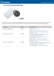
The user card is an optional item. It comes in two forms: Card and Tag. They look similar to
the following examples. You can find the serial number Fxxx,xxxxx at the bottom right corner
of the card, or at the center of the tag.
Note: Be sure that your user card has the serial number starting with the letter F; otherwise,
you cannot record the fingerprints to the user card.
z
PC Service Package
The package includes one reader mount, and one USB cable used for firmware upgrade. See
6. Upgrading Firmware later.
4
Connecting to GV-AS200 Controller
2
2.
Connecting GV-AS Controller
Depending on the model of the fingerprint reader, two types of communication links are
provided: Wiegand and RS-485.
2.1 Connecting through Wiegand Interface
The fingerprint reader is connected with an unshielded 9-wire cable of 100 cm / 3.28 feet.
Connect these 4 unshielded wires to the assigned pins on the Wiegand interface of the
GV-AS Controller: Red, Black, White and Green wires.
12V
Red
D0
Green
D1
White
GL
RL
BZ
GND
Black
GV-AS Controller
Wiegand Interface
Fingerprinter
The table below shows the wire assignments of the fingerprint reader used for Wiegand
connection.
Wire
Red
Black
White
Green
Yellow
Blue
Orange
Brown
Silver
Function
12V
GND
Data-1
Data-0
N/C
N/C
N/C
N/C
N/C
For the wiring of extending distance it is recommended to use the standard RS-485 cable (a
twisted pair of 24 AWG wires). The maximum distance of the Wiegand output cable should be
restricted to a length of 30 meters (98.43 feet).
5
2.2
Connecting through RS-485 Interface
Only GV-GF1901 and GV-GF1902 readers support RS-485 connection. Use the terminal
block on the two reader models for RS-485 connection to the GV-AS Controller.
The table below shows the pin assignments of the fingerprint reader used for RS-485
connection.
Pin
VIN
GND
T-
T+
Function
12V
GND
RS-485 -
RS-485 +
6
3
3.
Fingerprint Only Mode
Fingerprint Only Mode
The Fingerprint Only mode must work with the GV-ASManager software and the GV-GF1901
reader to enroll fingerprints. Through GV-ASManager, the fingerprint data are distributed to
GV-GF1901/1902 readers installed on GV-AS Controllers. Each fingerprint reader can save
up to 1,900 fingerprints for access control. For detailed instructions, see GV-ASManager
User’s Manual .
7
4. Card + Fingerprint Mode
4.1 Enrollment
The user’s fingerprints are stored in the user card and each user card can store up to 2
fingerprints. The user must gain access by scanning both the user card and the finger.
Specifications
•
Have access by scanning both the user card and finger.
•
Fingerprint templates are stored in the user card.
Cards Required for Enrollment
•
Manager Enroll Card
•
User Card
Enrollment Procedures
Step 1:
In the standby mode, the light is blue on. Present
the Manager Enroll Card. The light starts blinking
green.
Step 2:
Present the User Card till the light blinks blue.
Or present the Manager Enroll Card to exit the
enroll mode.
8
4
Card + Fingerprint Mode
Step 3:
With the light blinking blue, scan your fingerprint till
beep. Withdraw your finger. The light turns green
and then blinks blue.
Step 4:
Scan the same fingerprint again till beep, and
withdraw your finger. The light again turns green
and then blinks green.
Note: It is required to scan the same fingerprint
twice to complete the enrollment.
Step 5:
Repeat Steps 3 and 4 to scan the second
fingerprint if needed. The same user card can store
up to 2 fingerprints.
Step 6:
Present the User Card to record fingerprints till
beep. The light turns green and then steady blue.
Then you can use the Card Plus Fingerprint on the
fingerprint reader.
Note:
1. You will need the corresponding user card when deleting an individual user. Once you
lose the user card, you cannot delete its related user from the reader.
2. The new fingerprints enrolled will replace the existing enrolled fingerprints.
9
4.2 Deletion
Card data will be deleted from the reader and fingerprint templates will be erased from the
user card.
Cards Required for Deletion
•
Manager Delete Card
•
User Card
Deletion Procedures
Step 1:
In the standby mode, the light is blue on.
Present the Manager Delete Card. The
light starts blinking red.
Step 2:
With the light blinking red, present the
User Card. The light starts blinking green.
Present the User Card again to delete all
fingerprints stored in the card.
When the deletion is complete, the light
turns green and then steady blue.
10
4
Card + Fingerprint Mode
4.3 Fingerprint Reader on Service
After you connect the fingerprint reader to the controller, present the user card. The light on
the reader will start blinking blue. Then scan your finger to gain access.
1. If the presented fingerprint matches any record in the card, the light will turn from blue to
green. Access signal will be passed to the controller.
2. If the presented fingerprint does NOT match the record in the card, the light will turn from
steady blue to blinking red with beeps for three times. Then the light will come back to a
steady blue. The reader will not pass access signal to the controller.
11
5.
Connecting an Alarm Device
For the user of GV-GF1901 and GV-GF1902, you can connect one output device like sirens
to the reader for warning when the access is granted.
The example below illustrates the connection of an output device to the fingerprint reader.
Connect (+) point on the output device to COM on the fingerprint reader, connect the (-)
points of the output device and the external power supply together, and connect the (+) point
on the external power supply to NO or NC on the fingerprint reader based on the state of the
output device.
12
6
6.
Upgrading Firmware
Upgrading Firmware
For the user of GV-GF1901 and GV-GF1902, you can upgrade the firmware to the new
version. Firmware upgrade is done through the AutoISP software, which are available on the
software CD. The AutoISP software will detect the current version of your fingerprint reader
and then automatically upgrade it to the new version.
6.1 Connecting Fingerprint Reader to a Computer
You need to connect the fingerprint reader to a computer for firmware upgrade. For this
connection, one of these optional accessories is required: a USB cable (see PC Service
Package, 1.2 Options), GV-HUB or GV-COM.
Using the USB Cable
Using the USB cable which is included in the optional PC Service Package, connect the
fingerprint reader to a computer as illustrated below.
13
Using the GV-HUB or GV-COM
First connect the fingerprint reader to a computer through a GV-COM or GV-HUB, which
provides the RS-485 to RS-232 function. Then you need to power on the fingerprint reader by
connecting the 12V and GND wires from the GV-AS controller to the fingerprint reader. The
diagram below illustrates the connection among fingerprint reader, GV-COM / GV-HUB and a
computer.
14
6
Upgrading Firmware
6.2 Installing Software
To upgrade the firmware for GV-GF1901 and GV-GF1902, you need to install the AutoISP
software from the software CD to the dedicated computer. To install firmware upgrade
software, follow the steps below:
1.
Insert the software CD to the computer. It will run automatically and the following window
pops up.
Figure 6-1
2.
Select Install Firmware upgrade utility to install the AutoISP. After finishing the
installation, you can find the AutoISP from the Windows All Programs.
3.
Click AutoISP. This dialog box appears.
Figure 6-2
15
4.
Wait for the AutoISP detecting the COM port that the fingerprint reader is connected to
and automatically upgrading the firmware.
5.
When the AutoISP automatically finishes firmware upgrading, the current version
number shown in the dialog box will match the file version number. Click
dialog box.
Figure 6-3
16
to close the
Specifications
Specifications
GV-GF1900
GV-GF1901
GV-GF1902
Model
Indoor use only
Application
Communication
Wiegand 26
Interface
Wiegand 26,
Wiegand 26,
RS-485
RS-485
Sensor
Capacitive
Capacitive
Optical
Sensing Area
16 x 12 mm
18 x 13 mm
20 x 17 mm
(H x W)
0.63 x 0.47 (in)
0.71 x 0.51 (in)
0.79 x 0.67 (in)
Output
None
1 Port
1 Port
(240V, 2.5A)
(240V, 2.5A)
Fingerprint Only
Fingerprint Only
Fingerprint + Card
Fingerprint + Card
Operation Mode
Fingerprint + Card
Number of
1,900
Fingerprints
ISO14443A, MIFARE Class
Card Type
13.56 MHz
RF Frequency
50 mm
RF Distance
DC 7.5V~12V, Max 250mA
DC Power
Operating
0 ~ 65°C / 32 ~ 149°F
Temperature
10%~90%
Humidity
Dimension
130 x 54 x 43 (mm)
(H x W x D)
5.12 x 2.13 x 1.69 (in)
130 x 54 x 38 (mm)
5.12 x 2.13 x 1.50 (in)
17
Ordering Information
GV-GF1900
81-MF190-001
GV-GF1901
81-MF191-001
GV-GF1902
81-MF192-001
User Card
81-MA135-1F1
Tag
81-MK135-1F1
PC Service Package
E70-GFING-001
18


