1
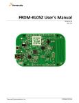
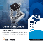
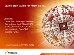
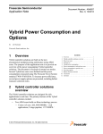
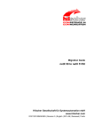
Quick Start Guide TWR-VF65GS10 For Vybrid Controller Solutions Based on ARM® Cortex®-A5 and Cortex-M4 Processors with the DS-5 Toolchain TOWER SYSTEM Quick Start Guide Get to Know the TWR-VF65GS10 Dual Quad SPI K20 JTAG Header UART Selection Primary Connector Power/OpenSDA Micro-USB Vybrid JTAG Header Reset 38-pin Mictor Trace Debug Dual USB Accelerometer External NPN Ballast LEDs Micro SD Secondary Connector General-Purpose TWRPI Plug-In DDR3 Boot Config Reset Configuration Line Drivers Pushbuttons Front Side of TWR-VF65GS10 Module TWR-VF65GS10 Freescale Tower System The TWR-VF65GS10 module is a part of the Freescale Tower System, a modular development platform that enables rapid prototyping and tool re-use through reconfigurable hardware. Elevate your design to the next level and begin constructing your Tower System today. TOWER SYSTEM Get to Know the TWR-VF65GS10 K20 OpenSDA Device Battery Receptacle (VBAT) NAND Flash Potentiometer Back Side of TWR-VF65GS10 Module 3 Quick Start Guide TWR-VF65GS10 Features •Vybrid MVF61NS151CMK50 controller (dual-core Cortex-A5 at 500 MHz + Cortex-M4 at 167 MHz, 1.5 MB SRAM, dual Ethernet, dual USB, advanced security) • Kinetis K20DX128VFM5 MCU-based OpenSDA circuit • 1 Gb x 16 (128 MB) DDR3 in 96 FBGA package • 2 Gb x 16 (256 MB) NAND flash • Two 128 MB (16 MB) quad I/O serial flash • Dual USB with on-chip PHY • Interfaces to TWR-LCD-RGB graphical LCD module • Four user-controlled status LEDs • Three mechanical push buttons for user input and one for reset • Potentiometer and three-axis digital accelerometer • Micro SD card slot • Independent battery-operated power supply for real-time clock and tamper detection module 4 TOWER SYSTEM Step-by-Step Installation Instructions This Quick Start Guide details how to set up the TWR-VF65GS10 module and run some demo projects on the device. 1 Download Software and Tools Download installation software and documentation under “Jump Start Your Design” at freescale.com/TWR-VF65GS10. 2 Configure the Hardware • Assemble your Tower System development platform per the instructions found in the TWR-ELEV module package, unless the board will be used standalone. • Insert the dual-headed USB-A side of the provided USB cable into the PC and insert the micro-B end into the OpenSDA USB port (J3) on the TWR-VF65GS10 module. Allow the PC to automatically configure the USB drivers if needed. 5 Quick Start Guide Step-by-Step Installation Instructions 3 Locate and Install CDC Device Drivers • The module will enumerate as a composite “Mass Storage and Serial CDC Device.” The drivers for the CDC functionality can be found on the enumerated drive (for example: F:\TWR-VF65GS). • Go to that drive to find the CDC drivers and install them. 4 Set up Serial Communication • A USB-to-serial bridge is supported through the USB CDC functionality. The serial port number is viewable in the Device Manager (right click, My Computer>Properties>Device Manager>Port Settings). This allows for serial communication between the Tower module and a terminal program running on the PC via the USB connection. • Setup a terminal program to use this COM port with the following settings: 115200 baud, eight data bits, no parity, one stop bit. Alternatively, you may use the TWR-SER or TWR-SER2 serial module for serial communication. See the “Introduction to the Vybrid Tower System Module” video clip at freescale.com/TWR-VF65GS10 for more details. 6 TOWER SYSTEM 5 Tilt the Board • After the TWR-VF65GS10 module powers up, the U-Boot bootloader will load the out-of-box demo from the SD card. The Cortex-A5 core runs the Linux® operating system and uses the Open SDA USB-to-serial bridge. The Cortex-M4 core runs the Freescale MQX™ RTOS and uses the TWRSER or TWR-SER2 serial module for serial communication. Both operating systems operate independently of each other on their respective cores, but can communicate via software APIs and shared memory. • Tilt the module to see different LEDs light up—the accelerometer data is being read by MQX on the M4 core and transferred to Linux on the A5 core. You will also see Linux output on the OpenSDA serial connection set up in Step 3. 6 Explore the Features • Follow the “Introduction to the Vybrid Tower System Module” video clip at freescale.com/TWR-VF65GS10 to further explore the features and capabilities of the out-of-box demo. 7 Start Debugging • To start debugging with DS-5, the OpenSDA firmware needs to be updated with the CMSIS-DAP application. For more detail, please refer to the “Jump Start Your Design” documentation located at freescale.com/TWR-VF65GS10 7 Quick Start Guide TWR-VF65GS10 Jumper Options The following is a list of all jumper options on the TWR-VF65GS10. The default settings are shown in bold. Jumper Option Setting 1-2 VBAT tied to main Vybrid 3.3 V (VCC_3V3_MCU) J1 Vybrid VBAT power source - SecureRTC, 32 kHz XOSC, Tamper, and Monitors 2-3 VBAT tied to Coin Cell VCC_3V3_MCU main Vybrid 3.3 V supply (VDD33 pins) ON P3V3 from on-board 3.3 V regulator tied directly to VCC_3V3_MCU OFF Current-measuring device installed instead of jumper OFF Pin 11 & 13 of JTAG connector floating ON Pin 11 & 13 of JTAG connecter tied to 5 V ON EXT_WM0_TAMPER_IN tied to EXT_WM0_TAMPER_OUT OFF EXT_WM0_TAMPER_IN open; EXT_WM0_TAMPER_OUT open J4 J6 J7 8 Description JTAG 5 V supply Tamper loopback J13 Accelerometer interrupt J18 3.3 V from Vybrid board to Tower system (applicable only when Elevator not powered with 5 V) ON MCU PTB9 pin tied to INT1 of accelerometer OFF Accelerometer Interrupt input untied ON P3V3 tied to P3V3_ELEV OFF Board and Tower System 3.3 V power rails untied TOWER SYSTEM (continued from previous page) Jumper J19 J20 J21 J22 Pins 1 to 10 J23 Option Setting P5V comes from USB Micro-B connector J3 (only option when “OpenSDA” operates) 2-3 P5V comes from Peripheral USB OTG Micro-B J8 1-2 Self-powered - USB0_VBUS tied to P5V 2-3 Bus-powered - USB0_VBUS tied to VBUS of Peripheral USB OTG Micro-B J8 ON USB1_VBUS tied to VBUS of Host USB Type-A J12 OFF USB1 PHY unpowered Onboard 5 V source Power source for Vybrid USB0 PHY Power source for Vybrid USB1 PHY Boot configuration ON/INSTALLED-1, OFF-0 1 2 3 4 5 2 1 4 3 6 5 8 7 10 9 SCI1_TX and SCI2_TX select Description 1-2 12_345 Switch Settings Detail 10_000 QuadSPI Boot 10_110 SD Card Boot 10_001 NAND Boot 01_xxx UART/USB Boot 00_xxx Boot From Fuses 1-2 SCI1_TX connected to ELEV_UART1_TX 1-3 SCI1_TX connected to OpenSDA_UART_RX 2-4 SCI2_TX connected to ELEV_UART1_TX 3-4 SCI2_TX connected to OpenSDA_UART_RX 9 Quick Start Guide TWR-VF65GS10 Jumper Settings (continued from previous page) Jumper J23 continued J25 R164, R165 R21 R175 to R181 10 Option Setting Description 7-8 SCI1_RX connected to ELEV_UART1_RX 7-9 SCI1_RX connected to OpenSDA_UART_TX 8-10 SCI2_RX connected to ELEV_UART1_RX 9-10 SCI2_RX connected to OpenSDA_UART_TX ON P5V tied to P5V_ELEV OFF Board and Tower System 5 V power rails untied USB0 multiplexer selection A Connected to Peripheral USB OTG Micro-B connector J8 B Connected to Tower System elevator Optional Ethernet MII interface A RMII CLK B MII0 TXCLK Optional Ethernet MII interface None RMII Interfaces used 0-Ohm MII0 Interface used SCI1_RX and SCI2_RX select Elevator 5 V supply R182 Optional Ethernet MII interface SH10 Vybrid SDRAM controller power A SAI RX BCLK B MII0 RXCLK Shorted Cut Power pins tied directly to onboard 1.5 V source Current measuring device connected across TOWER SYSTEM 11 Quick Start Guide Visit freescale.com/TWR-VF65GS10 for information on the TWR-VF65GS10, including: • TWR-VF65GS10 user manual • TWR-VF65GS10 “Introduction to the Vybrid Tower System Module” video clip • TWR-VF65GS10 schematics • Vybrid family fact sheets • Tower System fact sheet Support Visit freescale.com/support for a list of phone numbers within your region. Warranty One (1) year limited warranty. Please visit us at freescale.com/warranty for complete warranty information. For more information, visit freescale.com/Tower or freescale.com/Vybrid Join the online Tower community at towergeeks.org Freescale, the Freescale logo and Kinetis are trademarks of Freescale Semiconductor, Inc., Reg. U.S. Pat. & Tm. Off. Vybrid and Tower are trademarks of Freescale Semiconductor, Inc. All other product or service names are the property of their respective owners. ARM and Cortex are registered trademarks of ARM Limited (or its subsidiaries) in the EU and/or elsewhere. All rights reserved. © 2013, 2014 Freescale Semiconductor, Inc. Doc Number: TWRVF65GS10QSG REV 2 Agile Number: 926-27442 Rev D