1
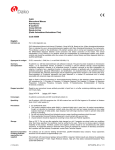
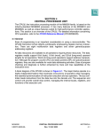
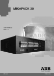
Freescale Semiconductor
Application Note
Document Number: AN4807
Rev. 0, 10/2013
Vybrid Power Consumption and
Options
by
Jiri Kotzian
Freescale Semiconductor, Inc.
1
Overview
Vybrid controller solutions are built on the new
asymmetrical multiprocessing architecture using ARM
cores. The purpose of this application note is to provide an
overview of the power consumption Vybrid controller
solutions. The document is focused on normal run modes.
Several Vybrid use cases were defined and the power
consumptions measured using The Freescale Tower System
module (TWR-VF65GS10). To increase power efficiency,
several power supply options are presented, including ballast
transistor selection notes.
2
Vybrid controller solutions
overview
The Vybrid controller solutions are designed for rich
applications in real time. The primary features of the Vybrid
controller solutions include:
• Two ARM cores build on 40nm technology process
— Cortex-A5 core: 266, 400-500MHz – rich
applications; 8 stage pipeline; 1.57 DMIPS /
© 2013 Freescale Semiconductor, Inc. All rights reserved.
1.
2.
3.
4.
5.
6.
7.
8.
9.
10.
11.
Contents
Overview . . . . . . . . . . . . . . . . . . . . . . . . . . . . . . . . . . . 1
Vybrid controller solutions overview . . . . . . . . . . . . . 1
Power use cases . . . . . . . . . . . . . . . . . . . . . . . . . . . . . 2
Working set . . . . . . . . . . . . . . . . . . . . . . . . . . . . . . . . . 2
Vybrid power consumption . . . . . . . . . . . . . . . . . . . . . 5
Power consumption in selected use cases . . . . . . . . . . 6
Power consumption in special cases . . . . . . . . . . . . . . 7
Powering options . . . . . . . . . . . . . . . . . . . . . . . . . . . . 9
Ballast transistor selection . . . . . . . . . . . . . . . . . . . . 17
Conclusion . . . . . . . . . . . . . . . . . . . . . . . . . . . . . . . . 19
Literature . . . . . . . . . . . . . . . . . . . . . . . . . . . . . . . . . . 19
Power use cases
•
MHz; ARM or Thumb mode (32- or 16 bit instructions)
— Cortex-M4 core: 133-166MHz – Real time; 3 stage pipeline; 1.25 DMIPS /MHz; Thumb mode
only (16 bit instructions only - smaller code size)
— DMA, Semaphores, Security, TrustZone, interconnected by NIC
Large set of peripherals including Ethernet, USB, SD, CAN, QuadSPI, SCI, I2C, display drivers
For more detailed information about the Vybrid controller solutions and power modes, see the Vybrid
Reference Manual (VYBRIDRM) and the corresponding datasheet on freescale.com.
3
Power use cases
The power consumption strongly depends on the application. The power requirements of your application
should be estimated referencing the following use cases.
Baremetal is the use case with the basic program running on each core. Each core controls 2 LEDs in the
infinite loop:
• Dual Core CA5 399MHz / CM4 133MHz
• VybridSC - 2LEDs each core, for CM4, for CA5, LEDs On, 100ms, LEDs Off, 100ms, SRAM,
• Configuration: TWR-VF65GS10 + TWR-ELEV + TWR-SER2
Linux use case runs Timesys LinuxLink on the primary core and playing video in WQVGA resolution:
• Single core CA5 399MHz
• All clock gates enabled, playing mp4 video in resolution 320x240
• Configuration: TWR-VF65GS10 + TWR-ELEV + TWR-SER2 + TWR-LCD-RGB
Out of the box demo (OOBE) use case runs Timesys LinuxLink on the primary core and MQX RTOS on
the secondary core:
• Dual Core CA5 399MHz / CM4 133MHz
• CM4 uses SCI2 (TWR-SER), KnightRider LEDs demo on start, welcome picture on start,
accelerometer, potentiometer, WaterFall LEDs demo, simple web server (TWR-SER2 - future)
• CA5 uses SCI1 (OpenSDA), Display QT application (TWR-LCD-RGB ), video play, WebGL web
server
• CA5 and CM4 use MMC protocol for data exchange
• Configuration: TWR-VF65GS10 + TWR-ELEV + TWR-SER2 + TWR-LCD-RGB
Reset state use case is the complementary use case for getting power consumption in the reset state,
especially TWR-LCD display background current and TWR-SER2 current:
• Configuration 1: TWR-VF65GS10 + TWR-ELEV + TWR-SER2
• Configuration 2: TWR-VF65GS10 + TWR-ELEV + TWR-SER2 + TWR-LCD-RGB
4
Working set
Defined use cases were run and tested on a prepared workstation.
Vybrid Power Consumption and Options, Rev. 0
2
Freescale Semiconductor
Working set
Figure 1. Current measuring workstation
The workstation is comprised of four precise multimeters, a power supply unit, a universal multimeter, and
an oscilloscope. Current measurement units are synchronized using the external trigger input and the start
button for measuring simultaneously. The oscilloscope is used to check the clock frequency using Vybrid
clock-out pins.
The Freescale Tower System was used in the following configurations:
• TWR-VF65GS10 Main control module with Vybrid SoC
• TWR-ELEV Elevator module: primary and secondary elevator module
• TWR-LCD-RGB: color display module with touch sense 480 x 272 pixels
• TWR-SER2: Dual Ethernet communication module with RS232 (USB), CAN and RS485
Four different measuring points were assessed. They are defined in the Table 1.
Table 1. Measuring points
Power supply 5V
Whole tower system power supply 5V
TFR-VF65 name
I_P3V3
3.3 V power supply for whole tower system - bulk power source takes current from 5V
J18
I_3V3_MCU
3.3V power supply for MCU: IO, Internal LDO, External LDO =
including I_1V2_Core
J4
I_1V5_SDRAM
1.5V power supply for Vybrid part of SDRAM circuits - not including
SDRAM (DDR3) external memory
J10
I_1V2 Core
1.2V power supply for the core and analog front end AFE - use
internal LDO with external transistor - supplied from 3V3 MCU
Q1 pin 3 - manually
added jumper
header
Vybrid Power Consumption and Options, Rev. 0
Freescale Semiconductor
3
Working set
Figure 2. The current measuring points on Vybrid tower module
Vybrid Power Consumption and Options, Rev. 0
4
Freescale Semiconductor
Vybrid power consumption
Measuring points are captured in the schematic in Table 2. The red circles mark the measuring points.
Three measuring points used on-module jumper headers. The core current1 measuring point required a
slight modification of the circuit. Additional jumper header was added on the module.
Power rail I_3V3_MCU is used for the entire Vybrid SoC power supply, including the core. To get current
for Vybrid input/output pins we need to subtract the core current using the following formula:
NOTE
The formula is used in measurements of current in selected use cases.
5
Vybrid power consumption
The current consumption strongly depends on the application, the run mode, and on the temperature. The
Vybrid SoC includes numerous gates. The application defines how many gates will be used during the run
of the application. The datasheet’s maximal current refers to the currents taken by component when all
gates are utilized. The real application does not use 100% of gates. As demonstrated by the real measured
currents, gate utilization is usually less than 50%, so current consumption is usually less than the half of
datasheet values.
5.1
Datasheet values
Datasheet values are presented in Table 2. See the latest revision of the Vybrid datasheet for the most
current values, available on freescale.com.
Table 2. Vybrid current data from datasheet (rev. 4)
Vybrid Power Mode
Functional Description
Current (25°C)
RUN
All functionality available
700mA
WAIT
Core halted
600mA
LPRUN
24MHz operation. PLL bypassed
100mA
ULPRUN
32kHz or 128kHz operation, PLL off
50mA
STOP
Lowest Power mode with all power retained, RAM retention
10mA
LPSTOP3
64kB SRAM retention, I/O states held, ADCs/DACs optionally power
gated. RTC functional, Wake-up on Interrupt.
100uA
LPSTOP2
16kB SRAM retention, I/O states held, ADCs/DACs optionally power
gated. RTC functional, Wake-up on Interrupt.
50uA
LPSTOP1
I/O states held, ADCs/DACs optionally power gated. RTC functional,
Wake-up on Interrupt.
25uA
The parameters of silicon components depend on the temperature. In integrated circuits in particular, the
main dependencies are leakage currents. From an external point of view, the component current
consumption increases with the operating temperature.
1. Note that core current means the whole platform current which includes CA5, CM4, NIC, SRAM, etc.
Vybrid Power Consumption and Options, Rev. 0
Freescale Semiconductor
5
Power consumption in selected use cases
Estimated currents:
• For 25°C and 100% utilization it is up to 700mA.
• For 85°C and 100% utilization it is up to 850mA.
6
Power consumption in selected use cases
The following sections contain the results of measuring power supply currents in defined measuring
points, in selected use cases. All data are measured in normal run mode at room temperature (22-25°C).
6.1
Baremetal
Dual Core - VybridSC - 2 LEDs drive by each core, LEDs On 100ms, LEDs Off 100ms, SRAM location,
399MHz / 133MHz.
Table 3. Baremetal results
Power Domain
Nominal Power supply [V]
Current [mA]
Power [mW]
Core
1.2
157
193
SDRAM (Vybrid)
1.5
7
10
External
3.3
24
73
Vybrid overall
—
—
277
Tower system overall
5V
410
2050
6.2
Linux
Single core - all clock gates enabled, playing mp4 video in resolution 320x240 (TWR-LCD-RGB),
SDRAM location.
Table 4. Linux results
Power Domain
Nominal Power supply [V]
Current [mA]
Power [mW]
Core 399 MHz
1.2
266
327
SDRAM (Vybrid)
1.5
120
173
External
3.3
31
94
Vybrid overall
—
—
594
Tower system overall
5V
840
4200
Single core - all clock gates enabled, playing mp4 video in resolution 320x240 (TWR-LCD-RGB),
SDRAM location.
Table 5. Linux results
Power Domain
Core 198MHz
Nominal Power supply [V]
1.2
Current [mA]
183
Power [mW]
225
Vybrid Power Consumption and Options, Rev. 0
6
Freescale Semiconductor
Power consumption in special cases
Table 5. Linux results (continued)
SDRAM (Vybrid)
1.5
119
173
External
3.3
33
100
Vybrid overall
—
—
496
Tower system overall
5V
760
3800
6.3
OOBE demo
OOBE demo - Dual core on LINUX and MQX, QT, playing mp4 video in resolution 320x240
(TWR-LCD-RGB), MCC, WebGL, SDRAM / SRAM location.
Table 6. OOBE results
Nominal
Power supply [V]
Power Domain
Power
[mW]
Current [mA]
Core
1.2
289
355
SDRAM (Vybrid)
1.5
126
180
External
3.3
30
97
Vybrid overall
—
—
632
Tower system overall
5V
860
4300
6.4
Reset
Reset state - VybridSC, TWR-SER2 powered, TWR-LCD-RGB backlight (optional).
Table 7. Reset results
Nominal
Power supply [V]
Power Domain
Power
[mW]
Current [mA]
Core
1.2
13
16
SDRAM (Vybrid)
1.5
7
10
External
3.3
5
15
Vybrid overall
—
—
41
Tower system overall
5V
370
1850
Tower system overall (TWR-LCD-RGB)
5V
490
2450
7
Power consumption in special cases
The user application requires data memory. In the case of using external memory the application takes
more energy, as shown in the following table.
Vybrid Power Consumption and Options, Rev. 0
Freescale Semiconductor
7
Power consumption in special cases
7.1
Consumption depending on Code placement
Hello world application – print on serial channel.
Table 8. Consumption depending on code placement
Code placement
Nominal
Voltage [V]
Current [mA]
Power [mW]
Note
SRAM
1.2
148
182
SRAM current included
SDRAM (DDR3)
1.5 + 3.3
184 + 106 = 290
227 +159 = 386
DDR3 memory consumption not
included ~100mA / 1.5V
QSPI
1.2
136
167
QSPI memory consumption not
included ~50mA / 3.3V
7.2
Consumption depending on frequency
The operating frequency has significant influence on the final power consumption. Higher frequency
applications require more current.
Dual core Hello world application – print on serial channel and LEDs blinking.
Table 9. Consumption depending on frequency
Cores Frequency
CA5/CM4 [MHz]
Vybrid Current 1.2V rail [mA]
Power [mW]
399/133
156
192
450/150
172
212
500/166
187
230
7.3
Idd current versus temperature
Smaller technology processes involve a higher dependency on temperature, mainly due to leakage
currents. Measured values are captured in the following table.
Temperature is measured 5mm from SoC package on the Vybrid tower module.
Hello world application – print on serial channel.
Table 10. Temperature and Idd current
Temperature [°C]
Idd 1.2V [mA]
25
260
65
310
70
320
80
343
85
355
Vybrid Power Consumption and Options, Rev. 0
8
Freescale Semiconductor
Powering options
8
Powering options
LDO or DC/DC converters can be used. The correct selection depends on the maximal current taken from
a selected branch or rail.
8.1
Vybrid power rails
Vybrid requires up to four different voltages; the first two are essential:
• 3.3V for input/output pins and internal LDOs
• 1.2V for core power supply and video ADC analog front end
• 1.2V/1.5V for SDRAM interface (optional)
• 5V for USB (optional)
Two power rails must be supplied for normal run. The first power rail is 1.2V for the core. This rail is also
used for Video ADC analog front end. The second rail used is 3.3V voltage level for input/output pins and
to power Vybrid internal LDOs. The 1.2V supply voltage can be stabilized using the internal LDO
regulators (LPREG) for low power modes or with the internal LDO control with the external ballast
transistor (HPREG) for the normal run mode. If SDRAM (LP-DDR2 or DDR3) is used, an additional
power supply is needed. The voltage level depends on the type of memory used. In the case of LP-DDR2,
it is 1.2V. In the case of DDR3, it is 1.5V. If USB is used in host mode, a 5V voltage level is needed to
provide VBUS. 5V is usually power source for 3.3V and 1.5V DC/DC converters.
The block scheme of the internal Vybrid power configuration and the recommended external circuit are
shown in the Figure 3. The block scheme is taken from the Vybrid datasheet.
Vybrid Power Consumption and Options, Rev. 0
Freescale Semiconductor
9
Powering options
Figure 3. Vybrid power supply block diagram
8.2
Power options
The recommended circuit presented in Figure 3 (and used on the Vybrid tower module) is not very
efficient. Particularly in the case of low power applications, better powering options can be defined. The
powering options are presented in following paragraphs. Note that the efficiency of DC/DC converters
(usually 90-95%) is not taken into account.
All power options for the Vybrid controller solutions include:
• External ballast transistor powered from VDD (default)
• External ballast transistor powered from VSDRAM
Vybrid Power Consumption and Options, Rev. 0
10
Freescale Semiconductor
Powering options
•
External DC/DC converter
8.3
External ballast transistor powered from VDD (default)
The recommended circuit for general purpose application uses an external ballast transistor, which is
powered from 3.3V to create a 1.2V power supply. This solution simple and suitable for a wide range of
applications, but is very low-efficiency. Its simplicity is demonstrated in particular in the case that
SDRAM memory is not used. The solution is also used on the Vybrid Freescale Tower module.
Figure 4. External ballast transistor powered from VDD
The block scheme of the power supply solution using the external ballast transistor powered from VDD
on 3.3V voltage level is captured in Figure 4.
8.3.1
Power efficiency considerations
In this power option, the Vybrid SoC uses an internal control LDO circuit with external ballast transistor
for normal run power mode. This solution creates 1.2V power supply voltage for the core and Video ADC
analog front end using the external ballast transistor. As shown in Figure 3 and Figure 4, the transistor is
powered from 3.3V power rail.
In OOBE demo use case core current is 289mA.
Vybrid Power Consumption and Options, Rev. 0
Freescale Semiconductor
11
Powering options
The core power is:
Total power on LDO with external ballast transistor is:
The power efficiency in this case is:
Such low power efficiency is due to the voltage drop on the transistor:
as compared to 1.2V on the core. Moreover, the efficiency of the 3.3V DC/DC converter and 1.5V LDO
are not included.
This solution is suitable when:
• a simple application with low current requirements is used;
• SDRAM is not used;
• simplicity is preferred;
• the thermal power loss on ballast transistor and the size of the transistor package in not an issue.
This solution is recommended especially for simple baremetal and test applications.
8.4
External ballast transistor powered from VSDRAM
The ballast transistor can be powered from a lower voltage level than 3.3V. This power option significantly
increases power efficiency.
Vybrid Power Consumption and Options, Rev. 0
12
Freescale Semiconductor
Powering options
Figure 5. External ballast transistor powered from VSDRAM
The block scheme of power supply solution using external ballast transistor powered from VSDRAM on 1.5
voltage level is captured in Figure 5.
The main difference from the previous power option is that the ballast transistor, which supplies power to
the core, is powered from 1.5V voltage level power rail. A 1.5V power supply is used for powering
SDRAM and it uses the switched mode power supply (DC/DC).
In the OOBE demo use case, the core current is 289mA. In this case:
The core power is:
Total power on LDO with external ballast transistor is:
The power efficiency it this case is:
Vybrid Power Consumption and Options, Rev. 0
Freescale Semiconductor
13
Powering options
Such power efficiency is due to the voltage drop on the transistor:
as compared to 2.1V in the previous power option. Note than the efficiency of 3.3V DC/DC converter and
of 1.5V DC/DC converter is not taken into account.
This solution is suitable when:
• applications with medium currents used;
• SDRAM is used;
• the thermal power loss on ballast transistor and the size of the transistor package is an issue.
This solution is recommended especially for Linux applications.
8.5
External DC/DC converter
This power option increases the power efficiency to maximum level. The final efficiency depends only on
the switched mode power supply (DC/DC) efficiency.
This option uses a 1.2V switched mode power supply. The problem is that it is not possible to directly
connect the external 1.2V power supply to Vybrid VDD12 input. The reason is that when Vybrid SoC goes
into low power stop mode, it disables LDO with external ballast transistor (HPREG) and it starts using
internal LDOs. (See Figure 3.) Its output is connected to the VDD12 pin. It is not possible to feed VDD12
from an external power supply in this mode.
The solution is to start the application with external ballast transistor and before high current consumption
switch to the external 1.2V switched mode power supply. It has to be done from the user application by
the additional control pin. Any GPIO pin can be used for this purpose.
Vybrid Power Consumption and Options, Rev. 0
14
Freescale Semiconductor
Powering options
%&'
!"#$
Figure 6. External DC/DC converter
The block scheme of the power supply solution using external DC/DC converter power from 5V voltage
level is captured in Figure 6. This solution is convenient for DDR3 usage. When no DDR3 is used, it is
sufficient to power the ballast transistor from the 3V3 rail until the core is powered from 1.2V DC/DC
converter.
This solution requires special additional steps when powering up and when powering down into low power
stop modes. Correct timing and higher filtering capacities are needed.
Power up sequence:
1. Reset.
2. Core is powered from Internal LDO.
3. Start LDO with external ballast transistor.
4. Switch to power from DC/DC converter using GPIO pin (the Enable pin in Figure 6).
a) Enable DC/DC.
b) Open left FET transistor and start supplying from 1.2V DC/DC converter.
c) Close right FET transistor to stop feeding from external ballast transistor.
Vybrid Power Consumption and Options, Rev. 0
Freescale Semiconductor
15
Powering options
5. Run the extensive part of the code, which requires more current.
Low power stop mode sequence:
1. Stop extensive part of the code.
2. Switch to power from external ballast transistor using GPIO pin.
a) Open right FET transistor to start feeding from external ballast transistor.
b) Close left FET transistor to stop supplying from 1.2 DC/DC converter.
c) Disable DC/DC.
3. LDO with external ballast transistor is used.
4. Jump in to low power stop mode.
5. Core is powered from internal LDO.
8.6
Power source timing requirements
HPREG with external ballast transistor is enabled during the reset sequence. Normally 3.3V is used and
this voltage is tested during the start by internal logic.
Figure 7. Vybrid Reset/Boot sequence waveform
Yellow RESET_B; Pink EXTAL; Blue 1V2; Green BCTRL
Vybrid Power Consumption and Options, Rev. 0
16
Freescale Semiconductor
Ballast transistor selection
The complete Vybrid Reset/Boot sequence waveform is in Figure 7 and it is executed following steps:
• Power On.
• POR (400-500us)
— Start—falling edge of RESET_B.
— Wait for supply ramp 100us.
— Internal LDOs (HPREG, LPREG) are enabled (1.2V ramp in the picture).
— Wait for VREG to stabilize.
— RESET sequence (fuse read, memory repair, etc.).
— End—rising edge of RESET_B (trigger yellow triangle).
• BootROM code (5-6ms)
— Start.
— Enable external Oscillator.
— Wait for external clock to stabilize (default 3ms in rev 1.1, can be set by fuses).
— Enable PLL, switch to PPL clock (edge on BTRL signal due to increase current demand).
— Image selection, image validation, etc.
— End.
• User code
If an additional DC/DC converter is used, no check of DC/DC converter voltage level is performed within
the Vybrid BootROM code. Ensure that the power supply voltage used for powering the external ballast
transistor is present and stable before the power supply is switched from low power LDO (LPREG) to
LDO with external ballast transistor (HPREG), which is 100us after the start of POR.
9
Ballast transistor selection
Selection of right ballast transistor sets several requirements captured in following points:
• Maximal current requirement: Despite the datasheet maximal values of the core current, the
maximal current strongly depends on the application and the environment temperature. From
700mA/25C to 850mA/85C. Select the transistor according to your application and the required
current.
• hFE /BCTRL requirement: BCTRL pin current must be less than 20mA. Required hFE can be
computed for maximal required current and maximal base current, which is 20mA. Minimal hFE
is 42.5, computed as 850mA / 20mA. Preferred hFE is 150 and more. Ensure that BCTRL voltage
is less than VDDREG – 0.5V due to limited output voltage swing of the BCTRL output circuit. For
example, if VDDREG = 3.0V, then BCTRL should not exceed 2.5V.
• Transistor total power dissipation requirement: Depends on maximal current and power supply
voltage level. If low current is used it is not necessary to use 15W DPAC package which is used on
the Vybrid Tower module. The transistor package size strongly depends on total power dissipation.
• Collector-Emitter saturation voltage requirement: Must be less than the difference between power
supply voltage and core voltage on maximal used current.
• Unity current gain Frequency requirement: More than 50MHz.
Vybrid Power Consumption and Options, Rev. 0
Freescale Semiconductor
17
Ballast transistor selection
9.1
Ballast transistor examples
There exist many suitable transistors which can be used as the reference. Two examples were tested and
measured. The first of them was on Semiconductor NJD2873T4 transistor, the default transistor on
TWR-VF65GS10. The second transistor is much smaller. NXP PBSS4021NT is suitable for smaller
currents and power dissipation.
On Semiconductor NJD2873T4 datasheet data (Currently used on TWR-VF65GS10):
• 50V, 2A, NPN
• hFE = 120-360/500mA
• UCE sat for 500mA 100C: 90mV; for 1000mA 100C: 160mV
• 15W on DPAC
NXP PBSS4021NT datasheet data:
• 20 V, 4.3A, NPN, low VCEsat
• hFE = 550/500mA (typical)
• UCE sat for 500mA 100C: 28mV; for 1000mA 100C: 50mV
• 390 mW, 660 mW, 1100 mW on SOT23 (depends on PCB)
9.2
Measured data
Both transistors were measured at three different collector currents and three power supply voltages levels.
Table 11. IC = 260mA (Linux use case with Video play were used)
Transistor
NJD2873T4
PBSS4021NT
VC [V]
3.32
1.50
1.35
3.32
1.50
1.35
VE [V]
1.21
1.21
1.21
1.21
1.21
1.21
VB [V]
1.83
1.91
1.93
1.73
1.85
1.85
IB [mA]
1.16
1.28
2.00
0.3
0.36
0.49
Table 12. IC = 620mA (additional 3.3 load on 1.2V, external power supply)
Transistor
NJD2873T4
PBSS4021NT
VC [V]
1.5
1.35
1.5
1.35
IB [mA]
4.3
13.8
0.97
1.31
Table 13. IC = 810mA (additional 2.2 load on 1.2V, external power supply)
Transistor
NJD2873T4
PBSS4021NT
Vybrid Power Consumption and Options, Rev. 0
18
Freescale Semiconductor
Conclusion
Table 13. IC = 810mA (additional 2.2 load on 1.2V, external power supply)
VC [V]
1.5
1.35
1.5
1.35
IB [mA]
6.5
>20/stopped
1.32
1.71
As demonstrated by measured data, it is possible to power the ballast transistor with a lower voltage than
3.3V to save the power and to increase power efficiency, if all requirements described above are fulfilled.
10 Conclusion
This application note presents the Vybrid power consumption numbers and various powering options. The
Vybrid Tower module uses the simplest power option, which is not suitable for applications which demand
a high current. Presented current measured data in selected use cases can assist the customer to select the
most appropriate option for thier application.
11 Literature
1. Vybrid ARM Controller Solutions
http://www.freescale.com/VYBRID
2. Beyond Bits VYBRID Edition
http://www.freescale.com/files/32bit/doc/brochure/VYBRIDBYNDBITS.pdf
3. Vybrid tower module TWR-VF65GS10
http://www.freescale.com/webapp/sps/site/prod_summary.jsp?code=TWR-VF65GS10&fsrch=1
Vybrid Power Consumption and Options, Rev. 0
Freescale Semiconductor
19
How to Reach Us:
Information in this document is provided solely to enable system and software
Home Page:
freescale.com
implementers to use Freescale products. There are no express or implied copyright
Web Support:
freescale.com/support
information in this document.
licenses granted hereunder to design or fabricate any integrated circuits based on the
Freescale reserves the right to make changes without further notice to any products
herein. Freescale makes no warranty, representation, or guarantee regarding the
suitability of its products for any particular purpose, nor does Freescale assume any
liability arising out of the application or use of any product or circuit, and specifically
disclaims any and all liability, including without limitation consequential or incidental
damages. “Typical” parameters that may be provided in Freescale data sheets and/or
specifications can and do vary in different applications, and actual performance may
vary over time. All operating parameters, including “typicals,” must be validated for
each customer application by customer’s technical experts. Freescale does not convey
any license under its patent rights nor the rights of others. Freescale sells products
pursuant to standard terms and conditions of sale, which can be found at the following
address: freescale.com/SalesTermsandConditions.
Freescale and the Freescale logo are trademarks of Freescale Semiconductor, Inc.,
Reg. U.S. Pat. & Tm. Off. Vybrid is a trademark of Freescale Semiconductor, Inc. All
other product or service names are the property of their respective owners. ARM is the
registered trademark of ARM Limited. ARM Cortex-A5 and Cortex-M4 are the
trademarks of ARM Limited.
© 2013 Freescale Semiconductor, Inc.
Document Number: AN4807
Rev. 0
10/2013