Download EEC/C44-IV EEC/C22-IV EEC/F8 EEC/F40
Transcript
Manual de operación del EEC/c44 JHAKJ jye Av. J u a n d e G a r a y 3519 (C1256ABE) - Buenos Aires República Argentina Tel/Fax: (5411) 4926-1393 / 1394 e - m a i l : [email protected] web: w w w . j y e s r l . c o m s.R.L. INCLAN User Manual EEC/C44-IV EEC/F40 EEC/C22-IV EEC/F8 Electronic Control for Lifts JYE SRL 1 Manual de operación del EEC/c44 CHAPTER 7 .................................................19 ATTENDANT MODE OF OPERATION...............19 Attendant´s mode activation/ deactivation. ................................................................19 Attendant´s mode subfunctions. PRS, PRD, Start, Non-stop (NoP). ............................19 GENERAL DESCRIPTION.......................... 3 INTRODUCTIONN ........................................... 3 Main characteristics................................. 3 CHAPTER 1 .................................................. 4 CHAPTER 8 .................................................20 BASIC FUNCTIONING OF THE CONTROL SYSTEM FOR LIFTS. ..................................................... 4 Starting up the system............................... 4 Floor detection system.............................. 5 Inspection mode start. .............................. 5 Automatic start. ........................................ 6 Inspection mode of operation. .................. 6 Automatic mode of operation. ................. 6 Complete collective configuration............ 7 Operation with manual door. ................... 7 Operation with automatic door. ............... 8 Aspects about the automatic and the manual safety lines. .................................. 8 DUPLEX MODE (DESCENT COLLECTIVE). .....20 Main characteristics. ..............................20 Basic connections....................................20 Basic principles for functioning. .............21 CHAPTER 9 ..................................................22 DUPLEX MODE (UP/DOWN COLLECTIVE). .....22 Principal characteristics.........................22 Basic connections....................................22 CHAPTER 10 ................................................25 TRIPLEX MODE OF PERATION. (DESCENT COLLECTIVE)................................................25 CHAPTER 2 .................................................. 9 Main characteristics. ..............................25 Basic Connections...................................25 Basic principles for functioning. .............26 SPECIAL MODES OF OPERATION. .................... 9 Emergency Station.................................... 9 Inspection mode...................................... 10 Independent mode................................... 10 Normalization......................................... 10 CHAPTER 11 ................................................27 TRIPLEX MODE OF OPERATION (UP-DOWN COLLECTIVE)................................................27 CHAPTER 3 ................................................ 11 Principal characteristics.........................27 Basic connections....................................27 GENERATION OF FAILURE CODES................. 11 Failures cause by lack of manual safety. 11 Failures caused by lack of automatic safety....................................................... 11 Failures caude by the flags system. ........ 11 Failures caused by the automatic doors operator. ................................................. 12 Failures originated by the protection of the engine´s temperature when it is too high.12 CHAPTER 12 ................................................29 ELECTRONIC DIAGRAMS: .............................29 -Safeties Serie..........................................29 -Electrical engines of one or two speeds:30 24 Volt safeties:...............................31 -Calls and services basic connections: ...32 -‘PS-44’ Safeties board connection.........33 -Flags, safeties serie and displays: .........34 -Simulator´s connection: ...................34 -Simulator´s connection: ...................35 CHAPTER 4 ................................................. 13 OPERATION AND FAILURE CODES. ............... 13 Operation codes...................................... 13 Failure codes.......................................... 13 CHAPTER 13 ................................................36 POSITION DETECTION SYSTEM WITH A VERTICAL LINE OF SCREES. ..........................36 TWO-SPEED DRIVES: ....................................36 ONE-SPEED DRIVES:.....................................37 FLAGS SYSTEM DESCRIPTION FOR HIGH VELOCITY OPERATORS: ................................38 CHAPTER 5 ................................................ 15 CONNECTION BETWEEN THE EEC/C44, EEC/F40, EEC/C22 Y EEC/F8 CONTROLLERS, AND THE DISPLAYS SERIES DS-63, DS-7SEG O DS-877. ...................................................... 15 CHAPTER 6 ................................................ 16 SEQUENCE TO OPERATE RELAYS.................. 16 One-speed electric engine. ..................... 16 Two-speed electronic engine. ................. 16 Hydraulic engine. ................................... 17 Engine controlled by a VVVF................. 17 Pre-opening of automatic doors. ............ 18 JYE SRL 2 Manual de operación del EEC/c44 General Description Introductionn Main characteristics. Board EEC-F40 : Configurations : 253 mm wide. 280 mm high. Ascent/ descent collective. Board EEC-C22 : Descent collective 244 mm wide. 194 mm high. Simple automatic. Board EEC-F8 : Simple collective. 181 mm wide. 163 mm high. Floor detection system scheme: through screens all along the hoistway in four flag lines named PAS, PAD, EXS and EXD. The latter two are normalization extremes. EXS senses the highest lift travel position. The flag extends from the point where slowdown begins to the position where upper limit safety switch opens. EXD senses the lowest lift travel position. The flag extends from the point where slowdown begins to the position where lower limit safety switch opens. Display system for floor indication, failure and special functions´ messages. The display works with a system of serial communication. Number of landings : EEC-C44: Ascent/ descent collective: 24. Descendent collective: 36. Automatic/ simple collective: 72. Multiplex conection (Duplex, triplex, etc) without coordinating boards. It can be monitorated by a PC. EEC-F40: Ascent/ descent collective:14. Descent collective: 20. Automatic/ simple collective: 40. Automatic and manual door functioning. Multiplex conection (Duplex, triplex, etc) without coordinating boards. It can be monitorated by a PC. Special services: Inspection mode, Emergency station, Independent mode, Scale and lift Attendant. Imput voltage: 24 VCC +/- 10%, or 18 + 18 VCA. EEC-C22: Ascent/ descent collective: 6. The electronic system for lifts´s control has been designed applying the best technology available, in oreder to provide the installer with a reliable and flexible tool. The main board, which has reduced dimensions, contains all the electronic circuit necessary to embrace all the configurations available with no need to add auxiliary boards. This board is made with fibreglass of high resistance, optimal for mechanical efforts. Descent collective: 8. Automatic/ simple collective: 16. Multiplex conexion (Duplex, triplex, etc) without coordinating boards. It can be monitorated by a PC. EEC-F8: Descent collective: 4. Dimensions: Automatic/ simple collective: 8. Board EEC-C44: 279 mm wide. 343 mm high. JYE SRL 3 Manual de operación del EEC/c44 (lowest position), PAS (flags that are identified by the car when it goes upwards), and PAD (flags that are identified by the car when it goes downwards). Chapter 1 Lines PAS, EXS, PAD y EXD will accept that they are detecting a flag any time that voltage below 20 Volts is applied to them, and they will perceive the absence of a flag when the voltage is between 21 and 27 Volts. Basic functioning of the control system for lifts. Content: This chapter offers a description of the basic operational principles of the control system for lifts, so in order to be able to use it correctly, it is recommended to read this chapter carefully. Among the different topics that are described in this section, the following can be found: how to start up the system; automatic and inspection mode start; isnpection mode operation; automatic mode operation; descent collective and complete collective configurations; manual and automatic doors; details about automatic and manual safety lines; etc. SA and SM lines will consider a voltage lower than 20 Volts as lack of safety, and they will asume that there is safety when tension between 21 and 27 Volts is applied to them. Line FPA is to consider that the door is totally open when a voltage bellow 20 Volts is applied to it. IMPORTANT: In order to prevent serious damege to the system, any voltage higher than 30 Volts must not be applied to these terminals. Seven-segments display terminal: over these terminals, there are signals that govern the display, so it will be necessary just to wire them, considering the order indicated in the diagram that is given with each controller. This group of terminals has two terminals where the voltage supply for the display can be found. Starting up the system. Voltage range tolerated by the different terminals. Hall calls and inside the lift call´s terminals: these lines have two functions: to receive the call signal proceeding from each button and, if this signal is accepted by the logic of the system, the second function is to send the voltage range appropriate to start the call light indicator. These terminals are labeled on the main surface of the system as: ascent calls, descent calls and lift calls. The floor number to which each terminal (0, 1, 2...) has to be wired to is also shown on the main surface of the system. In order for each call request to be accepted, it must be necessary for the terminal corresponding to the call that is being made to be set to “0 Volt” by pressing the hall call button or other one inside thecar, depending on the situation IMPORTANT: In order to prevent serious damege to the system, any voltage higher than 30 Volts must not be applied to these terminals. Special services´ terminals: in order to activate any of the functions it is necessary just to apply a voltage between 21 and 27 Volts to the corresponding terminal. This terminal activates functions as: Emergency station, Inspection mode, automatic doors´s operation, Independent mode, etc. IMPORTANT: In order to prevent serious damege to the system, any voltage higher than 30 Volts must not be applied to these terminals. IMPORTANT : In order to prevent serious damege to the system, any voltage higher than 30 Volts must not be applied to these terminals. Safety and flag terminals: these lines are connected to one terminal of eight contacts, which are labeled as: SA (Automatic safety), SM (Manual safety), FPA (End open door), EXS (highest position), EXD JYE SRL 4 Manual de operación del EEC/c44 Two flags will be located in each line on all Supply terminal: this terminal has three contacts named in the diagram: ALIM, OV and ALIM, to which a transformer´s secondary (18 + 18 Volts x 1 A) has to be wired. In this case the extremes of the transformer have to be connected to the terminals labeled as ALIM, and the middle point has to be connected to the terminal. If it is decided to supply the system with direct voltage, it will be necessary to have a power supply that is able to provide a 24 VDC voltage and up to 1 Amper. In this case, the +24 VDC can be connected to any of the two ALIM input terminals; and the GND has to be connected to the 0V input terminal. IMPORTANT : In order to prevent serious damege to the system, any tension higher than 30 Volts (CC) must not be applied to these terminals. Relay´s terminals: Each terminal has three contacts: a normal open contact (NA), a close normal contact (NC), and a common one (COM). The current and voltage maximum levels may vary according to the type and model of relays that the system has, so it suggested that the specifications printed on the package of the relays are verified. the floors, except for the highest and the lowest ones. The first flag detected by the system will be useful to update the floor counter and also to slow-down, if the lift has to stop on that floor, but only in the Floor detection system. case of a two-speed operator.This flag is named: flag to change floor. The electronic controller was designed to work with a floor detection system composed by sensors and flags placed inside the lift and in the hoistway. The flags must be placed in two separate lines so that one of them allows for the adjustment of descent manouvres, and the other one for ascent manouvres. The second flag detected by the system will be useful to stop the lift at the exact level of the floor. This flag is called: stop flag. The extreme floors are considered special cases and, for them, the EXD and EXS flags work as flags to change floor in ascent, as well as in descent manouvres From now on, the line that allows for descent manouvres will be referred to as PAD line; and the line that allows for ascent manouvres will be referred to as PAS. Inspection mode start. In order for the system to start in inspection mode it must be checked that the MANUAL/ AUTOMATIC input, which is placed on the auxiliary entrance terminal (MNA), is connected to +24 VCC at the moment of the controller´s supply. Although this condition had not been attended to, there are five seconds from the moment in which the system is started to establish the way/ mode in which it is to operate. It can be said that the system waits for 5 seconds and Besides, there are two other auxiliary lines that inform the controller about where the extreme floors are. From now on, the auxiliary line that allows for the location of the lowest lift travel position will be referred to as EXD; and the auxiliary line which allows for the location of the highest lift travel position will be referred to as EXS. JYE SRL Ilustración 1 5 Manual de operación del EEC/c44 In this mode, the system will operate the engine any time the operator asks for it. The estate of the safety lines (SA and SM) will be taken into consideration, but not the existence of flags and extremes (EXD and EXS). then, starts in automatic mode if it is not indicated to do the opposite. Anyway, the system may be changed from automatic to inspection mode at any moment. Automatic start. In order to start an ascent manouvre, it is necessary to connect to 0 Volts (GND) the LC2 input terminal, which is placed in the car calls terminal. In order for the cabin to stop it is needed to disconnect the input terminal mentioned before. As regards descent manouvres, it is necessary to follow the same procedure as the one indicated above, but connecting the LC1 input terminal to 0 Volts (GND). In order for the system to start in automatic mode it must be checked that the MANUAL/ AUTOMATIC input , which is placed on the auxiliary entrance terminal (MNA), is disconnected from +24 VCC at the moment of the controller´s supply. Although this condition had not been attended to there are five seconds from the moment in which the system is started to establish the way/ mode in which it is to operate. It may be appropriate to mention that manouvres in inspection mode are performed at low speed, in the case of twospeed operators. When the system is operates in the automatic mode, it will perform, once, a normalization manouvre, which consists of placing the lift in one of the two reference points, the superior or the inferior, in order to be able to activate the floor indicator. The signals used as reference are the ones generated by the extremes EXD and AXS. Now we wiil pass onto the steps that are followed by the system in order to start in the automatic mode: When it is decided to return to the automatic mode, the system will position the lift in one of the two extremes. Once the manouvre is initiated it will not be interrupted untill it has finished. Automatic mode of operation. The automatic mode is said to be the ordinary mode of operation, which will operate according to the users´s indications. The automatic mode has different configurations, as for example: descent collective mode and complete collective mode. Check if the car is normalized on the highest travel position EXS, in which case, the system will proceed to operate the automatic door to leave it in ‘sleep’ position, finishing the manouvre. If the lift is not normalized at the superior extreme, the system will proceed to start the engine in order to locate it the lowest travel position EXD. After doing this, the system operates the automatic door, in order to leave it in ‘sleep’ position, finishing the manouvre. This working mode monitores the safety lines´ state before, as well as, during the manouvre. Eventual failures will cause different results. In the case of failures that do not affect the users´ safety, there will be just an indication on the display; but if the failure implies a risk for the users, the manouvre will be immediatly suspended and the operation made by the system will be cancelled. If any failure takes place during the manouvre performed to search for the groud floor, the system will inform the corresponding failure code on the display. In this case, the problem will need to be solved and the system will have to be reiniciated. From the automatic mode it is possible to change to other modes, which will be called special services. Descent collective configuration. Inspection mode of operation. Descent collective configuration is the one that proceeds in the following way when it receives a call: The operation in inspection mode is appropiate for manouvres related to the maintenance and instalation of the system. JYE SRL 6 Manual de operación del EEC/c44 will verify, first, the existence of pending calls from or to higher floors and, if there is any, it will respond to it immediatly and secuentially. This process will be repeated untill there are no pending calls from/ to higher floors. Once this has been done, pending calls made from/to lower floors will be verified and responded to. a) if the lift is not in motion and does not have any pending call, it will respond immediatly and secuentially to the firt call it receives, no matter where it comes from. b) if the lift is not in motion, but it has pending calls from the direction in which it is travelling, it won´t change direction; that is to say that, if it was performing a descendent manouvreue, it will continue in this direction as long as it has calls from/ to lower floors. It is worth saying that, in this case, it will differentiate between hall calls and calls made from inside the lift, depending on the direction in which the manouvre is being performed. As for descent manouvres, all the calls made from floors that are below the lift, or that have those floors a their destiny, will be responded to immediatly and secuentially. Any calls made from/ to floors which are above the lift will be retained untill the last descent call has been responded to. As for ascent manouvres, the calls made from inside the lift that have floors above the lift as a destiny, will be responded to immediatly and secuentially, but the calls to floors that are bellow the lift will be retained untill the last ascent pending call has been responded to. In the case of hall calls, when the lift is performing ascent manouvres, these will be retained until the ascent manouvre has finished. Complete collective configuration. In this configuration of operation the system will not differenciate the movement direction when responding to a call; so every call made from floors that follow the one in which the lift is situated and that are in the direction in which the car is moving, will cause the car to stop. In order to clarify this concpt let´s consider the following situation: the lift is travelling upwards at the level of the third floor; all the calls made from above the third floor will be responded to immediatly in a secuential order. The calls made from inside the lift or from any floor below the third one while the car is in motion will be retained in order for them to be responded to later on, once the lift has finished with all the pending calls it has in the direction it is travelling. This means that if a call were to be made from the second floor, it would be responded to only when all the calls made from the higher floors have been completed. Only then, the lift would change direction to respond to the pending calls produced during its travel. c) if the lift is in motion performing ascent manouvres, it will respond immediatly and secuentially only to the calls made from inside the lift that have the floors that are above the car as their destiny at the moment in which the call is made. Any call that does not has all the characteristics mentioned before will be retained and will be responded to once the ascent manouvre has been completed; that is to say that there are no more pending calls from the floors above. It is appropriate to mention that when the phrase SECUENTIAL ORDER for calls is mentioned, it means that calls are not responded to in the same order as they are received, but according to the distance they have from the lift, the ones which are nearer being responded to first. All these aspects are to be observed when the lift is in motion. When the lift stops, the system gives attention priority to those pending calls made from a floor that is in the way the lift was travelling in when it got to the floor. d) if the lift is in motion performing descent manouvres, it will respond to external calls, as well as to call made from inside the car that have as their destiny the foors that are below the lift at the moment the call is made. Any call that does not have all the characteristics mentioned before will be retained and will be responded to, once the descent manouvre has been completed; that is to say once there are no more pending calls from the floors below. Operation with manual door. When it is decided to operate whit this kind of door type, the following aspects will have to be considered: e) Any time the lift has completed a manouvre in a certain direction, the system JYE SRL 7 Manual de operación del EEC/c44 The system monitores the safety lines´ state before initiating the manouvres and during their execution in an auotomatic way. are in charge of showing when the conditions are given for a certain manouvre to be initiated by the operator, and also to acknowledge the operator to suspend a manouvre when the conditions are not adequate. In order for the signals that get to the safety lines to correspond with the conditions under which the system is operating, special care has to be taken when these lines are connected. Any manouvre, in the automatic mode, will start if the safety lines are not activated. The same applies to manouvres performed in the manual mode. The hall door´s contacts have to be connected to the automatic safety line. The car door´s contacts have to be connected to the manual safety line. The opening of any door during the manouvre in the automatic mode, will cause the controller to suspend the manouvre until the safety conditions are re- established/ normalized. During the execution of any manouvre the relay will keep connected until the car has absolutely stopped. During the performance of any manouvre, the relay that commands the door switch will remain connected. This connection is inturrupted when the car stops. Operation with automatic door. When an automatic doors´ operator is applied the following aspects have to be considered: The system monitores the safety lines´ state before initiating the manouvres and during their execution in an auotomatic way. In the automatic mode, any manouvre will start if the safety lines are not activated. The same applies to manouvres performed in the manual mode. The completely opened door contact has to be connected to the FPA input terminal. The doors are considered closed once the automatic safety is established. During the execution of any manouvre, the relay in charge of sending the order to close the door to the door operator will keep connected until the lift has totally stopped. Aspects about the automatic and the manual safety lines. The manual and the automatic safety lines JYE SRL 8 Manual de operación del EEC/c44 • Chapter 2 Special modes of operation. Contents: in this chapter there is a detailed description of the different modes of opertion in which the system can work. Among these modes you may find the following fuctions: Emergency station, inspection mode, ground floor sensing/ searching. • When the system operates in Emergency Station, the display will show the corresponsing operation message. (see operation codes). Emergency Station. The Emergency Station fucntion is the one which limits the ordinary use of the lift if there is an emergency. In order to return the connection of terminal to +24 functions terminal broken. In order for the system to work in this mode it is necessary to connect the Special Functions input terminal to +24Volts. Once the request has been accepted, the system will proceed to cancel all the calls and will take the lift to ground floor, where it will stop, leaving its doors open (if it has automatic doors). Once it has stopped at the ground floor, it will be possible to change the operation mode to independent mode and calls from inside the lift will be accepted. In order for the system to set the lift in motion, the following steps have to be followed: • When the system is shifted to Emergency Staion mode, two situations may occur: If the lift is not in motion, it is immediately sent to ground floor, where it will stop with its doors open (as log as it has automatic doors); but if the lift is travelling, the manouvre will be suspended and the car will return to ground floor, where it is going to stop with its doos open (as long as it has automatic doors). Make the call from inside the lift in order to get to the floor wanted. Keep the switch to close the door pressed until the door is completely closed. If the switch is released before that happens, the controller will preceed to open the door. But, this does not cause the call to be lost and, once the JYE SRL to the automatic mode, the emergency station Volts to the special has to be interrupted/ It is impotant to mention that all this modes of operation respond to a certain scheme of priorities. This means that, if more than one mode of operation is selected, only the ones with more priority will be accepted. As for the Emergency Station mode, it is the one which has most priority after the Inspection mode (manual operation); so, if the system is working in Independent or Automatic mode, and the Emergency Station one is selected, the latter will finally prevail. El modo de operación bomberos admite a su vez el modo de funcionamiento independiente. When the Inspection mode is requested, it will be accepted, although the system is operating in Emergency Station mode. Finally, the Independent mode is the one with least priority, and it will be accepted only if the system is not working in the automatic mode. Ilustración 2 . Bornes de funciones especiales. • door is totally closed, the engine will start. When the lift has got to the floor previously chosen, the controller will stop the lift with its door closed. For the door to be opened, it is necessary to press the switch to open the door and to keep it pressed until the door is totally opened. If that switch is released before, the door will close again automatically If it is decided to go to another floor, the call will have to be made once the lift has stopped. 9 Manual de operación del EEC/c44 The Independent mode allows for the elimination of the hall calls, responding only to the ones made from inside the lift. Usually, this function works together with the Emergency Station mode. Inspection mode The inspection service allows the installer to operate the lift through the use of buttons. The car will be in motion, as long as the correspondig button keeps being pressed. To activate this special mode of operation, the inspection entrance from the special functions terminal must be set to +24 Volts. This mode can be activated at any moment, taking into account that it will not show any code of operation on the display. Any manouvre that is carried out in the inspection mode will be performed at a low speed, in the case two-speed systems. When the system operates in inspection mode, the flags positioned along the hoistway are not taken into consideration, as it is the case of the safety system; so the operator should pay careful attention when it operating in the zones near to the extremes. This means that the electronic control will only turn on/ off the engine according to the state of the controllers, as long as there are SA and SM. To deactivate the independent mode of operation it will be necessary to disconnect the appropriate terminal from +24 Volts. Normalization. Being different from the other functions, the normalization function can not be activated/ deactivated through a terminal. This function gives the option to position the lift at one of the two ends of the hoistway EXD and EXS, and it is also executed any time the system is started in the automatic mode, whenever the inspection mode is deactivated, and when the Emergency Station function is activated. To activate the inspection mode, the corresponding entrance of special functions must be set to +24. If the system was already performing a manouvre when it starts working in the inspection mode, it finishes the manouvre and, then, it responds to the inspection mode orders. The display will show the corresponding operation message (see operation codes). Whenever the normalization function is being executed, the display shows the appropiate code of operation (see codes of operation). When it is decided to finish with the inspection mode of operation, the connection to the special functions terminal to +24 Volts will have to be stopped/ broken. Any time that the inspection mode is shifted to automatic mode, the system will take the lift to the ground floor with it doors open, as long as they are automatic. In order to normalize, the system monitores the line EXD while it moves downwards, with the engine at a high speed, until it finds the corresponding flag. At that moment, it slows-down the engine speed and starts to monitor the line PAD until it finds the corresponding stop flag. There is where the lift stops. If the system has automatic doors, they can be opened with the controls to open/ close the doors that are in the lift. The doors´ operator will keep working as long as the the appropriate button is pressed; so, in order to open/ close the door totally, the appropriate button must be pressed until the manouvre/ operation has finished. It is important to take into consideration that when the system is turned on, it examines the inspection terminal state; so if it happens to be active, the lift´s automatic positioning to the gorund floor will not be carried out. Independent mode. JYE SRL 10 Manual de operación del EEC/c44 If a failure caused by the doors´system was to be detected, the manouvre would be cancelled and the system would wait for a new order that allows for it to try to get over the failure, which would be indicated on the display through the corresponding failure code. If the failure persisted, the system would not be able to get over it and would keep showing the signal that indicates that it is not working properly. Chapter 3 Generation of failure codes. Contents: in this chapterer there is a clear explanation of the way in which the system generates a failure code. The automatic safety line is also monitored when the lift is in motion. As long as this line is activated, the manouvre will run its normal course; but if a failure that interrupted/ affected the automatic safety system arouse, the manouvre would go on, as long as the failure allows for that, until the lift gets to the following floor in the direction it was travelling. Once there, the lift would stop and cancel all the pending calls and, would also show the corresponding failure code on the display. A new call will make the system check the state of the safety lines and, if evrything is correct, the system is going to respond to the call, eliminating the failure indication. If the problem is so serious that it prevents the controller system from positioning the lift at the following floor, the system blocks totally; being necessary to re-initiate it or to shift it to inspection mode (manual). Failures cause by lack of manual safety. The manual safety line is monitored before the engine is started, in order to check the state of the lift´s manual doors. If the line´s voltage level is not the appropriate one for ten seconds, the alarm relay is connected and it waits for the problem to be solved. The dispaly indicates intemittently the floor where the lift is. During the performance of a manouvre, that is to say, when the lift is in motion, the state of the manual sefety line is also monitored. Whilie this line is active, the manouvre will continue normally. But, if the manual safety line were cut, the system would immediatly stop the lift whereever it is, and would set off the alarm relay. From that moment, the cntroller waits for safe conditions to be reestablished in order to continue with the manouvre. Important: It must be bared in mind that the automatic safety line is activated when the SA controller´s board input is connected to +24 Volts. In this case, the corresponding indicator led will be on. When safety is guaranteed again, the system starts the engine at the same speed as it was working when the failure cropped up. Important: It must be bared in mind that the manual safety line is activated when the SM controller´s board input is connected to +24 Volts. In this case, the corresponding indicator led will be on. Failures caude by the flags system. The flags system is permanently monitored when a manouvre is performed. This monitoring is carried out in two different ways: on the one hand there is a maximum time for the detection of flags. If this lapse is off, a failure code is generated and the engine stops completly. This mostly detects the failures in the flags´ sensors and protects the engine if the lift gets eventually stuck in the hoistway. Appart from the verification of this maximum time, there is a dection of the overlapping between the detection flags on the lines PAD and PAS, which assures the authenticity of the detected screen. The detection of a wrong Failures caused by lack of automatic safety. The automatic safety line is monitored before the engine is started, in order to check that the door switch is working well in the case of a system with manual doors, and to determine when the automatic doors have been correctly closed, in the case that the system allows for it. JYE SRL 11 Manual de operación del EEC/c44 flag makes the controller suspend the manouvre. When it is wanted to open/ close the door, there is a maximum time of ten seconds to perform the action succesfully. If it is not done during that time, the opposite action to the one requested takes place and the previous order is tried again, giving five seconds for the manouvre to be performed. If the second attempt is not successful, a failure code is generated and the system waits for new calls in order to try to solve the problem again immediatly When failures caused by the flags system occur, it is necessary to mend the affected part and, only then, reset the controller in order for the system to work again. This prevents the car from being damaged. When this kind of failures occur, it is possible to shift the system to the Inspection mode and to move the car to a safe place. Failures originated by the flags system do not cause the breakdown of the system, as long as the maximun time is not exceded, but they do cancel the manouvre being performed at the moment in which the problem crops up. This kind of failures have the aim to prevent the system from loosing synchronicity with the flags system. Failures originated by the protection of the engine´s temperature when it is too high. The electronic controller has an exclusive entrance for monitoring of the PTC’s state, which checks that the engine is working properly. This entrance is peridically checked in search of potential failures. The detection of the engine running a temperature above the normal average makes the system interrupt any activity, and it is blocked permanently. In order for this condition to be changed, it is necessary to wait for the engine to regain its safety operation temperature. After that, the controller must be re-initiated. It is not possible to operate the system in the inspection mode when there is a failure of this kind. The system also motinores permanently and periodically the state of extremes EXS and EXD. In this case, the presence of both signals at the same time is considered as an anomalous condition. There are various ways in wich the system reacts to this kind of failures: if the lift is not in motion, the system cancels all the calls and it has to be re-initiated in oder for it to operate again; if the problem arises at the moment in which the lift is about to set in motion, the system will operate in the inspection mode only if it is ordered to do so; and if the system is performing a manouvre, the latter is suspended at the following floor and the system cancells any call, being necessary to re-initiate it in order for it to operate again. This function which consists in the monitoring of the engine´s temperature is not always required, so if there is no need to use it, the terminal has to be connected to O Volts. Failures caused by the automatic doors operator. The automatic doors operator generates failure codes when it can not open/ close the door correctly. The door´s state monitoring is carried out through the safety line and the line named: ‘end of door open’. Both signals are on the the terminal called ‘direct entrances’. The automatic safety line is active when +24 Volts are applied to it, the corresponding led being on. On the other hand, the line called ‘end of door open’ (FPA) is active when the corresponding terminal is connected to ground or disconnected. In this case the led will remain off. JYE SRL 12 Manual de operación del EEC/c44 Chapter 4 Operation and failure codes. Contents: in this chapter there is a description of the failure codes caused by the system when it detects anomalous situations in the course of different manouvres. When each code is shown, the possible cause of the failure is also indicated, and, whenever possible, the way to solve the problem is told. initiating the system or shifting it to the Inspection mode. F3: This failure code indicates a lack of manual safety during the performance of a manouvre. This problem is solved setting the system to operate in the Inspection mode, the manouvre being continued. This message is also shown when the safety line is cut from the STOP switch, which is usually found/located on the lift´s buttons panel. Being different from the failure codes, the operation codes do not tell about problems related to the functioning of the system, but show special ways of operation generally activated by the operator. F4: This failure code indicates that the automatic door operator has not been able to close the door. This problem is solved making a new call. Operation codes. F5: This failure code indicates that the automatic door operator has not been able to open the door. This problem is solved making a new call. The following operation codes show ways in which the system operates. In case of any doubt about this topic see chapter 2. F6: This failure code shows a lack of automatic safety during the execution of a manouvre. This problem is solved setting the system to operate in the automatic mode, the manouvre being continued until the lift reaches the following floor, travelling in the same direction as it was going at the moment in which the failure cropped up. Once the lift has got there it will stop. A new call will normalize the system. E(n): This message shows that the system is operating in Emergency Station mode. (n) It shows the position of the lift; eg. E2 shows that the system is operating in the Emergency Station mode and that the lift is on the second floor. F2: This message shows that the system is trying to place the lift at one of the extremes (top or bottom). Once the system is normalized, the message disappears. This indication appears when the system stars in the automatic mode. F7: This failure code shows that EXS and EXD have been found at the same time. This problem can only be solved reinitiating the system or shifting it to the Inspection mode. FA: This message shows that the system is operating in the Inspection mode. This indication will remain until the automatic mode is reestablished. F8: This failure code shows that the lowest end flag has not been detected. One possible cause for this failure is the deterioration of the sensor on the EXD line. Failure codes. FH: This failure code indicates that the signals FPA (end of open door) and SA or SM (automatic or manual safety) have been founded present at the same time. This message will remain on the screen until the problem has been solved. F1: This failure code shows that the maximum time between flags situted on two consecutive floors has been exceeded. One possible cause for this failure is the sensor´s deterioration over the PAS/ PAD lines. This problem can only be solved re- JYE SRL 13 Manual de operación del EEC/c44 FE: This failure code shows that the engine is running a temperature above normal. In oreder for this problem to be solved it is necessary to let the engine at rest, so that it gets back to a zone of safety operation. If that is the case, the system will start working again automatically. JYE SRL 14 Manual de operación del EEC/c44 Chapter 5 Connection between the EEC/c44, EEC/F40, EEC/c22 y EEC/f8 controllers, and the displays series DS-63, DS-7SEG o DS-877. In order for an optimal and correct functioning of the position detection system, it is necessary to keep the adecuate connection between the two conductors through which the information between the controller and the display are transmited. This conductors can not be in contact with high voltage wires (110 or 220 VAC) neither in the hoistway nor in the exterior. The position detection system must be supplied with 20 to 25 Volts continuously. EEC/C44-IV EEC/F40 EEC/C22-IV EEC/F8 DS-877 DS-63 DS-7SEG 0 Volt Txd S 24 Volts JYE SRL 15 Manual de operación del EEC/c44 Chapter 6 Two-speed electronic engine. Sequence to operate relays. The following picture shows the way to programme the different amounts of TAA and TAB. In order to do so, you must operate the keys on the controller board. Contents: In this chapter there is a description of the standard sequence (you may consult for others) in which relays are operated when the controller performes different manouvres. This description is organized according to the type of engine that is controlled. Besides, there is an explanation as to how to programme the timing of the processes that allow for it, by operating on the dip-switches created with that aim. START SLOW-DOWN STOP START SLOW-DOWN STOP One-speed electric engine. The following picture shows the way to programme de different TAAR times. In order to do that, you must operate the group of keys that are on the controller START SLOW-DOWN CSU STOP START SLOW-DOWN Only the first four are active for this engine. The keys painted in yellow are not used to STOP CDE POT POT TAAR TAAR AAR AAR PAT PAT GON GON RCP RCP RAP RAP board. Only the first two are active for this kind of engine. programme TAA and TAB times. The keys painted in yellow are not used to programme the TAAR time. JYE SRL 16 
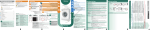
Manual de operación del EEC/c44 Hydraulic engine. START The following picture shows the way to programme the different amounts of TAA and TDR. In order to do so, you must START SLOW-DOWN STOP START SLOW-DOWN STOP operate the two keys on the controller board. The first two are used to programme the TAA time, and the following two keys are used to set TDR time. The keys painted in yellow are not used to programme TAA and TDR times. Engine controlled by a VVVF. The following picture shows the way to programme the different amounts of TAA and TDR. In order to do so, you must operate the two keys on the controller board. The first two are used to programme the TAA time, and the following two keys are used to set TDR time. The keys painted in yellow are not used to programme TAA and TDR times. JYE SRL 17 SLOW-DOWN STOP START SLOW-DOWN STOP Manual de operación del EEC/c44 Pre-opening of automatic doors. This function permits to start the opening of automatic doors before the lift gets to the selected floor. This time is programmable and it starts to run from the moment in which the levelling flag from the line opposite the one that controles the movement in the direction in which the lift is ON Stop Activates RAP ActivatesRPAP TDP 1 ON 2 3 4 5 6 7 8 1 2 3 4 5 6 7 8 7 8 TDP = 1.0 Seg. ON Slow-Down 1 TDP = 1.5 Seg. ON 2 3 4 5 TDP = 0.5 Seg. 6 7 8 1 2 3 4 5 6 TDP = 0.0 Seg. travelling is detected. For example, if the lift is travelling upwards, the first screen to be detected is the one of slow-down beginning, from the line of PAS screens; then, the levelling screen from the line of PAD screens is detected. Immediatly afterwards, The RAP relay is activated and the programmed time starts to run. Once this time has passed, The RPAP relay is activated. If the levelling screen in the PAS line is detected before the time programmed has passed, the RPAP relay activates immediatly. The keys painted in yellow are not used to programme the TDP time. JYE SRL 18 Manual de operación del EEC/c44 direction chosen, the request to change direction is ignored. Chapter 7 Subfunction Non-stop: This subfunction permits the operator to prevent the lift from stopping at the floors that were requested by hall calls; in other words, the lift will stop at the following landing requested from inside the car. If there are no calls from inside the lift, this function does not produce any chance in the calls´ attendance order. This function will keep being active until there is a call from inside the car. If it is desired to suspend hall calls, it must be requested again before the lift has set in motion. Attendant mode of operation. Contents: In this chapter there is a description of the way in which lift´s controller system must be operated when the attendant mode is chosen. Besides, there is a detailed mention of the electric requirements of the board´s inputs that allow for the activation of these group of functions. Subfunction Start: (only available for systems with automatic doors): it is the last step in order to set the lift in motion. This button needs to be pressed until the door has closed completely and the lift has started to move. If the button is released before the door has closed completely, the system will open it and wait for the Start button to be pressed. Attendant´s mode activation/ deactivation. The attendant mode is activated applying +24 Volts to the appropriate input pin in the controller board (ASC). The system will accept this function when it´s working in the automatic mode. If it´s working in the inspection mode, the attendant function, as well as its subfunctions, are ignored by the controller. However, it is possible to shift to inspection mode when the system is working in the attendant mode; and it is also possible to change from inspection mode to automatic mode when the attendant´s mode input pin is active. Attendant´s mode subfunctions. PRS, PRD, Start, Non-stop (NoP). All these subfunctions must be activated through buttons, that are normally open, that apply +24 Volts to the appropriate input pins. If the system is not working in the attendant mode, all these subfunctions and their input pins are ignored by the controller. Besides, these subfunctions must be solicited during the lapse in which the lift is still on a certain floor with its doors open. Any attempt to activate these functions while the lift is in motion will be ignored by the system. Subfunctions PRS, PRD: When calls are made in both directions, the operator can choose, with the aid of these input pins, which is the direction the lift has to move in. If there are no calls to respond to in the JYE SRL 19 Manual de operación del EEC/c44 Basic connections. Chapter 8 The picture shows the way in which the system must be interconnected, in order for it to operate in the Duplex mode Duplex mode (Descent Collective). The basic Duplex system is composed by: Contents: in this chapter there is a description of the system´s basic connections for it to operate in this mode; and there is also an explanation of the lift´s functioning under the different conditions of operation. Two controllers EEC/c44, f40 or c/22. Two DS-63 position indicators placed in the cabin. (Optional). Two or more exterior position indicators. (Optinal). Main characteristics. Duplex functioning / isolated. If one of the controllers happens to be out of order, the rest of them will work automaticaly, by itself, being able to accept and respond to the calls already asignated to the controller that has gone out of order. Rest station function: The system tries to keep, at least one of the two cabins, on the floor called Station (eventually ground DS-63 M/C Hall Calls DS-63 M/C EEC/c44, f40 or c/22 (A) LD1 LD1 LD2 DS -63 EE C/x xx LD2 LC1 LC2 LC2 LDn LDn LCn DS-63 M/C EEC/c44, f40 or c/22 (B) DS-63 LD1 M/C DS -63 EE C/x xx LC1 LD2 LC2 LDn LCn floor). Functioning with automatic/ manual doors. Functioning in the Emergency Station or in the Independent modes (Aisolated). JYE SRL The two controllers are interconnected through only one wire. (We suggest you use an electrostatic shielded cable protected by a conduit wire used exclusively for this application.) As the pictures shows, the EEC-c44 controllers, named A and B, communicate with each other through a wire that is connected to a conector placed on the right top of the controller´s board. This connector is named EEC-c44 (Tx from board A is connected to Rx from board B and vice versa). and at its right A Cabin there is a second connector of simmilar Calls appearence to which the floor and cabin indicators DS-63 are LC1 connected. 20 Each controller´s calls mede from inside the cabin keep their LCn independence, so each button is wired to its corresponding B Cabin terminal, as it is done in the case of an Calls isolated configuration. The main change is LC1 brought about in the way in which the hall LC2 calls buttons are wired. There will be one of LCn these buttons on each floor. This buttons will be wired to both controllers, connecting the terminals of the same designation. For example, in the case of a four-landings scheme the button on floor “0” will have to be wired to the “LD1” terminals of each controller; the button on floor “1” will be wire to the “LD2” terminals of each board; etc. There may be special cases in which the Manual de operación del EEC/c44 controlles have to operate cabins that differ from each other in the number of landings; and, in this situations, the hall calls, as well as the inner cabin calls, will have to be wired, so that the designations indicated on the controllers´ board labels are “one to one”. In order to clarify this, let´s consider an example: a Duplex scheme in which an “A” cabin presents seven (7) landings, indicating on each floor “-1,0,1,2,3,4,5”; and the other cabin “B” presents five (5) landings indicating at each one “0,1,2,3,4”. In this case, the calls from cabin “A” will be connected to the terminals LC1 to LC7 in board “A”, starting from button “-1” to button “5”; the calls from cabin “B” will be connected to terminals LC2 to LC6 in board “B”, starting from button “0” to button “4”; and hall calls, in the case of controller board “A”, will be connected to the terminals LD1 to LD7, starting from button “-1” to button “5”; In this way, terminals LC1, LC7, LD1 and LD7 in the “B” board will remain without connection, and both boards will have terminals LD2, LD3, LD4, LD5 and LD6 interconnected. Basic principles for functioning. The Duplex configuration seeks that, through the interconnection of two intelligent controllers, the response to calls can be optimized, in order that wait time, as well as energy consumption can be reduced. To achieve this aim, the system analyses permanentely the state of the calls taking place and, making a statistical calculation of the time that it takes to each cabin to respond to a call, it asignates it to the one that is in better conditions according to the situation. In this connection scheme there is no hierarchical structure of the kind of master-slave, but each controller is autonomous, so it does not need the others to function. It is appropriate to mention that although each board works independently in the Duplex mode, it consults the other before responding to a call to know about the other board´s situation with respect to the call. It can be said that none of the controllers tells the other which call it should respond to, but they work out together which of them is able to respond to the call in the shortest time. JYE SRL 21 Manual de operación del EEC/c44 the system to respond to calls made from inside the cabin. When the system works in the Emergency Station mode, it stops operating in the Duplex mode. Chapter 9 Duplex mode (up/down collective). Attendant mode. It allows for an operator to take control of the lift and to decide in which direction and at which moment the lift can travel. This function operates alltogether with the following functions: start (setting in motion), programme to descend (PRD) and programme to ascend (PRS). It is appropriate to mention that this function does not cancel the Duplex mode of operation, so it is possible for both boards to operate in the attendant mode or for only one of them to do so, as the other one operates in the automatic mode. Content: in this chapter there is a description of the subjects related to the interconnection and functioning of the system in the up/down Duplex mode. Principal characteristics. Duplex/ Isolated functioning. The controllers were designed to work autonomously and independently if one of them happens to be out of order or if the Duplex connection happens to be interrupted. Rest station function. When the system works in the Duplex mode it tries that there is always one cabin at the Rest Station, which is generally the ground floor. This function is not aveilable when the Duplex connection is interrupted, when one of the controllers breaks down or is out of service and when the Emergency Station or the Independent functions are activated. Basic connections. Functioning with Automatic / manual doors. They are operated from relays that permit to close and open the automatic doors using the signals end of door open (FPA) and Manual Safety (SA) to control these manouvres. In the case of having manual doors, there is a relay that commands the door switch. The controller can work with a system that combines automatic and manual doors. Two DS-63 position indicators placed in the cabin. (Optional). In the picture it is shown the way in which the controller boards must be interconnected in order to operate in the Duplex mode. The basic Duplex system is composed by: Two controllers EEC/c44, f40 or c/22. Two or more exterior position indicators. (Optinal). The two controllers are interconnected through only one wire. (We suggest you use an electrostatic shielded cable protected by a conduit wire used exclusively for this application.) As the pictures shows, the EEC-c44 controllers, named A and B, communicate with each other through a wire connected to a connector placed on the right top of the controller´s board. This connector is named EEC-c44 (Tx from board A is connected to Rx from board B and vice versa) and, to its right, there is a second connector of simmilar appearence to which floor and cabin indicators DS-63 are connected. Manual functioning (maintenance). It makes it possible for the maintenance staff or for the person in charge of setting the lift in motion to make the cabin work through the use of buttons. Independent mode functioning. This mode makes the system stop working in the Duplex mode, as the controller that operates in this mode does not respond to any hall call. Emergency Station mode functioning. This function has two stages: the first one, which starts when the system changes its mode of operation from automatic to Emergency Station, allows for the cabin to position at the rest station with its door open and the calls totally disabled; The second stage consists in the activation of the Independent mode of operation, making it possible for JYE SRL 22 Manual de operación del EEC/c44 hall and cabin calls have to be wired; in order that designations indicated on the controllers´ boards labels are ‘one to one’. To clarify this, we should have a look at the following example: suppose there is a Duplex system. Cabin ‘A’ has seven (7) landings, showing on each floor its corresponding number ‘ –1, 0, 1, 2, 3, 4, 5’; and cabin ‘B’ has five (5) landings showing on each floor its corresponding number '-1, 0, 1, 2, 3, 4’. In this case, calls from cabin ‘A’ will be connected to LC1 to LC7 terminals in board ‘A’, from button ‘1’ to Cabin calls remain independent, that is to say that each button is wired only to its corresponding terminal and there is an isolated configuration for each of them. The main change introduced is in the way hall call buttons (descent/ ascent) are wired. There will be two of them on each floor, except for the highest and the lowest floors, where there will be only one. This buttons will be wired to both controllers, being necessary for the terminals of the same designation to be connected. For example, in the case of a system of four landings, the S-63 M/C Ascent Hall Calls A Cabin Calls S-63 M/C LA1 LC1 LA1 LA2 DS -63 EEC/xxx LC1 LC2 LA2 LC2 LA(n-1) LCn LA(n-1) LCn LAn EEC/c44, F40, or C22 (A) LD1 LD2 LD2 LDn LDn S-63 Descent Hall Calls M/C S-63 LC1 LA1 M/C DS -63 EEC/XXX LC1 LC2 LA2 LC2 LA(n-1) LCn LCn LAn LD1 EEC/c44, F40, or C22 (B) LD2 LDn button ‘5’; and calls from cabin ‘B’ will be connected to LC2 to LC6 terminals in board ‘B’, from button ‘0’ to button ‘4’. As for board A, descent hall calls will be connected to LD2 to LD7 terminals (in controller board A), from button ‘-1’ to button ‘5’; and as for board b, descent calls will be connected to LD3 to LD6 terminals (in controller board B), from button ‘1’ to button ‘4’. Ascent calls will be connected in first floor button (‘1’) will be wired to the ‘LD2’ terminals of both controllers; the second floor button (‘2’) will be wired to the ‘LD3’ terminals of both controllers, etc. In the same way, ascent calls will be wired from the lowest floor to the one before the highest floor. There may be situations in which controllers have to operate cabins that differ from each other in the number of landings, under which circumstances, both JYE SRL B Cabin Calls 23 Manual de operación del EEC/c44 a similar way, wired from the highest floor to the one before the lowest one. As a result, LC1, LD1 and LA7 terminals from board ‘A’ will remain disconnected; LC1, LD1, LD2, LA1 and LA6 from board ‘B’, will also remain disconnected; and both boards will have LD3, LD4, LD5, LD6, LA2, LA3, LA4 and LA5 terminals interconnected. JYE SRL 24 Manual de operación del EEC/c44 Chapter 10 mode of operation. (Isolated). Triplex mode of peration. (Descent collective). Basic Connections. The picture shows the way in which the system has to be interconnected, in order for it to work in the Triplex mode. Contents: in this chapter there is a description of the basic connections needed for the system to operate in the triplex mode, and of the way in which this manouvre works under different situations of operation. The standadrd Triplex system is composed by: Three controllers EEC/c44, f/40 or c/22. Three position indicators DS-63 placed in the cabin. (Optional). Main characteristics. Three or more exterior position indicators. (optional). Triplex / Duplex mode of operation. If one of the controllers is out of order/ service, the other two work in the duplex mode and they are able to respond to the calls already asignated to the controller out of order. Rest station function. The system tries that there is always one cabin at the Rest Station, which is generally the ground floor. Manual and automatic doors operation. Emergency Station mode and Independent DS-63 M/C A Cabin Calls Hall Calls DS-63 M/C EEC/cXX (A) LD1 LC1 LD1 LD2 DS -63 EEC/cXX LC1 LC2 LD2 LC2 LDn LCn LDn LCn B Cabin Calls DS-63 M/C EEC/cXX (B) DS-63 LC1 LD1 M/C DS -63 EEC/cXX LC1 LC2 LD2 LC2 LDn LCn LCn C Cabin Calls DS-63 M/C EEC/cXX (C) DS-63 LC1 LD1 M/C DS -63 EEC/cXX LC1 LC2 LD2 LC2 LDn LCn LCn JYE SRL 25 The three controllers are interconnected through only one wire. (We suggest you use an electrostatic shielded cable protected by a conduit wire used exclusively for this application.) As it can be seen in the picture, EEC-cXX controllers, named A, B and C, communicate with each other through a wire that is connected to a connector placed on the right top of controller´s board. This connector is named ‘EEC-cXX’ (Tx from board A is connected to Rx from board B, Tx from board B is connected to Rx from board C and Tx from board C is connected to Rx from board A), and to its right, there is the second connector, which is very similar to the previous one, to which the floor and cabin indicators Ds-63 have to be connected. Cabin calls remain independent, that is to say that each button is wired only to its corresponding terminal and there is an isolated configuration for each of them. The main change introduced is in the way hall call buttons are wired. There will be one on each floor, except for the highest and the lowest floors, where there will be only one. This buttons will be wired to both controllers, being necessary for the terminals of the same designation to be connected. For example, in the case of a four landing system, the ‘0’ floor button has to be wired to ‘LD1’ terminals of both controllers; the the 1st floor button (‘1’) has to be wired to ‘LD2’ terminals of the two boards; etc. There may be special cases in which controllers have to operate cabins that differ in their number of Manual de operación del EEC/c44 landings. If that is the case, cabin calls, as well as hall calls, will have to be wired, in order that designations indicated on the controllers´ boards labels are ‘one to one’. To clarify this, we should have a look at the following example: suppose there is a Triplex system. Cabin ‘A’ has seven (7) landings, showing on each floor its corresponding number ‘ –1, 0, 1, 2, 3, 4, 5’; and the other two cabins, ‘B’ and ‘C’, have five (5) landings showing on each floor its corresponding number '-1, 0, 1, 2, 3, 4’. In this case, calls from cabin ‘A’ will be connected to LC1 to LC7 terminals in board ‘A’, from button ‘1’ to button ‘5’; and calls from cabins ‘B’ and ‘C’ will be connected to LC2 to LC6 terminals in boards ‘B’ and ‘C’, from button ‘0’ to button ‘4’. As regards board A, descent hall calls will be connected to LD1 to LD7 terminals, from button ‘-1’ to button ‘5’; and as regards boards B and C, descent calls will be connected to LD2 to LD6 terminals, from button ‘0’ to button ‘5’. As a result, LC1, LC7, LD1 and LD7 terminals from boards ‘B’ and ‘C’ will remain disconnected; and the three boards will have LD2, LD3, LD4, LD5 and LD6 terminals interconnected. Basic principles for functioning. Triplex configuration seeks that, through the interconnection of three intelligent controllers, the response to calls can be optimized, in order that wait time, as well energy consumption can be reduced. To achieve this aim, the system analyses permanently the state of the calls taking place and making a statistical calculation of the time that it takes to each cabin to respond to a call, it asignates it to the one that is in better conditions according to the situation. In this connection scheme there is no hierarchical structure of the kind of master-slave, but each controller is autonomous, so it does not need the others to function. It is appropriate to mention that although each board works independently in the Triplex mode, it consults the others before responding to a call to know about the other boards´ situation with respect to the call. It can be said that none of the controllers tells the other which call it should respond to, but they work out together which of them is able to respond to the call in the shortest time. JYE SRL 26 Manual de operación del EEC/c44 inside the cabin. When the system works in the Emergency Station mode it stops operating in the Triplex mode and, as long as the other two cars remain in the automatic mode, it shifts to Duplex. Chapter 11 Triplex mode of operation (updown collective). Content: in this chapter there is a description of the subjects related to the interconnection and functioning of the system in the up/down Triplex mode. Attendant mode. It allows for an operator to take control of the lift and to decide in which direction and at which moment the lift can travel. This function operates alltogether with the following functions: start (setting in motion), programme to descend (PRD) and preogramme to ascend (PRS). It is appropriate to mention that this function does not cancel the Triplex mode of operation, so it is possible for the three boards to operate in the attendant mode or for only one or two of them to do so as the other one/s operate/s in the automatic mode. Principal characteristics. Triplex/ Duplex functioning. The controllers were designed to work autonomously and independently if one of them happens to be out of order or if the Triplex connection happens to be interrupted. Rest station function. When the system works in the Duplex mode it tries that there is always one cabin at the Rest Station, which is generally the ground floor. This function is not aveilable when the Triplex connection is interrupted, when two of the controllers breaks down or is out of service and when the Emergency Station or the Independent functions are activated. Basic connections. In the picture it is shown the way in which the controller boards must be interconnected in order to operate in the Triplex mode. Functioning with Automatic / manual doors. They are operated from relays that permit to close and open the automatic doors using the signals ‘end of door open’ (FPA) and Manual Safety (SA) to control these manouvres. In the case of having manual doors, there is a relay that commands the door switch. The controller can work with a system that combines automatic and manual doors. The basic Triplex system is composed by: Three controllers EEC/cXX. Three DS-63 position indicators placed in the cabin. (Optional). Three or more exterior position indicators. (Optinal). The three controllers are interconnected through only one wire. (We suggest you use an electrostatic shielded cable protected by a conduit wire used exclusively for this application.) As the pictures shows, the EEC-cXX controllers, named A, B and C communicate with each other through a wire connected to a terminal placed on the right top of the controller´s board. This connector is named EEC-cXX (Tx from board A is connected to Rx from board B and vice versa), and to its right there is a second connector of simmilar appearence to which floor and cabin indicators DS-63 are connected. Manual functioning (maintenance). It makes it possible for the maintenance staff or for the person in charge of setting the lift in motion to make the cabin work through the use of buttons. Independent mode functioning. This mode makes the system stop working in the Triplex mode, as the controller´s that operates in this mode does not respond to any hall call. Emergency Station mode functioning. This function has two stages: the first one, which starts when the system changes its mode of operation from automatic to Emergency Station, allows for the cabin to position at the rest station with its door open and the calls totally disabled; The second stage consists in the activation of the Independent mode of operation, making it possible for the system to respond to calls made from JYE SRL 27 Manual de operación del EEC/c44 DS-63 M/C Ascent Hall Calls DS-63 M/C LA1 button (‘2’) will be wired to the ‘LD3’ terminals of the three controllers, etc. In the same way, ascent calls will A Cabin be wired from the lowest Calls floor to the one before the highest floor. There may be situations in which controllers have to operate cabins that differ from each other in the number of landings, under which circumstances, both hall and cabin calls have to be wired; in order that designations indicated on the controllers´ boards labels are ‘one to one’. To Descent Hall Calls clarify this, we should have a look at the following example: suppose there is a Triplex system. Cabin ‘A’ has seven (7) landings, showing on each floor its corresponding number ‘ –1, 0, 1, 2, 3, 4, 5’; and cabins ‘B’ and ‘C’ have five (5) B Cabin Calls landings showing on each floor its corresponding C Cabin number '-1, 0, 1, 2, 3, 4’. In Calls this case, calls from cabin ‘A’ will be connected to LC1 to LC7 terminals in board ‘A’, from button ‘1’ to button ‘5’; and calls from cabins ‘B’ and ‘C’ will be connected to LC2 to LC6 terminals in boards ‘B’ and ‘C’, from button ‘0’ to button ‘4’. As for board A, descent hall calls will be connected to LD2 to LD7 terminals (in controller board A), and as regards board B, descent calls will be connected to LD3 to LD6 terminals (in controller board B), from button ‘1’ to button ‘4’ (idem board C). Ascent calls will be connected in a similar way, wired from the lowest floor to the one before the highest one. As a result, LC1, LD1 and LA7 terminals from board ‘A’ will remain disconnected; LC1, LD1, LD2, LA1 and LA6 from boards ‘B’ and ‘C’, will also remain disconnected; and the three boards will have LD3, LD4, LD5, LD6, LA2, LA3, LA4 and LA5 terminals interconnected. LC1 LA1 LA2 DS -63 EE C/c 44 LC1 LC2 LA2 LC2 LA(n-1) LCn LA(n-1) LCn LAn EEC/cXX (A) LD1 LD2 LD2 LDn LDn DS-63 M/C DS-63 LC1 LA1 M/C DS -63 EE C/c 44 LC1 LC2 LA2 LC2 LA(n-1) LCn LCn LAn EEC/cXX (B) LD1 LD2 LDn DS-63 M/C DS-63 LC1 LA1 M/C DS -63 EE C/c 44 LC1 LC2 LA2 LC2 LA(n-1) LCn LCn LAn EEC/cXX (C) LD1 LD2 LDn Each controller´s cabin calls remain independent, that is to say that each button is wired only to its corresponding terminal and there is an isolated configuration for each of them. The main change introduced is in the way hall call buttons (descent/ ascent) are wired. There will be two of them on each floor, except for the highest and the lowest floors, where there will be only one. This buttons will be wired to the three controllers, being necessary for the terminals of the same designation to be connected. For example, in the case of a system of four landings, the first floor button (‘1’) will be wired to the ‘LD2’ terminals of the three controllers; the second floor JYE SRL 28 JYE SRL 29 S6 S4 CABIN AND HALL MANUAL DOORS. (HALL DOORS HAVE DOUBLE CONTACT SWITCH) HALL DOORS' SECOND SWITCH CAR DOOR HALL DOORS SWITCHES EMERGENCY STOP S3 CABIN AND HALL AUTOMATIC DOORS S6 HALL DOORS SWITCHES CAR DOOR EMERGENCY STOP S4 S6 S5 D ate: S6 S4 SERIE DE SEGURIDADES Tue s da y , A u gu s t 3 1, 2 00 4 D oc um ent N um ber Sheet 1 of J.Y.E. ELECTRONICA 1 CABIN AND HALL MANUAL DOORS THE HALL DOORS HAVE ONE CONTACT SWITCH CAR DOOR HALL DOORS EMERGENCY STOP S3 R ev -Safeties Serie. S ize A4 T it le AUTOMATIC CABIN DOOR AND MANUAL OR SEMI-AUTOMATIC HALL DOORS HALL DOORS' SECOND SWITCH CAR DOOR S4 HALL DOORS SWITCHES EMERGENCY STOP S3 STOP STOP STOP STOP S2 PARACHUTE S2 PARACHUTE END SWITCHES S1 S2 END SWITCHES S1 2A 110 AC V PARACHUTE END SWITCHES S1 2A 110 AC V S2 S1 2A 110 AC V PARACHUTE END SWITCHES 2A 110 AC V Manual de operación del EEC/c44 Chapter 12 Electronic diagrams: Manual de operación del EEC/c44 -Electrical engines of one or two speeds: . . . 110 ACV . 110 ACV 4A 4A HIGH SPEED - - GO UP BRAKE GO UP Pot 110 ACV BRAKE + GO DOWN LOW SPEED + 110 ACV Aar VARISTOR VARISTOR GO DOWN Pat Pat DOOR SWITCH DOOR SWITCH DOOR SWITCH PAT PAT DOOR SWITCH S5 S5 GO UP HIGH SPEED ACELERATION LAS RAV AAR GO DOWN LAB POT POTENTIAL LOW SPEED RBV GO UP GO DOWN CSU LS CDE LB GO DOWN GO UP GO UP GO DOWN S6 HIGH SPEED AA AA/AB AB LOW SPEED EEC / XXX ONE SPEED GO DOWN CSU LS CDE LB GO UP S6 GO UP J.Y.E. ELECTRONICA GO DOWN Title ONE AND TWO SPEED ELECTRIC ENGINES Size A4 EEC / XXX TWO SPEED Date: JYE SRL 30 Document Number Tuesday , August 31, 2004 Rev Sheet 1 of 1 Manual de operación del EEC/c44 - 24 Volt safeties: SAFETY BOARD 'PS-44' 24 VCC SAFETY BOARD 'PS44' 24 VCC TO CONTACT 'FPA' To Contact 'FPA' AP2 AP2 FPA (110Vac) PC LPA FPA (110Vac) EEC/XXX PA RAP S1 EEC/XXX LPA PC PA LPC PA PC RAP S1 LPC PA PC RCP S4 RCP S4 24 VCC 24 VCC SAFETY BOARD 'PS44' SAFETY BOARD 'PS44' To Contact 'SM' To Contact 'SM' S3 S4 To Contact 'SA' S6 To Contact 'SA' S6 S6 S6 AUTOMATIC DOORS 24 VCC EEC/XXX SAFETY BOARD 'PS44' 110 VCA PAT DOOR SWITCH S5 To Contact 'SM' S4 DOOR SWITCH RELAY AUTOMATIC CABIN DOORS AND MANUAL HALL DOORS. HALL DOORS HAVE DOUBLE CONTACT SWITCH WITH/WITHOUT DOOR SWITCH. To Contact 'SA' S6 J.Y.E. ELECTRONICA Title 24 VOLTS SAFETY Size A4 MAUAL DOORS Date: JYE SRL 31 Document Number Tuesday , August 31, 2004 Sheet 1 of 1 Manual de operación del EEC/c44 -Calls and services basic connections: + 24 V + 24 V CABIN CALLS ASCENT HALL CALLS LA1 LC1 LA2 LC2 LA24 LC24 + 24 V INSPECTION MODE MAN DESCENT HALL CALLS EMERGENCY STATION MODE BOM INDEPENDENT MODE IND EEC/XXX CLOSE DOORS CER OPEN DOORS ABR 'PTC' ENGINE ALT LD1 ATTENDANT MODE ASC LD2 DOES'T STOP NOP START MAR LD24 PROGRAMME TO ASCEND PRS PROGRAMME TO DESCEND PRD NO MORE ROOM CMP RELOADED J.Y.E. ELECTRONICA SBR Title CALLS AND SERVICES BASIC CONNECTIONS 24 VCC Size A4 SPECIAL FUNCTIONS Date: JYE SRL 32 Document Number Tuesday , August 31, 2004 Rev Sheet 1 of 1 Manual de operación del EEC/c44 -‘PS-44’ Safeties board connection. S6 COM S4 COM AP2 COM 18 VCA SA SM FPA +24 0V Terminal’s description: 0V: OVCC output that supplies the 0V input from the “EEC-XXX” controller board. (This input is placed between the two ALIM inputs). S6: has to be connected to the ‘S6’ contact in the safeties´ line, which has to be supplied with 110 VAC. S4: has to be connected to the ‘S4’ contact in the safeties´ line, which has to be supplied with 110 VAC. IMPORTANT: If you use the “PS-44-R” board, which has a 24VCC voltage regulator, you will have to use a 20 to 22 VCA transformer, instead of using a 18 VCA one, in order to generate a good regulation of the continuous output voltage. AP2: has to be connected to the automatic doors’ operator ‘AP2’ contact, which has to be supplied with 110 VAC. COM: 110 VCA ground. 18 VCA: has to be connected to the 18 VCA output from a transformer, that must not be the main one. Important: the maximum voltage level allowed is 18 VCA, because the PS-44 board has a full wave rectifier and a 1000 uf x 50 VCC capacitor. SA, SM, y FPA: have to be connected to ‘ECC-XXX’ board´s terminals of the same name. +24: +24VCC output that supplies any ALIM input from the “EEC-XXX” controller board. JYE SRL 33 Manual de operación del EEC/c44 -Flags, safeties serie and displays: CLOSED NORMAL MECHANICAL ENDS 220 - 380 AC 0V 18 VAC + 24 V PS 44 18 V AP2 AP2 SA E XS SAFETY BOARD E XD S4 FPA S4 SM S6 0 V S6 IND-44 IND-44 INFRARED SENSOR INFRARED SENSOR P P + + - - Display 'DS-XXX' PAD PAS E XD E XS FPA SM SA Txd S +24 V 0V ALIM 220 - 380 AC CABIN DISPLAY 0V ALIM EEC/XXX DISPLAY 'DS-XXX' 18 + 18 VAC S +24 V 0V HALL DISPLAY J.Y.E. ELECTRONICA Title Flags, safeties serie and displays Size A4 Date: JYE SRL 34 Document Number Tuesday , August 31, 2004 Rev Sheet 1 of 1 Manual de operación del EEC/c44 -Simulator´s connection: JYE SRL 35 Manual de operación del EEC/c44 Chapter 13 Position detection system with a vertical line of screes. Two-speed drives: Two position sensors are mounted in a vertical line and there must be a vertical clearence between them greater than the length of the small boards mounted between each floor (usually 10 cm). The sensor that is above the other one must be connected to a PAS, and the one below it has to be connected to a PAD. The length of ‘stop’ boards at each floor must be greater than the clearence between position sensors. EXS EXD PAS 'N' Landing End of high speed while ascending End of high speed while descending 'N-1 Landing End of high speed while ascending End of high speed while descending Stop when going down 3rd Landing Stop when going up End of high speed while ascending Door zone End of high speed while descending 2nd Landing End of high speed while ascending End of high speed while descending 1st Landing JYE SRL 36 Manual de operación del EEC/c44 One-speed drives: A position sensor connected to a PAS is needed. EXD EXS PAS 'N' Landing 'N-1'Landing Stop when going down 3rd Landing Stop when going up Door zone 2nd Landing 1st Landing JYE SRL 37 Manual de operación del EEC/c44 Flags system description for high velocity operators: N+1 Floor Fin Pre-opening Timer Pre-opening Timer trigger V3 off Floor n Pre-openingTimer off Pre-opening Timer trigger and V2 off. Minimum clearence between shift floor screens. Floor n-1 EXD EXS PAD PAS JYE SRL V3 CSU V2 38 CSU RPAP