1
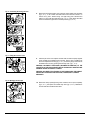
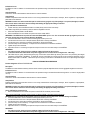
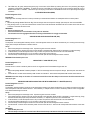
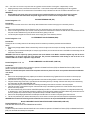
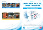
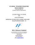
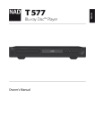
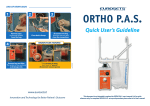
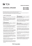
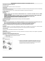
PREASSEMBLED SURGICAL WASH SET FOR DIDECO ELECTA PREASSEMBLED SURGICAL WASH SET Instructions for Use Product Designations: WS-55E, WS-125E, WS-175E, WS-225E DESCRIPTION: The Preassembled Surgical Wash Set is a device for the separation, concentration and washing of blood typically recovered from the operating field or from the extra corporeal circuit. The active component of the set is a bowl, a rotating chamber that separates components by centrifugal force. For single use only. Ethylene Oxide Sterilized. WARNINGS: - CONTENTS STERILE AND FLUID PATHS ARE NON-PYROGENIC ONLY IF PROTECTIVE PACKAGES ARE NOT OPENED, DAMAGED, OR BROKEN. - CARE MUST BE TAKEN TO MAINTAIN ITS INTERNAL STERILITY WHILE MAKING THE APPROPRIATE TUBING CONNECTIONS. - CAREFULLY READ THESE INSTRUCTIONS AND THE DIDECO ELECTA USER MANUAL PRIOR TO USE. - FOR USE ONLY WITH THE DIDECO ELECTA AUTOTRANSFUSION SYSTEM - DO NOT RESTERILIZE. CAUTION: Federal law (U.S.A.) restricts this device to sale by or on the order of a physician. Store in a cool, dry place. WARNINGS: - Do not allow halogenated liquids such as Halothane and Fluothane to come into contact with the polycarbonate parts of the device. This could cause damage which may compromise the integrity and proper functioning of the device - Do not use solvents such as alcohol, ether, acetone, etc.: as contact may cause damage to the device. CAUTION: for a detailed description of the surgical wash set please refer to Dideco Electa user manual. Intended Use The device is intended for use with specific Autotransfusion machines which are identified on the primary label. It contains the basic components necessary to process blood collected during open heart or other surgical procedures for autotransfusion. Contraindications There are no known contraindications when the device is used as intended. Complications Potential complications that have been known to occur during autotransfusion include sepsis, hemolysis, blood coagulation, coagulopathies, particulate and air embolism. PRELIMINARY OPERATIONS BEFORE INSTALLATION Before installation of the Preassembled Surgical Wash Set, complete the following: 1. Position the control panel for good vision and control 2. Lift the I.V. poles 3. Open the protective cover Set-up Fig. 1 - Mounting the kit 1. Remove the package labelled ‘’Preassembled Surgical Wash Set" from the storage carton and inspect for damage. Fit the indentation on the longest side of the container onto the handle on the right side of the unit and remove the protection sheet from the top of the container (fig. 1). 1 02348/06 – 12/2010 Fig. 2 - Mounting the reinfusion bag Fig. 3 - Positioning the bowl and the cassette onto the unit Fig. 4 - Mounting the bowl 2. Remove the reinfusion bag from the package and hang it on the higher pole (see fig. 2, no. 1). Close the flow regulator (roller clamp) on the reinfusion bag outlet (see fig. 2, no.2). Tighten the luer-lock connector between the bag and the red line connecting the bag to the bowl (see fig. 2, no.3) and check that the clamps on the same line are open. 3. Remove the protection cover from the pump segment. Take the bowl, the pump segment and the cassette from the package. Take care not to remove the protection caps from the line ends. 4. Without fastening them, fit the bowl into the centrifuge housing, the cassette and the pump segment into the corresponding housings on the panel (fig. 3) 5. Keep the three indentations (fig. 4, no.1) on the bowl base ring aligned with the corresponding metal disks on the centrifuge rotating plate and press the bowl fully downwards, ensuring that the axis is perpendicular to the rotating plate. Note: a) The wash set bowl will fit correctly only when adequate pressure is used thereby ensuring the bottom of the bowl fits ‘flush’ with the bottom of the machine centrifuge plate. b) Use two hands to press down on the body of the bowl until a ‘snap’ or ‘click’ is heard indicating that the bottom of the bowl touches the centrifuge plate evenly. c) If this sound is not obtained, remove and reattempt insertion, rotating bowl 120°. WARNING: If bowl is still not inserted correctly after several attempts, do not use it. 6. Remove the protective spacer from the upper part of the bowl (fig. 4, no.2). Fig. 5 – Inspecting the bowl for wobbling 7. Bowl Collar Look Here Do Not Look Here Bowl shoulder Manually rotate the bowl to ensure that it rotates without eccentricity, by viewing from directly above ‘shoulder’ of bowl (fig. 5). If the bowl does not rotate properly on its perpendicular axis, remove the bowl and repeat installation. WARNING: Do not attempt operation of the machine with an improperly seated wash bowl. Internal white bell 2 02348/06 – 12/2010 Fig. 6 - Connecting the bowl to the arm 8. Rotate the armlet anticlockwise, then rotate the armlet metal insert clockwise (fig. 6, no. 1), so as to fasten the metal insert around the bowl connector. In order to do so, press - without forcing - the upper rotary joint of the bowl and make it run fully inside the metal insert (fig. 6, no. 2). Then release the metal insert and check that it goes back to its initial position (fig. 6, no. 3). 9. Insert the part of the cross-shaped connector that connects the pump segment to the cassette into the bubble sensor housings. Press it down completely into the cross-shaped black housing (fig. 7, no. 1). Fit the line going to the bowl into the bubble sensor housing, pressing the tube fully down. (fig. 7, no. 2). Fig. 7 - Fitting the sensors’ cross WARNING: INCORRECT POSITIONING (INCOMPLETE INSERTION) OF THE CASSETTE ON THE CROSS-SHAPED BLACK HOUSING MAY DAMAGE PUMP SEGMENT DURING AUTOMATIC LOADING. WARNING: INCORRECT POSITIONING OF THE TUBING INSIDE THE BUBBLE SENSOR MAY CAUSE MALFUNCTIONS AND, CONSEQUENTLY, ERROR MESSAGES. Fig. 8 - Mounting the cassette 10. Rotate the clamp’s opening/closing knob clockwise until it opens completely (fig. 8, no. 1), then press the cassette fully down (fig. 8, no. 2). Release the knob to fasten the cassette and the tubes. 3 02348/06 – 12/2010 Fig. 9 - Fitting the waste fluid tube 11. Insert the waste line into the waste line holder (fig. 9, no 1). Ensure that the tube is not twisted or kinked. 12. Prior to closing centrifuge cover, ensure cassette and tubing segment going to the bowl are fully down into the cross-shaped black holder: press them down completely into their seats (fig 7, no. 1 and no. 2). 13. Close and lock the cover. Ensure that the tubings are not occluded. 14. Remove the waste bag and discard the container. Hang the bag on the handle on the right side of the unit. Check that the measuring scale is visible and the drain valve is easily accessed. Prior to using the disposable set, ensure that the drain valve is closed. 15. If you are not going to perform any preoperative sequestration procedure prior to intraoperative recovery, connect the bowl to the waste bag by means of the line previously connected to the bowl. When performing sequestration procedures, the bowl must be connected to the appropriate collection set (code 150) or Blood Component Collection Set with Direct Draw Line (code 151E). 16. Close the wash line clamp (yellow) and insert one of the spikes into the wash solution container. Then open the corresponding clamp. 17. Ensure that the unit is on. During the set-up procedure, the pump segment is automatically loaded. 18. If you are not going to perform any preoperative sequestration procedure prior to intraoperative recovery, connect the blue coded line to the corresponding port on the autotransfusion cardiotomy reservoir. When performing sequestration procedures, the bowl must be connected to the appropriate collection set (code 150) or Blood Component Collection Set with Direct Draw Line (code 151E). WARNINGS: - Do not use pressure cuff. Pressurized reinfusion is not indicated as it may cause air embolism - If during centrifugal rotation abnormal noise, vibration or wobbling is detected, do not use the bowl. - Use of 40 microns micro-aggregate filter when re-infusing collected blood is strongly recommended Note: If the wash set is to be used in conjunction with an autotransfusion cardiotomy only, complete Steps 18 and 19. 19. If using a cardiotomy reservoir requiring a 3/8" adapter, obtain a Cardiotomy "Y" Adapter Set (CYA). Connect the 3/8” connector to the cardiotomy outlet. Connect one of the two ¼’’ branch to the correspondent inlet connector on the wash set. Close the clamp on the other 1/4" connector branch. Ensure that the clamp on the branch of the CYA connected to the wash set is open. WARNINGS: - Prime the cardiotomy reservoir with anticoagulant solution prior to use - To minimize blood cells trauma Sorin Group Italia suggest the use of vacuum levels not higher than - 100 mmHg. 20. Inspect tubing to ensure there are no twists, kinks or flat spots. Note: If the wash set is to be used in conjunction with an oxygenator, read carefully the paragraph: ASPIRATION AND ANTICOAGULATION LINE WITH CARDIOTOMY “Y” ADAPTER of the section of the Instructions for use entitled ‘’AUTOTRANSFUSION RESERVOIRS AND ACCESSORIES’’ AUTOTRANSFUSION RESERVOIRS AND ACCESSORIES Instructions for Use For single use only Ethylene Oxide Sterilized. Contents sterile and fluid paths are non-pyrogenic only if protective packages are not opened, damaged, or broken. WARNINGS: - CAREFULLY READ THESE INSTRUCTIONS AND THE MANUAL FOR THE SORIN GROUP ITALIA CORRESPONDING EQUIPMENT PRIOR TO USE. - FOR USE ONLY WITH SORIN GROUP ITALIA ELECTA, AND COMPACT ADVANCED AUTOTRANSFUSION SYSTEM - DO NOT RESTERILIZE. Caution: Federal law (U.S.A.) restricts this device to sale by or on the order of a physician. Store in a cool, dry place. Product designation: BT844 ATS RESERVOIR. BT844 AUTOTRANSFUSION RESERVOIR Description The BT844 is a 3 liters filtered cardiotomy reservoir which contains a polyester depth filter which removes aggregates larger than 40 microns. 4 02348/06 – 12/2010 Indications for use The BT844 is used for collection of recovered blood to be processed using an autotransfusion/cell washing device. It is used for single patient use only. Contraindications There are no known contraindications when the device is used as intended. Complications Potential complications that have been known to occur during autotransfusion include sepsis, hemolysis, blood coagulation, coagulopathies, particulate and air embolism. WARNING: Contents are sterile and the fluid path is sterile and non-pyrogenic only if the package is not opened, damaged, or broken. Care must be taken to maintain its internal sterility while making the appropriate tubing connections. Set-up of BT 844 for autotransfusion 1. Position and firmly secure the BT844 Holder to a vertical pole by means of the screw clamp. Note: When using Electa, the cardiotomy reservoir holder is integrated in the unit. 2. Mount and latch the BT844 re-usable SHELL. 3. Remove the BT844 from its container and place it into the re-usable SHELL. WARNINGS: The BT844 must be positioned inside the BT844 SHELL prior to use. Do not exceed 300 mm Hg negative pressure as excessive vacuum may cause structural damage to the BT844. 4. Prime the BT844 with a minimum of 200ml of anticoagulant solution prior to use. 5. Connect the suction line to one of the ports marked "SUCTION" on the top of the BT844. 6. Connect the vacuum line to the port marked "VACUUM" on the top of the BT844. 7. Close the clamps on the Cardiotomy "Y" Adaptor lines and all other lines connected to the BT844. 8. Tighten all caps and connections. 9. Adjust the vacuum to -100 mm Hg and open the clamp to the vacuum source when ready to use the BT844. WARNINGS: - For safe processing, during use keep a minimum of 200 ml of blood into the reservoir. - To minimize blood cells trauma Sorin Group Italia suggest the use of vacuum levels not higher than - 100 mmHg. 10. The BT844 may be gravity drained through the plug on the bottom of the BT844 by relieving the vacuum and puncturing the integral membrane on the bottom of the BT844. To relieve the vacuum in the BT844, shut off the vacuum source and pull the yellow tab on top of BT844 marked "PULL TO RESET". Remove the cap from the plug on the bottom of the BT844 and insert an IV spike through the integral membrane. BT894 AUTOTRANSFUSION RESERVOIR Product designation: BT894 ATS RESERVOIR. Description The BT894 is a 4 liters filtered cardiotomy reservoir which contains a polyester depth filter which removes aggregates larger than 40 microns. Indications for use The BT894 is used for collection of recovered blood to be processed using an autotransfusion/cell washing device. It is used for single patient use only. Contraindications There are no known contraindications when the device is used as intended. Complications Potential complications that have been known to occur during autotransfusion include sepsis, hemolysis, blood coagulation, coagulopathies, particulate and air embolism. WARNING: Contents are sterile and the fluid path is sterile and non-pyrogenic only if the package is not opened, damaged, or broken. Care must be taken to maintain its internal sterility while making the appropriate tubing connections.. Set-up of BT 894 for autotransfusion 1. Remove the BT894 from its container and place it on the ELECTA cardiotomy reservoir holder. Note: a stand-alone BT894 cardiotomy reservoir holder is needed if BT894 is used with Compact Advanced WARNING: Do not exceed 300 mm Hg negative pressure as excessive vacuum may cause structural damage to the BT894. 2. Prime the BT894 with a minimum of 200ml of anticoagulant solution prior to use. 3. Connect the suction line to one of the ports marked "SUCTION" on the top of the BT894. 4. Connect the vacuum line to the port marked "VACUUM" on the top of the BT894. 5. Close the clamps on the Cardiotomy "Y" Adaptor lines and all other lines connected to the BT894. 6. Tighten all caps and connections. 7. Adjust the vacuum to -100 mm Hg and open the clamp to the vacuum source when ready to use the BT894. WARNINGS: - For safe processing, during use keep a minimum of 200 ml of blood into the reservoir. - To minimize blood cells trauma Sorin Group Italia suggest the use of vacuum levels not higher than - 100 mmHg. 5 02348/06 – 12/2010 8. The BT894 may be gravity drained through the plug on the bottom of the BT894 by relieving the vacuum and puncturing the integral membrane on the bottom of the BT894. To relieve the vacuum in the BT894, shut off the vacuum source and pull the yellow tab on top of BT894 marked "PULL TO RESET". Remove the cap from the plug on the bottom of the BT894 and insert an IV spike through the integral membrane. 1 LITER REINFUSION BAG (BRB1) Product Designation: BRB1 Intended Use These bags serve as holding reservoirs for blood processed by an autotransfusion Machine for subsequent reinfusion into the patient. Set-up 1 Remove the package labelled "Reinfusion Bag" from the storage carton and inspect for damage. Open the pouch and remove the BRB1. 2. Hang the bag on the I.V. pole of the autotransfusion machine and connect the line with the female luer-lock connector to the male luer-lock connector on the wash set reinfusion line. WARNINGS: - Do not use pressure cuff. - Pressurized reinfusion is not indicated as it may cause air embolism. - Use of 40 microns micro-aggregate filter when re-infusing collected blood is strongly recommended Product Designation: AAL ASPIRATION AND ANTICOAGULATION LINE (AAL) Intended Use The Aspiration and Anticoagulant Assembly serves to add anticoagulant solution to the blood simultaneously as it is being recovered during surgery and to transport the mixture to collection reservoir. Set up 1. Remove the package from the storage carton. Open the bag and remove the contents. 2. Using sterile technique, open the sash wrap and pass the AAL to the sterile field. (Note: the AAL is packaged in a single sash wrap). 3. In the sterile field, connect the aspirator to the 3-way connector and pass the other end of the AAL out of the sterile field. 4. Connect the capped aspiration line to a 1/4" connector on the suction source (reservoir). 5. Close the clamp on the anticoagulant solution line and insert the spike into the anticoagulant solution container. WARNING: Prime the AAL prior to use Product Designation: CYA CARDIOTOMY "Y" ADAPTER SET (CYA) Intended Use This line serves to connect a cardiotomy reservoir and/or an oxygenator to the Preassembled Surgical wash set. Set-up 1. Remove the package labelled "Cardiotomy Adapter "Y" Set" from the storage carton and inspect for damage. Open the pouch and remove the CYA. 2. Connect the 3/8” connector to the cardiotomy outlet. Connect one of the two ¼’’ branch to the correspondent inlet connector on the wash set. WARNING: Close the clamp on the other 1/4" connector branch. Ensure that the clamp on the branch of the CYA connected to the wash set is open. ASPIRATION AND ANTICOAGULATION LINE WITH CARDIOTOMY "Y" ADAPTER (AALCYA) Product Designation: AALCYA Intended Use The Aspiration and Anticoagulant Line serves to add anticoagulant solution to the blood simultaneously as it is being recovered during surgery and to transport the mixture to collection reservoir.. The Cardiotomy "Y" Adapter serves to connect a cardiotomy reservoir and/or an oxygenator to the Preassembled Surgical wash set. Set up 1. Remove the package from the storage carton. Open the bag and remove the contents. 2. Using sterile technique, open the sash wrap and pass the AAL to the sterile field. (Note: the AAL is packaged in a single sash wrap). Using the same sterile technique open the pouch labelled "Cardiotomy "Y" Adapter and pass the CYA to the sterile field. 3. In the sterile field, connect the aspirator to the 3-way connector and pass the other end of the AAL out of the sterile field. 4. Connect the capped aspiration line to a 1/4" connector on the suction source (reservoir). 5. Close the clamp on the anticoagulant solution line and insert the spike into the anticoagulant solution container. 6. Connect the 3/8” connector to the cardiotomy outlet. Connect one of the two ¼’’ branch to the correspondent inlet connector on the wash set. WARNINGS: - Prime the AAL prior to use. - Close the clamp on the other 1/4" connector branch. Ensure that the clamp on the branch of the CYA connected to the wash set is open. 6 02348/06 – 12/2010 Note: If the CYA is to be used in conjunction with an oxygenator at the termination of the bypass, complete Steps 7 and 8 7. Keeping the clamp closed, connect the second of the two ¼’’ branch to the correspondent cardioplegia port of the oxygenator. 8. Open the clamp on the 1/4" connector branch. Ensure that the clamp on the branch of the CYA connected to the wash set is open. WARNINGS: - Ensure that the roller pump of the extra corporeal circuit is switched off before to connect the CYA to the oxygenator. - To minimize blood cells trauma Sorin Group Italia suggest the use of vacuum levels not higher than - 100 mmHg. Product Designation: VEL VACUUM EXTENSION LINE (VEL) Intended Use This line serves to transfer vacuum from a Sorin Group Italia Autotransfusion machine and supply it to a cardiotomy reservoir. Set-up 1. Remove the package labelled "Vacuum Extension Line" from the storage carton. Open the pouch and remove the VEL. 2. Press in on the ring around the quick connect on the rear panel of the autotransfusion machine and seat the blue connector of the VEL into the quick connect. Release the ring and check the connection by pulling on the line. 3. Connect the yellow capped end of the VEL to the vacuum supply port on the cardiotomy reservoir. Product Designation: WCB 10 LITERS WASTE COLLECTION BAG (WCB) Intended Use This bag serves as a holding reservoir for the waste products from the blood processed by the Autotransfusion Machine. Set-up 1. Remove the package labelled "Waste Collection Bag" from the storage carton and inspect for damage. Open the pouch and remove the WCB. 2. Hang the bag on the machine handle (left for Compact; right for Electa) and connect the inlet line on the WCB to the line leading from the wash bowl on the wash set. WARNING: Fluid can be emptied by opening the drain tube at the bottom of the WCB. It should be emptied only until the level is approximately 2 cm from the upper part of the drain tube. This prevents contamination inside the bag as well as the loss of air contained within the set that is required to empty the bowl. Product Designation: COD. 150 BLOOD COMPONENT COLLECTION SET (CODE 150) Intended Use The Blood Component Collection Set is intended for separation of Platelet-Poor Plasma (PPP) and Platelet-Rich Plasma (PRP) from the patient’s whole blood collected into transfer bags. Caution: for a detailed description of the blood component collection set please refer to the correspondent Autotransfusion Machine user manual. Set-up 1. Remove from the packaging the 4-way adapter pre-connected to the collection bag. Tighten the luer-lock connector to ensure proper connection to the collection bag. 2. Attach the line of the 4-way adapter with largest diameter to the male luer fitting located on the bowl connection line of the wash set. 3. Hang the collection bag on the unit’s IV pole with the inlet line entering at the top of the bag. Close the roller clamp on the collection bag line marked with "CLOSE CLAMP BEFORE USE". 4. Set up the waste bag on the unit and attach the waste bag inlet tubing to the male luer connector of the 4-way adapter. 5. Open the red clamp on the collection bag line. Close the white clamp on the waste bag collection line. Close the blue clamp on the free branch of the 4-way adapter. 6. The second collection bag can be used to collect PRP separately from PPP or, at the end of the procedure, to change the reinfusion bag on the wash set. In case a double bag procedure is preferred, connect the second collection bag (PRP collection bag) to the free branch of the 4-way adapter and proceed as in step 3. Keep the blue clamp on the PRP collection bag closed. 7. Remove from the packaging the extension line with spike and attach the 1/4" connector to the priming line of the wash set. 8. The luer-lock protective caps, sealed in the small pouch, can be used to cover the open lines at the end of the sequestration procedure. WARNING: Do not attach the waste bag and the autotransfusion reservoir to the respective WASH SET connection lines BLOOD COMPONENT COLLECTION SET WITH DIRECT DRAW LINE (CODE 151E) Product Designation: COD. 151E FOR USE ONLY WITH ELECTA AUTOTRANSFUSION SYSTEM Intended Use The Blood Component Collection Set with Direct Draw Line is intended for separation of Platelet-Poor Plasma (PPP) and Platelet-Rich Plasma (PRP) from the whole blood directly from the patient. 7 02348/06 – 12/2010 Caution: For a detailed description of the Blood Component Collection Set with Direct Draw Line please refer to ELECTA user manual. Set-up 1. Remove the tubing assembly from the packaging and close roller clamps. 2. Attach the extension line with 1/4’’ connector to the priming line of the wash set. 3. Keep the clamp closed until the procedure starts. 4. Hang the CPD anticoagulant solution container on an I.V. pole and push vented spike into the container. Open the vented port only if container requires venting. 5. Open roller clamp and allow fluid to fill the line with at least 100 ml of solution. Close clamp. 6. Open the roller clamp. Remove the protective cap from the luer-lock connector to be attached to the patient’s drawing needle, and prime the line with anticoagulant solution until fluid drips out from the luer-lock connector. 7. Close roller clamp after ensuring that all air in the line is eliminated. Recap the connector until the needle is attached. 8. Open roller clamp and refill drip chamber to the previous level. Close clamp. 9. Attach the needle at patient draw site to the luer-lock connector. The luer-lock protective caps, sealed in the small pouch, can be used to cover the open lines at the end of the procedure WARNING: Prior to start the procedure read carefully the ELECTA user manual LIMITED WARRANTY This Limited Warranty is in addition to any statutory rights of the Purchaser pursuant to applicable law. SORIN GROUP ITALIA warrants that all reasonable care has been taken in the manufacture of this medical device, as required by the nature of the device and the use for which the device is intended. SORIN GROUP ITALIA warrants that the medical device is capable of functioning as indicated in the current instructions for use when used in accordance with them by a qualified user and before any expiry date indicated on the packaging. However, SORIN GROUP ITALIA cannot guarantee that the user will use the device correctly, nor that the incorrect diagnosis or therapy and/or that the particular physical and biological characteristics of an individual patient, do not affect the performance and effectiveness of the device with damaging consequences for the patient, even though the specified instructions for use have been respected. SORIN GROUP ITALIA, whilst emphasizing the need to adhere strictly to the instructions for use and to adopt all the precautions necessary for the correct use of the device, cannot assume any responsibility for any loss, damage, expense, incidents or consequences arising directly or indirectly from the improper use of this device. SORIN GROUP ITALIA undertakes to replace the medical device in the event that it is defective at the time of placing on the market or whilst being shipped by SORIN GROUP ITALIA up to the time of delivery to the final user unless such defect has been caused by mishandling by the purchaser. The above replaces all other warranties explicit or implicit, written or verbal, including warranties of merchantability and fitness for purpose. No person, including any representative, agent, dealer, distributor or intermediary of SORIN GROUP ITALIA or any other industrial or commercial organization is authorized to make any representation or warranty concerning this medical device except as expressedly stated herein. SORIN GROUP ITALIA disclaims any warranty of merchantability and any warranty of fitness for purpose with regard to this product other than what is expressedly stated herein. The purchaser undertakes to comply with the terms of this Limited Warranty and in particular agrees, in the event of a dispute or litigation with SORIN GROUP ITALIA, not to make claims based on alleged or proven changes or alterations made to this Limited Warranty by any representative, agent, dealer, distributor or other intermediary. Distributed in U.S. by: SORIN GROUP ITALIA 41037 MIRANDOLA (MO) - Italy Via Statale 12 Nord, 86 Tel.: Tel. 39/535/29811 Fax: Fax 39-0535-25229 Sorin Group USA, Inc. 14401 W. 65th Way Arvada, CO 80004-3599 Tel. (800) 221-7943 · (303) 425-5508 Fax: (303) 467-6584 8 02348/06 – 12/2010