1
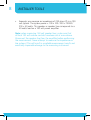
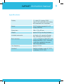
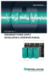
Installed Sound Solutions
IMPMET
Instruction manual
IMPMET Instruction manual
Safety instructions
• Read this manual before using this measuring instrument.
• Only use this instrument as specified in this manual.
• Do not use the instrument on live systems.
• Always
disconnect the speaker lines from the power amplifiers
before attempting to perform a measurement.
• A
lways connect the test leads before activating the
measurement cycle.
• D
o not connect or disconnect the test leads while the
measurement is active.
• To avoid electrical shock, do not touch any live parts.
• Make sure the object to be measured has no electrical charge.
• Do not use this instrument near explosive gas, vapor or dust.
3
4
INSTALLER TOOLS
Product overview
• T rue impedance measurement of loudspeakers and speaker
lines up to 2000 ohms at 330 Hz. Measuring frequency
optimized for real life impedance measurements on Lo-Z and
100 volt speaker lines.
• Three test ranges: 0-20, 200 and 2000 ohms.
• Battery powered, uses 6 x AA batteries, long battery life.
• “Low battery” indication.
• “Data hold” function.
• Timer-operated measurement cycle, approx 30 seconds.
• LOCK-function for continuous measurement.
• Auto power off, after approx 15 minutes of inactivity.
• 2
000 count LCD display with switchable backlight and 10
seconds backlight timer.
IMPMET Instruction manual
1
4
5
6
7
2
8
3
1. COM connector: 4 mm black insulated banana jack for black
test lead (common).
2. Ω connector: 4 mm red insulated banana jack for red test
lead (+).
3. Testing LED: this red LED lights up when the unit is performing
a measurement cycle.
4. TEST button: Push the button to start the measurement. The
“testing” LED will light up. After approximately 30 seconds, the
5
6
INSTALLER TOOLS
measurement will stop automatically. If you want to stop the
measurement manually, push the button once again.
5. LOCK key: for continuous measurement. Press this key while
the test is running. “LOCK” appears in the display, indicating
that test mode is continuous. Pressing the test button disables
continuous measurement.
6. HOLD key: press this key to freeze the present display reading.
To exit hold mode, press the key once again.
7. BACKLIGHT key: enable or disable the display backlight.
8. FUNCTION switch: turn the function switch from the OFF
position to the desired measuring range: 20, 200 or 2000
ohms. When the measurement is out of range, the symbol “I”
will appear in the display. The highest measurable impedance is
1999 ohms. This equals about 5 watts in 100 volt.
IMPMET Instruction manual
Using the IMPMET
Getting started: Turn the function switch to the OFF position.
Remove the test leads if present and unscrew the bottom battery
cover by removing the four screws. Insert 6 fresh AA alkaline
batteries. Mind the polarity! Put the cover back in place and
tighten the four screws using a light touch. Remove the batteries
and store them in a safe place when the unit is not used for more
than 30 days, or when the batteries are exhausted. When the low
battery symbol appears in the display, the batteries need to be
replaced. Discard exhausted batteries according to your local waste
management regulations.
Performing a measurement and calculating system power in 100
volt speaker lines:
• M
ake sure the system under test is disconnected from the
power amplifier.
• C
onnect the test leads to the speaker/speaker line. Set the
function switch to the expected range. Press the test button.
The display will show the measured impedance. When the
symbol “I” appears in the display, the value is out of range.
Switch to a higher range and perform a new measurement.
• T he unit can measure impedance up to 2000 ohms. This is
equivalent to 5 watts in 100 volt. The formula for determining
the power in 100 volt systems: P = Z.I² = V²/Z where Z is the
impedance value measured. For 100 volt systems, the power =
(100 x 100) / Z = 10000 / Z
7
8
INSTALLER TOOLS
• E xample: you measure an impedance of 250 ohms (Z) in a 100
volt system. The system power = 100 x 100 / 250 = 10000 /
250 = 40 watts. This speaker or speaker line corresponds to a
40 watts load on a 100 volt power amplifier.
Note: when measuring 100 volt speaker lines, make sure that
all local 100 volt volume controls have been set at max volume.
Disconnect the speaker line from the amplifier before performing
the measurement. Never attempt to measure the impedance on
live systems! This will result in unreliable measurement results and
eventually irreparable damage to the measuring instrument.
IMPMET Instruction manual
Specifications
Display
3 ½ digit LCD display (2000
counts) with data hold, low battery
and measured units indication.
Power
9 VDC battery powered: 6 x AA
battery (alkaline)
Dimensions
168 x 110 x 62 mm
Weight
approx. 500 g including batteries
Included accessories
test leads with separate alligator
clips, soft bag and user manual
Basic accuracy
+- 2% + 2 digits at 18 to 28°C and
relative humidity <75%. Accuracy
is valid for a period of one year
after initial calibration
Test frequency
approx. 330 Hz
Standard
Double insulation, meets IC-1010.
Installation CAT III 100V
9
10
INSTALLER TOOLS
Notes
developed
by
Audioprof nv
Industriepark Brechtsebaan 8 bus 1
2900 Schoten - Belgium
Company names, product names and trademarks are property of their
respective owners.
Apart-Audio specifications are subject to change without notice.