1
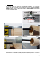
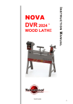
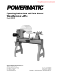
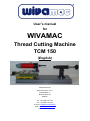
User’s manual for WIVAMAC Thread Cutting Machine TCM 150 (English) Manufactured by Willy Vanhoutte b.v.b.a. Industriepark 11 B-8730 Beernem Belgium Tel: + 32-(0)50 78 17 94 Fax: +32-(0)50 78 19 64 E-mail : [email protected] Web : www.willyvanhoutte.be www.wivamac.com Content: 1. INTRODUCTION 1.0. Safe Operation 1.1. Safe Working Practices 3 3 2. COMPONENTS 2.1. The thread cutter 2.2. The thread pitch feeding system 5 5 5 3. ADJUSTMENTS 3.1 Compound table 3.1.1. Alignment 3.2. Feeding system 3.2.1. Height positioning 3.3. Cutter positioning 6 6 5 6 6 7 4.PREPARING THE CORRECT DIAMETERS 8 5. CUTTING THE THREAD 8 6. CHANGING TO ANOTHER PITCH 9 7. VERTICAL MILLING POWER TOOL 9 8. DISCLAIMER 9 2 Thread Cutting Machine TCM 150 1. INTRODUCTION 1.1. Safe Operation Your personal safety is your own responsibility. You are also responsible for the safety of others who may be within the area around the machinery. Do not operate this Tread cutting machine if you are under the influence of alcohol or drugs (including prescription drugs), or if you are tired. Beware of jewellery, neck-ties and scarves, long hair, frayed and torn clothing or other items of clothing or personal equipment which may become tangled in rotating parts. Before commencing to operate this machine, ensure that you are aware of all relevant operational and safety procedures and the position and functioning of all controls. The machinery must be operated only in accordance with both the instructions provided and with best practice within industry. It is the operator’s responsibility to ensure that the techniques and methods of operation used comply with all relevant Health and Safety Regulations which may be applicable at the place of operation or in the industry in which the Tread cutting machine is used. If in doubt STOP. Be aware that although the Tread cutting machine is not rotating, the power supply may be connected and the Tread cutting machine ready to operate. It is possible that the Tread cutting machine spindle is about to commence accelerating to operational speed, albeit this may not be immediately visible when approaching the Tread cutting machine. The Tread cutting machine must be installed in accordance with good practice and with reference to the instructions and specifications provided. All power supplies and cabling should be installed in compliance with the appropriate regulations ruling in your area. All exposed cabling should be regularly inspected, with the power supply disconnected, to ensure that the cable is not damaged and that the insulation is sound. Damaged or worn cables should be replaced before the Tread cutting machine is operated again. Do not work on electrical equipment with wet hands, or if the machinery is itself wet due to the effects of condensation, rain or other sources of free water. Observe all safety and warning notices on the machine. Do not deface, obliterate, cover or remove any such warnings. 1.2. Safe Working Practices Woodworking can be dangerous. You are strongly advised to take a course of instruction in the craft from a competent teacher, before you use this Tread cutting machine, unless you have significant prior experience of woodworking. Do not operate this Tread cutting machine if you are under the influence of alcohol or drugs (including prescription drugs), or if you are tired. Beware of jewellery, neck-ties and scarves, long hair, frayed and torn clothing or other items of clothing or personal equipment which may become tangled in rotating parts. Close-fitting clothing with cuffs closed by cinching is recommended. Children should not be permitted to operate the Tread cutting machine. Young people should be properly supervised by a competent adult when using the Tread cutting machine. Do not talk or allow yourself to become otherwise distracted whilst operating the Tread cutting machine. Ensure that work pieces are mounted on the Tread cutting machine securely. Before starting the Tread cutting machine under power, rotate the workpiece through at least one full revolution to ensure that no part of it can contact any part of the Tread cutting machine or associated equipment. 3 Always start the Tread cutting machine at slow speed and check that the mounting of the workpiece is secure before commencing work on it. Work with due care and be especially aware of the risks to eyes, fingers and hands. If in doubt, STOP the machinery. If the Tread cutting machine vibrates significantly in operation, it is an indication that the work is being turned at too high a speed. If this happens, STOP the Tread cutting machine immediately. Do not re-start until a lower speed has been selected. If no lower speed is available, then some of the out-of-balance load will need to be balanced, before re-starting. For most types of cutters timber a turning speed of 8.000rpm is recommended. When leaving the work area switch the Tread cutting machine off and withdraw the power supply plug from the socket. Do not attempt to slow or stop the Tread cutting machine’s rotation by applying a hand to the spindle. This Tread cutting machine is designed for the turning of wood only. Most woodturning operations give rise to dust. Dust is potentially very injurious to health and is a cause of cancer and other serious illnesses. Operators (and those working in the same environment) should wear personal protective equipment (such as a respirator) and environmental dust should be minimised by the use of an effective dust extraction system placed close to the source of the dust hazard. Don’t be fooled by what you can’t see! The most injurious dust is that which is too small to be easily seen. Always assume that dust is present and protect yourself against it. Wear eye protection with an industrial impact rating at all times when working on the Tread cutting machine. Ear protection is also recommended as it will help reduce aural degeneration, which is a cumulative effect. The use of accessories and replacement parts supplied by third parties may expose the user to hazards. The use of approved accessories and the fitting of spare parts ® supplied by the original equipment manufacturer (WivaMac ) is strongly ® recommended. WivaMac will not be responsible under product liability regulations for any damage resulting from the use of parts and accessories from other sources. The operational instructions (this manual) should be made available to all operators of this machinery and operators should be advised of the potential hazards of Tread cutting machine operation, including environmental risks, before they are allowed to use the Tread cutting machine. Do not operate the Tread cutting machine with covers removed or other safety equipment broken, disabled, missing or otherwise inoperative. Repairs to the Tread cutting machine and its installation should be undertaken only by qualified personnel. Always disconnect the power supply before opening or working on associated electrical equipment. Be aware that potentially lethal residual voltages may be present for some minutes even after the power source has been removed. Always wait several minutes after removing power from the Tread cutting machine before accessing the electrical equipment. Do not rely on simply switching off power when working on the electrical system: ALWAYS disconnect the power supply physically from the equipment before commencing to work on it. 4 2. COMPONENTS The thread cutting machine consists of following components: see picture 1. Picture 1 Photo 11 2.1. The thread cutter (A), which is fitted in high speed milling power tool (B) that has been mounted on a compound table (C). This compound table is fixed on a base plate (D). The cutter can be positioned by means of the compound table at the outside for making external screw thread or the inside for making internal screw thread on the already on the lathe prepared lids and containers. 2.2. The thread pitch feeding system (E), is also fixed on the same base plate. The pitch feeding system and compound table can be fixed at different locations see pictures 3 and 2, in order to adjust the system to the height of the products to be threaded. Picture 2 Picture 3 It has standard been installed with a thread feeding system with a pitch of 2mm. Other feeding systems with a pitch of 1.5mm, 1.75mm, 2mm and 2.5mm are also available as an option, see also 6. Cutting the thread. 5 3. ADJUSTMENTS Following adjustments should be done before making external and internal screw threads. 3.1 Compound table 3.1.1. Alignment The compound table (C) needs to be correctly aligned parallel with the centre line and edges of the base plate (D) as shown in picture 4. This alignment has already been done at the factory, but in case one has dismounted the compound table (C) for any or another reason a realignment needs to be done. Picture 4 3.2. Feeding system 3.2.1. Height positioning (pictures 5,6 & 7) Picture 5 Picture 6 The centre line of the pitch feeding system needs to be at the same height as the cutter (power tool) centre line. This is a onetime adjustment. First unlock all screws (L & K). Adjust the centreline of the pitch feeding system (E) at the same height as the centreline of the thread cutter (A). Once the height adjustment has been done, one should position the adjustment securing ring down against the base and lock screw (L). Picture 7 6 3.3. Cutter positioning By turning the specific hand wheels of the compound table, see picture 8, one can move the position of the cutter to the outside of the pre-turned product for making male thread, see pictures 9 & 10 or inside the product for making female thread, see pictures 11 & 12. The cutter should touch the perimeter of the wood. Picture 8 Male thread Picture 9 Picture 11 Female thread Picture 10 Picture 12 Before starting to cut the thread one should verify whether the product is positioned centric around the centre line and does not wobble by rotating the pitch feeding screw (F), 7 If not centric, reposition the product in the chuck until it is rotating perfectly centric. If not the screw thread will not be evenly deep over the circumference. In order to avoid this adjustment process, we recommend to leave the product, that have been preturned on the late, in the chuck and mount the chuck with the product directly on the thread pitch screw (E), without repositioning it. The standard screw thread to mount the chuck on the pitch feeding system is M33 x 3.5mm. Eventually an adapter can be used. 4. PREPARING THE CORRECT DIAMETERS When preparing the work pieces, care must be taken that the diameter of the section where external threads are going to be cut “D” in picture 13 is greater than the diameter of the mating section where internal threads are being cut “d” in picture 13. d = D – 1 x pitch The difference between these two diameters may not be greater than once the pitch of the thread. If, for example you want to cut a thread with a 2mm pitch on a 40mm piece of wood, then the hole for the internal thread should not be smaller than 40mm – 2mm = 38mm. If the wood is not completely dry, which is often the case, it is advisable to make the difference between the two diameters just a little less. Picture 13 5. CUTTING THE THREAD Mount your prepared work piece, secured in the chuck, onto the threading jig spindle. Make sure that the chuck is securely in place so that it cannot come loose when turning to the left. Now bring the work piece up to the cutter by using the hand wheels as shown in 3.3 Cutter positioning, pictures 9 & 10. The depth of cut is adjusted by using the hand wheel in the back. It is recommended not to cut the complete depth at once. One will get a cleaner cut if this is done in several steps. In order to know the exact depth, one can put the index ring of the hand wheel at zero. Make sure you turn the handle enough backwards before advancing the table deeper into the thread in order to eliminate the clearance of the system. Now carefully turn the workpiece slowly against the cutter by using the knob fixed at the end of the pitch feeding screw (F). After attaining the desired thread length, simply rotate the work piece back in the opposite direction. While cutting the thread the work piece has shifted in relation to the cutter. The speed and the evenness with which the work piece is turned against the cutter has no influence on the evenness of the pitch. The depth or height of the thread is in general equal to, or better inferior than the pitch (the cutter, and hence the thread form, have a 60 degree included angle), meaning you one should leave a little flat on the top of the screw thread. Completing the thread to full depth normally requires 2 to 4 passes with the cutter, each pass being set to give a greater depth of cut. 8 6. CHANGING TO ANOTHER PITCH The threading jig is standard fitted with an interchangeable thread pitch feeding system (E) – a threaded rod (F) with a 2mm pitch; the thread that you are going to cut into the wood will therefore have a pitch of 2mm. This type of thread is particularly suitable for making boxes with screw lids. The thread pitch screw/nut (F & J) combination can easily be changed to give another pitch if so desired. Picture 14 The thread pitches available are: 1.5mm, 1.75mm. 2.0mm. and 3 m. To change the combination you should fully unscrew the thread pitch screw, see (F) until you see a socket screw in the hole (G) in picture 14 of the horizontal bar (H). Loosen this screw by a couple of millimetres and also remove the two set screws (I) retaining the “nut” (J) for the thread pitch screw (F). The whole thread pitch screw/nut combination can now be slid out of the horizontal bar. The setting up of another combination is a reversal of this process. 7. VERTICAL MILLING POWER TOOL (B) The machine is standard supplied without the vertical milling power tool (B) since many of our customers already posses such a vertical milling power tool. Any vertical milling power tool with a collar of 42mm will fit in the machines. It is however recommended to use one with variable speed, because different cutter diameters require different speeds. Therefore Willy Vanhoutte bvba is offering this vertical milling power tool as an option. Depending on availability and market situation we may change the product brand and type we offer, so customers may receive a model that differs from the one shown in this manual. 8. DISCLAIMER Willy Vanhoutte bvba reserves the right to make any changes to the product and adjust the specifications without any notification. ® WivaMac is a registered trademark by Willy Vanhoutte bvba. 9