1
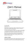
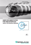
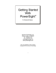
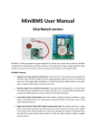
PROCESS AUTOMATION
PS3500 N+1
REDUNDANT POWER SUPPLY
INSTALLATION & OPERATION MANUAL
PS3500 N+1 Redundant Power Supply
Contents
1
2
Introduction .................................................................................................................. 2
Instructions ................................................................................................................... 3
2.1 Intended use.......................................................................................................... 4
2.2 Product label.......................................................................................................... 4
2.3 Mounting................................................................................................................ 5
3 Specifications ............................................................................................................... 5
3.1 Power supply module specifications...................................................................... 5
3.2 System specifications ............................................................................................ 6
3.3 Dimensions............................................................................................................ 8
4 Temperature considerations ....................................................................................... 9
4.1 Convection cooling ................................................................................................ 9
4.2 Forced cooling ..................................................................................................... 10
4.3 Clearances .......................................................................................................... 10
5 Technical concept .......................................................................................................11
5.1 N+1 redundancy ...................................................................................................11
5.2 Hot swapping........................................................................................................11
5.3 Automatic load-sharing.........................................................................................11
5.4 Variable output voltage.........................................................................................11
5.5 Alarm output .........................................................................................................11
5.6 Internal diagnostics, recovery, and LEDs ............................................................ 12
6 Wiring .......................................................................................................................... 13
6.1 Special conditions of use..................................................................................... 13
6.2 Input supply line .................................................................................................. 13
6.3 Input configurations ............................................................................................. 14
6.4 Output configuration ............................................................................................ 16
6.5 Alarm configuration ............................................................................................. 17
7. Output configurations................................................................................................ 18
8. Operations .................................................................................................................. 19
8.1 Supply line checks ............................................................................................... 19
8.2 Output line checks ............................................................................................... 19
8.3 Alarm lines checks .............................................................................................. 19
8.4 Commissioning .................................................................................................... 19
9 Maintenance & Repair ................................................................................................ 20
10 Troubleshooting ......................................................................................................... 21
11 Special warnings! ....................................................................................................... 22
12 Notes ........................................................................................................................... 23
Subject to modifications
www.pepperl-fuchs.com
Copyright Pepperl+Fuchs
USA: +1 330 486 0002
Germany: +49 621 776 2222
Singapore: +65 6779 9091
1
PS3500 N+1 Redundant Power Supply
1
Introduction
This manual applies to the Pepperl+Fuchs PS3500 system that consists of the products
shown in Table 1:
Model number
Description
PS3500-PM-1.24.15
N+1 power supply module, 24 V DC @ 15 A
PS3500-TB-3
Backplane for three power modules and one diagnostic module
PS3500-TB-6
Backplane for six power modules and one diagnostic module
Table 1. PS3500 series product range
The manual assumes that the user has technical knowledge of and experience with power
supply systems, explosion protection, as well as planning and installing power systems. It
does not provide an introduction to power systems or explosion protection for inexperienced
users. The content of this manual applies in conjunction with the respective data sheets,
Declaration of Conformity and Certificate of Compliance. For further information please
refer to the Pepperl+Fuchs "Wiring and Installation Guide."
Substantial amounts of voltage, current and power are provided by the supply. Read this
manual carefully before installation and operation to avoid risk of damage, failures, or
personal injury. Take great care on input and output supply lines to protect from the effects
of short circuits and provide the required ground connections.
2
Subject to modifications
www.pepperl-fuchs.com
Copyright Pepperl+Fuchs
USA: +1 330 486 0002
Germany: +49 621 776 2222
Singapore: +65 6779 9091
PS3500 N+1 Redundant Power Supply
2
Instructions
2.1 Intended use
Warning
The PS3500 product range may be installed in Zone 2 or Class I/Division 2
hazardous areas. Type of protection is Ex nA nC (non-arcing, sealed device)
for Zone 2 Gas Groups IIC, and non-incendive for use in Class I Division 2
Gas Groups A, B, C, and D. Please consult local electrical codes for hazardous
location installation guidelines.
NOTE: This equipment is suitable for use in Class I, Division 2; Groups A, B, C, D and
Class I, Zone 2; Group IIC or nonhazardous locations only.
The Declaration of Conformity, Certificate of Compliance and data sheets are considered
as an integral part of this user manual. The data sheets contain the electrical data of the
Declaration of Conformity and the Certificate of Compliance. Laws and/or regulations
governing the use or intended use must be observed.
The PS3500 products are only approved for proper professional use in accordance with
the intended purposes. Improper handling will void any claim made under the warranty as
well as any manufacturer’s liability. The PS3500 system can only be operated by trained
professionals in accordance with this manual.
2.2 Product label
For proper identification and operation, examine the system model number nameplate to
identify the appropriate approvals, area classification, and type as noted in Figure 1:
Twinsburg, OH 44087 USA / www.pepperl-fuchs.com
P S 3500-P M-1.24.15
Part No. 913919
Input: 90...250VAC
44...66Hz
90...300VDC
6.5A max
Output: 22.5...30VDC
15A
II 3 G Ex nA nC IIC T4 Gc
12ATEX1103387X
IECEx UL 13.0082X
4KM0
Certified to UL STD 508
Certified to ANSI/ISA STD 12.12.01
Certified to CSA STD C22.2 No. 107.1
Certified to CSA STD C22.2 No. 213
Class l, Division 2,
Groups A, B, C, D, T4
Class l, Zone 2,
Groups IIC, T4
Industrial Control Equipment for use in Hazardous Locations
WA R NING - DO NOT SEPARATE WHEN ENERGIZED
UNLESS AREA IS KNOWN TO BE NONHAZARDOUS
AV E R T IS S E ME NT - RISQUE D’EXPLOSION.
NEPAS DEBRANCHER TANT QUE LE CIRCUIT EST
SOUS TENSION, A MOINS QU’IL NE S’AGISSE D’UN
EMPLACEMENT NON DANGEREUX
-25°C
Tamb
45 °C Type 1 (70°C derated)
WARNING - HOT SURFACE - RISK OF BURN
Avertissement - surface chaude - risk de brûlures
See Manual for operating instructions
Figure 1. Power Supply Module
WARNING
AVERTISSEMENT
EXPLOSION HAZARD - DO NOT SEPARATE WHEN ENERGIZED RISQUE D’E XPLOSION - NEPAS DEBRANCHER TANT QUE LE CIRCUIT EST SOUS
TENSION, A MOINS QU’IL NE S’AGISSE D’UN EMPLACEMENT NON DANGEREUX
UNLESS AREA IS KNOWN TO BE NONHAZARDOUS
4KM0
SURFACE C HAUDE - RISK DE BRÛLURES
HOT SURFACE - RISK OF BURN
-25°C Tamb 70 °C Type 1
RISK OF ELECTRIC SHOCK - MORE THAN ONE
Input: 90...250VAC
DISCONNECT SWITCH MAY BE REQUIRED TO
Industrial Control Equipment
44...66Hz
DE-ENERGIZE THE EQUIPMENT BEFORE SERVICING
for
use
in
Hazardous
Locations
90...300VDC
CET EQUIPEMENT RENFERME PLUSIEURS CIRCUITS
6.5A max per slot
See Manual for operating instructions
SOUS TENSION. VOIR LE SCHEMA.
CAUTION
AVERTISSEMENT
II 3 G Ex nA IIC T4 Gc
12ATEX1103387X
IECEx UL 13.0082X
Certified to UL STD 508
Certified to ANSI/ISA STD 12.12.01
Certified to CSA STD C22.2 No. 107.1
Certified to CSA STD C22.2 No. 213
Class l, Division 2,
Groups A,B,C,D, T4
Class l, Zone 2,
Groups IIC, T4
Figure 2. Backplane
Subject to modifications
www.pepperl-fuchs.com
Copyright Pepperl+Fuchs
USA: +1 330 486 0002
Germany: +49 621 776 2222
Singapore: +65 6779 9091
3
PS3500 N+1 Redundant Power Supply
2.3 Mounting
2.3.1 Mounting PS3500 backplanes (termination boards) PS3500-TB-*
The PS3500 backplanes are designed for protection class IP20 in accordance with EN 60529 and
must be protected against adverse ambient conditions such as water or dirt ingress.
The backplane chassis is mounted on a flat metal sheet plate or on two properly spaced rails. Drill
four 5 mm (0.2") DIA holes and tap them 6 MA (or 1/4" NC). Insert the top and bottom screws but
leave a gap of approximately 5 mm (0.2") between the screw heads and mounting surface. Slide
the chassis through the keyed holes and hang it firmly on the screw heads. Proceed to tighten all
the screws.
2.3.2 Mounting PS3500-PM-1.24.15 power modules
The housing of PS3500-PM-1.24.15 meets the degree of protection class IP 20. It is intended for
mounting on the PS3500 backplane PS3500-TB-*.
To install a new module on the backplane proceed as follows:
1.
Carefully center and mate the plug and connector on the back of the power module to the
backplane; then press firmly on the module.
2. With a screwdriver, screw in the top and bottom mounting screw on the power module to
secure the module in the slot.
3. The modules are hot swappable; they can be replaced without shutting down the system. See
Section 5.2, Hot swapping.
4
Subject to modifications
www.pepperl-fuchs.com
Copyright Pepperl+Fuchs
USA: +1 330 486 0002
Germany: +49 621 776 2222
Singapore: +65 6779 9091
PS3500 N+1 Redundant Power Supply
3
Specifications
PS3500 has a wall-mount, multi-slot backplane accepting hot swappable plug-in power
converter modules that provides an isolated output at 24 V DC nominal.
Each power module has an individually isolated input port accepting either AC or DC that
provides inrush current limiting and power factor control. The output port is completely
isolated from the input and provides up to 15 A per module at a nominal 24 V DC
(adjustable 22.5 to 30 V from chassis mounted trimmer) with a load sharing configuration
for paralleled output operation. Input and output lines can be wired independently or in
parallel providing N+1 redundant structures.
System configuration is obtained by wiring and configuration DIP switches on the various
backplane slots leaving power modules interchangeable and easily swappable under load.
All relevant failures in the modules are detected and signaled by individual LEDs and alarm
relays providing a flexible combination of redundancy, fault tolerance, and automatic fault
detection ideally suited to critical applications.
Full compliance to the EU directives for EMC and low-voltage equipment ensure minimum
emissions and high immunity in harsh environments. High conversion efficiency normally permits
natural convection cooling operation eliminating cooling fans for most application requirements.
3.1 Power supply module specifications
Mechanical specifications
Dimensions
(134 mm x 62 mm x 268 mm) 5.3” x 2.5” x 10.6”
Input
Voltage
90…250 V AC ±10%; 90...300 V DC, overvoltage category II
Input current
Max. 6.5 A
Efficiency
Up to 91%
Inrush current
< 50 A peak for 50 μs
Power factor
> 0.97, 50...100% load
Output
Voltage
24 V DC +/-1%, adjustable between 22.5...30 V
Current
15 A
Fault signal
Relay
Short-circuit current
≤ 20 A
Temperature coefficient
±0.01% per °C max
Input regulation
< 100 mV ( 90 ... 250 V AC ; 90 ... 300 V DC )
50 V/0.6 A or 30 V/1 A DC
Load regulation
<100 mV (0...15 A output load)
Turn-on/turn-off voltage transient
200 ms to final value (no over/under shoot)
Ripple
35 mV rms (< 100 mV pp)
Response time
Min. hold-up time: ≥ 25 ms at nominal input voltage & output load
Indicators/settings
Display elements
LED Power, green: power on
LED Fault, red: fault indication
LED Alarm, red: module shut-down
Table 2. Power supply module specifications
Subject to modifications
www.pepperl-fuchs.com
Copyright Pepperl+Fuchs
USA: +1 330 486 0002
Germany: +49 621 776 2222
Singapore: +65 6779 9091
5
PS3500 N+1 Redundant Power Supply
3.2 System specifications
Electrical isolation
Input/output
4.25 kV DC
Input/ground
2.12 kV DC
Output/ground
2.12 kV DC
3.0 kV AC
1.5 kV AC
1.5 kV AC
Ambient conditions
Ambient temperature
-25…+45 °C derated: 0.4 A/°C , (from 45...70 °C)
Altitude
Installation is 2000 m or less
Polution degree
Polution degree 2 or 1
Storage temperature
-40…+85 °C
Shock resistance
15 g, 11 ms
Vibration resistance
1 g, 58...150 Hz
Relative humidity
< 95 % non condensing
Mechanical specification
Protection degree
IP20
Weight
Approximately 1.8 kg (4.125 lbs)
Directive conformity
Electromagnetic compatibility
Directive 2004/108/EC
EN 61326-1:2006
EN 61000 sections 4-2, 4-4, and 4-6
EN 55011
Conformity
6
Electrical isolation
IEC 61131-2
Electromagnetic compatibility
NE 21
Protection degree
EN 60529
Shock resistance
EN 60068-2-27
Vibration resistance
EN 60068-2-6
Subject to modifications
www.pepperl-fuchs.com
Copyright Pepperl+Fuchs
USA: +1 330 486 0002
Germany: +49 621 776 2222
Singapore: +65 6779 9091
PS3500 N+1 Redundant Power Supply
3.2 System specifications (continued)
Data for application in conjunction
with hazardous areas
Type Examination Certificate
12ATEX1103387X Rev.1
Group, category, type of protection
II3 G Ex nA nC IIC T4 (PS3500-PM)
II3 G Ex nA IIC T4 (PS3500-TB)
Directive conformity
Directive 94/9 EC
EN 60079-0, EN 60079-15, EN 61010-1
International approvals
IECEx approvals
Ex nA nC IIC T4 (PS3500-PM)
Ex nA IIC T4 (PS3500-TB)
IECEx UL 13.0082X
UL Listed
ANSI/ISA 12.12.01-2011
UL 508
CSA C22.2 No. 213-M1987,
CSA C22.2 No. 107.1
Approved for
Class I, Zone 2, Group IIC T4
Class I, Division 2, Groups A, B, C, D, T4
General information
Supplementary information
Statement of Conformity, Declaration of Conformity and
instructions have to be observed where applicable.
For information see www.pepperl-fuchs.com.
Table 3. System specifications
Subject to modifications
www.pepperl-fuchs.com
Copyright Pepperl+Fuchs
USA: +1 330 486 0002
Germany: +49 621 776 2222
Singapore: +65 6779 9091
7
PS3500 N+1 Redundant Power Supply
3.3 Dimensions
mm (in)
272
(10.7)
249
(9.8)
Ø 10
(Ø 0.4)
193
(7.6)
112
(4.4)
486
(19.1)
465
(18.3)
Ø 10
(Ø 0.4)
193
(7.6)
112
(4.4)
193
(7.6)
134
(5.3)
62
(2.5)
134
(5.3)
267
(10.5)
238
(9.4)
78
(3.1)
8
35
(1.4)
Subject to modifications
www.pepperl-fuchs.com
Copyright Pepperl+Fuchs
USA: +1 330 486 0002
Germany: +49 621 776 2222
Singapore: +65 6779 9091
306
(12.0)
PS3500 N+1 Redundant Power Supply
4
Temperature considerations
Temperature accelerates the failure mechanism of every electronic component (Arrhenius
criteria). If the operating temperature is increased by 10 °C from its normal operating range,
-25…+45 °C (-11...+113 °F), its expected life is almost cut in half.
Temperature rise depends on dissipated power density. For the same enclosure volume
more power dissipated produces higher temperature rise. For example, a cabinet 600 x
600 x 2000 mm dissipating 300 W with natural convection cooling produces an internal
temperature rise of 10 °C. This should be regarded as an ideal case.
Identify the worst load/temperature environment that the power supply will encounter and
determine the recommended cooling method.
• Use convection cooling when the supply load/operating temperature is typically in the
lower part of the diagram and free air circulation is ensured.
• Use forced cooling when the supply load/operating temperature is in the upper part
of the diagram for extended periods of time or when a very high system reliability is
required.
PS3500 Temperature Derating
16
100 %
Load Current (A)
14
12
75 %
10
8
50 %
6
4
25 %
2
0
0°
5°
15°
25°
35°
45°
55°
65°
70°
Ambient Temperature (°C)
Figure 3. Recommended load current per module vs. operating temperature
4.1 Convection cooling
Hot components exchange heat with the surrounding air producing a vertically rising hot
air flow. This determines new cool air intake to cool the component in a natural convection
cooling mode, which is controlled by the intake air temperature and flow.
For good convection cooling, install the equipment with an unobstructed vertical flow
of relatively cool (ambient temperature) air entering from the bottom and flow out at
a higher temperature from the top. To avoid excessive temperature build up, do not
stack power dissipating devices vertically in close proximity.
Subject to modifications
www.pepperl-fuchs.com
Copyright Pepperl+Fuchs
USA: +1 330 486 0002
Germany: +49 621 776 2222
Singapore: +65 6779 9091
9
PS3500 N+1 Redundant Power Supply
4.2 Forced cooling
Forced cooling is obtained by using suitable fans. Fans generate a strong air flow that
removes heat from the power generating equipment. Use two (PS3500-TB-3) or four
(PS3500-TB-6) 120 mm, 100 m3/h, brushless, long-life fans operated from the output bus
at 24 V DC (e.g., PAPST type) installed immediately below the backplanes and blowing air
up against the bottom of the power modules. Make sure to allow relatively free airflow below
the fans and above the supply rack.
4.3 Clearances
For clearances, we would recommend 1.25” from the sides of the power supplies, and 5”
from the top and bottom when oriented in the standard horizontal position, for convection
cooling. If using forced air convection cooling, this may be reduced some. This assumes
that below the backplane is not another source of heat.
10
Subject to modifications
www.pepperl-fuchs.com
Copyright Pepperl+Fuchs
USA: +1 330 486 0002
Germany: +49 621 776 2222
Singapore: +65 6779 9091
PS3500 N+1 Redundant Power Supply
5
Technical concept
The power supply system consists of two different backplanes (3 and 6 slots) and the
power supply module. The key features of the system are:
•
•
•
•
•
•
•
•
•
Nominal output 24 V/15 A per module
Nominal input of 90 to 250 V AC/90 to 300 V DC per module
N+1 redundancy
Automatic load-sharing
High efficiency (up to 91%)
Fanless
Module output voltage is adjustable at the backplane from 22.5 V to 30 V
Basic module failure alarming via relay contact (normally open/close configurable)
Redundancy on supply line
5.1 N+1 redundancy
N+1 redundancy is based on the fact, that the maximum drawn current is lower than the
maximum current provided by the overall number of modules minus one. Based on the
backplane size, N can be any number between 1 and 5.
5.2 Hot swapping
Hot swapping allows replacement of a module under power without any visible functional
impact on the output side. Hot swapping is allowed only in an environment where no
hazardous materials are present. The hot swapping feature is not permitted in a Class I/
Div 2 area or Zone 2 area unless under a hot permit.
5.3 Automatic load-sharing
The power supply modules implement a real load-sharing function; all modules supply the
same amount of current. The tolerance for the current difference between the modules
should be within a range of ±1.5 A.
5.4 Variable output voltage
The factory default output voltage is 24 V. The output voltage is adjustable in a range from
22.5 V to 30 V for each module by using a potentiometer. Inserted modules can be easily
adjusted with a screwdriver during setup. Potentiometers are accessible on the adjacent
backplane slot making the voltage setting tamper proof during operation.
5.5 Alarm output
Each power module has its own alarm monitoring circuit that controls a relay for a common
failure output signal. It can be configured normally open or normally closed using the
terminal blocks on the backplane.
Subject to modifications
www.pepperl-fuchs.com
Copyright Pepperl+Fuchs
USA: +1 330 486 0002
Germany: +49 621 776 2222
Singapore: +65 6779 9091
11
PS3500 N+1 Redundant Power Supply
5.6 Internal diagnostics, recovery, and LEDs
Overvoltage (OV), overcurrent (OC) and overheat (OHT) conditions lead to an output
shutdown of the unit. Also, they create an alarm signal at the internal relay. Undervoltage
(UV) creates an alarm, but does not shutdown the unit.
During shutdown mode, the unit continuously checks for the actual failure condition to go
away. If that is the case, the unit would go back to normal operation. However, this behavior
must not impact the remaining running units in an N+1 redundant system.
There are three LEDs:
• Power good (green)
• Fault (red)
• Alarm (red)
12
Subject to modifications
www.pepperl-fuchs.com
Copyright Pepperl+Fuchs
USA: +1 330 486 0002
Germany: +49 621 776 2222
Singapore: +65 6779 9091
PS3500 N+1 Redundant Power Supply
6
Wiring
The PS3500 system has separate input/output terminal blocks for simple configuration.
Connect ground terminals to the mains ground, otherwise lethal voltages
may occur.
Warning
Permanent power module damage will result in case of input voltage
overload.
6.1 Special conditions of use
1.
2.
3.
4.
5.
6.
7.
8.
9.
10.
11.
12.
To be installed in an end-use ATEX approved system, providing fire, impact, grounding,
and accessibility protection. The power supply must be installed in an ATEX Certified,
IP54 enclosure. Alternatively, the power can be installed in an IP4X enclosure, having
adequate protection against the entry of solid foreign objects or water capable of
impairing safety.
GND connection on backplane at Mains supply connections is a protective ground
connection. The wire guage should be at least the same as what is used for the mains
power feed.
For any hazardous locations (Class I/Div 2, Zone 2) the PS3500 system must be
installed in a locked enclosure.
Power supply must be secured to system using screws requiring tools for removal.
For indoor use only; not to be subjected to UV exposure from luminaires.
Ambient ratings for operation are -25…+45 °C, derated 0.4 A/°C (from 45...70 °C).
See Figure 3, temperature curve.
The PS3500 system is designed for use in pollution degree 2 environments.
For use with Class 1 conductors or equivalent.
For use with CU conductors or equivalent.
Use 14 AWG conductors or equivalent.
Use conductors rated 75 °C minimum or equivalent.
Alarm relay contacts are rated for 50 VDC or less and are intended to be powered by
DC sources with proper isolation from MAINS.
6.2 Input supply line
Power line voltage is 90...250 V AC ±10% (90...300 V DC). Check supply line voltage to
meet power module supply requirements. Plan for disconnecting capability and over-current
protection by adequately sized fuses or circuit breakers on the lines.
Circuit breakers or fusing shold be 20A or less. connections to 6 poition backplane will
require 2 breakers or fused sources feeding the backplane. Group of 3 slots needs 20A
breaker or less. A single 40A breaker is not allowed.
Ground connection should be made first.
Input Terminals
strip length = 8mm
wire guage max = 4mm sq (10AWG)
tightening torque 0.6 - 0.8Nm
Subject to modifications
www.pepperl-fuchs.com
Copyright Pepperl+Fuchs
USA: +1 330 486 0002
Germany: +49 621 776 2222
Singapore: +65 6779 9091
13
PS3500 N+1 Redundant Power Supply
Output Terminals
strip length = 12mm
wire guage max = 10mm sq (6AWG)
tightening torque 1.2 - 1.5N
Other Terminals
strip length = 7mm
wire guage max = 2.5mm sq (12AWG)
tightening torque 0.5 - 0.6Nm
6.3 Input configurations
6.3.1 Single line input
Use with uninterruptible power systems (UPS) supply or when input line integrity is not
critical, wire per sketch in Figure 4. For DC input, polarity does not matter
N
L
Note!
Each spur to the individual group
of 3 power supplies needs its own 20 A breaker.
Figure 4. Single line input connection
14
Subject to modifications
www.pepperl-fuchs.com
Copyright Pepperl+Fuchs
USA: +1 330 486 0002
Germany: +49 621 776 2222
Singapore: +65 6779 9091
PS3500 N+1 Redundant Power Supply
6.3.2 Dual Line Input
Wire per sketch in Figure 5. For redundant input line configuration, load should not exceed
45 Amps per every 6-position backplane used.
Note!
For this configuration, the phases
of the two supplies should match.
Line 2
Backup
L
N
N
L
Line 1
Primary
Figure 5. Dual line input connection
6.3.3 Independent line connection
Wire per sketch in Figure 6. For independent input line configuration, load should remain
separated.
Line 3
Optional
N
L
Line 2
Backup
N
L
N
L
Line 1
Primary
Note!
For this configuration,
the phases of the
three supplies should match.
Figure 6. Independent multi input line connections
Subject to modifications
www.pepperl-fuchs.com
Copyright Pepperl+Fuchs
USA: +1 330 486 0002
Germany: +49 621 776 2222
Singapore: +65 6779 9091
15
PS3500 N+1 Redundant Power Supply
6.4 Output configuration
Each power module slot has a 6-position DIP switch that enables the various alarm
configurations as well as the load sharing ability of each PS3500 power module. See Table
4 for proper configuration. These configurations are on a per slot basis.
Sx.1
Off
On
x
x
Parallel alarm
Serial alarm+
Load share OFF
Load share ON
Sx.2
On
Off
x
x
Sx.3
Off
On
x
x
Sx.4
Off
On/ Off*
x
x
Sx.5
x
x
Off
On
Sx.6
x
x
Off
On
*Any slot not having a module should have DIP switch #4 turned on
+Slot #1, S1.1 and S1.2 are in parallel therefore either one can be on.
Table 4. Alarm/load sharing configuration
6.4.1 Independent outputs
Use for separate output applications; wire per Figure 7.
+ Out 1
+ Out 2
+ Out 3
+ Out 4
+ Out 5
+ Out 6
Figure 7. Independent output lines
6.4.2 Common outputs
Use for bus connected output or redundant configurations; wire per Figure 8. Refer to Table
4 for load share DIP switch configuration. For multi backplane parallel operation, extend
load sharing connections at terminals 5 and 6 to the next backplane.
NOTE: A separate bus is required for loads > 45 A.
Load Sharing
+
-
Figure 8. Bus connected output or redundant configurations
16
Subject to modifications
www.pepperl-fuchs.com
Copyright Pepperl+Fuchs
USA: +1 330 486 0002
Germany: +49 621 776 2222
Singapore: +65 6779 9091
PS3500 N+1 Redundant Power Supply
6.5 Alarm configuration
6.5.1 Parallel alarm
Connect in parallel, as per Figure 9, the normally closed (N.C.) alarm contacts on all power
modules, and refer to Table 4 for parallel alarm DIP switch configuration. When any specific
relay on a module deenergizes under alarm condition, including power off, the circuit will
close and actuate an alarm (at terminals 1-2 of the alarm terminal block). Pulling a power
module out of the backplane will not actuate an alarm.
1
NC
2
1
2
3
NOTE: Alarm relay # 3 shown in alarm position
Figure 9. Parallel alarm
6.5.2 Serial alarm
Connect in series, as per Figure 10, the normally open (N.O.) alarm contacts on all power
modules and refer to Table 4 for serial alarm DIP switch configuration. When any specific
relay on a module de-energizes under alarm condition, the circuit will open and cause an
alarm. Removing a module will set off the alarm. Any slot without a module will need to
have DIP switch Sx.4 turned on.
2
NO
3
1
2
3
NOTE: Alarm relay # 3 shown in alarm position.
NOTE: If serial alarm is used an alarm will occur when
pulling out a module.
Figure 10. Serial alarm connection
Subject to modifications
www.pepperl-fuchs.com
Copyright Pepperl+Fuchs
USA: +1 330 486 0002
Germany: +49 621 776 2222
Singapore: +65 6779 9091
17
PS3500 N+1 Redundant Power Supply
7. Output configurations
Alarm configuration
Module
No module
(empty slot)
Sx
Parallel with
Load Share
OFF
OFF = Open
Sx
Parallel without
Load Share
Serial with
Sx
Sx
Sx
Sx
Load Share
Serial without
Load Share
Note:
Diagnostic Module DIP Switches
When the Diagnostic Module is not in use, all Diagnostic Module port DIP
switches must be set to the "OFF" position.
18
Subject to modifications
www.pepperl-fuchs.com
Copyright Pepperl+Fuchs
USA: +1 330 486 0002
Germany: +49 621 776 2222
Singapore: +65 6779 9091
PS3500 N+1 Redundant Power Supply
8. Operations
Warning
Warning!
Do not plug and power modules on the backplane before checking all the
systems as recommended.
8.1 Supply line checks
1. Grounding conductor to be connected and firmly secured to the GND terminals.
2. Input lines to be protected by appropriately sized fuses or sectioning circuit breakers
(turning them off).
3. Line conductors to be of adequate size and firmly secured with no exposed conductors
risking contacts with the backplane or short circuits.
4. Supply line voltage to meet power module rating. (Check side label.)
8.2 Output line checks
1.
Output polarity to be correct. (Severe damage to the powered equipment might result in
case of reverse polarity powering.)
2. Output voltage value 24 V. Check on side label of power modules.
3. Output conductors to be of adequate size and firmly secured with no exposed risking
contacts with the backplane or short circuits.
4. Load sharing DIP switches configuration are set. (See section 6.4.)
8.3 Alarm lines checks
1.
Alarm circuit to be correctly wired and conductors firmly secured with no exposed
conductors risking contacts with the backplane or short circuits.
2. Alarm DIP switches configuration set. (See section 6.4.)
8.4 Commissioning
1. Pull out all modules from the backplane
2. Disconnect load on the 24 V output bus and switch the input mains ON.
3. Plug one of the PS3500 modules in slot 1 of the backplane and validate the output to
be within the limits (for a 24 V nominal output, 23.6 V to 24.24 V).
Factory default for the modules is 24 V +/-1%. If a different output voltage is required (within
the 22.5 V to 28 V range), adjust the potentiometer on the backplane to obtain the desired
output.
4. Repeat step 3, using the same module plugged in the backplane slot 2, 3, etc., and
check the output voltage to be within the limits
5. Turn power off, reconnect the load plug in and tighten all modules on the backplane
with the fixing screws.
6. Turn power ON. Only the green LED should appear (no alarms). If any alarm is
displayed, check mains voltage, module configuration and adjustment. If problem
remains refer to the troubleshooting section.
Subject to modifications
www.pepperl-fuchs.com
Copyright Pepperl+Fuchs
USA: +1 330 486 0002
Germany: +49 621 776 2222
Singapore: +65 6779 9091
19
PS3500 N+1 Redundant Power Supply
9
Maintenance & Repair
1.
Supply systems do not require special maintenance except normal periodic functional
checks and cleaning.
2. Keep power modules air inlets and outlets free from dust or particles that may prevent
free air circulation through the cabinet and in the enclosure. Accumulation of dust on
heat dissipating surface limits heat exchange with the surrounding air reducing heatsinking capabilities.
3. Periodically (every year) check and record the output voltage value to capture any longterm deviation.
4. PS3500 power supply products operated in conjunction with hazardous areas must not be
modified. If there is a defect, the product must always be replaced. Defective housing parts
must be replaced by original parts only. For detailed information please refer to the respective
data sheet. Tasks for eliminating malfunctions must be performed only by specialists who are
specially trained and authorized for the task.
Contact customer service for an RMA (return merchandise authorization). Returns for
repair should be sent to:
Pepperl+Fuchs, Inc.
1600 Enterprise Pkwy.
Twinsburg, OH 44087-2245
20
Subject to modifications
www.pepperl-fuchs.com
Copyright Pepperl+Fuchs
USA: +1 330 486 0002
Germany: +49 621 776 2222
Singapore: +65 6779 9091
PS3500 N+1 Redundant Power Supply
10 Troubleshooting
Error condition
Corrective action
Low/high output voltage
Using a voltage meter:
• Measure the output voltage to identify error type.
• Measure input voltage to ensure the voltage range is
within proper limits.
• If output voltage is low, measure output current to
ensure that it does not exceed 15 A per module.
• If modules are load sharing, make sure DIP switches
are configured properly and that each of the modules
is supplying the same voltage.
• If error persists, module needs to be replaced.
Over-voltage shutdown
Identify faulty module using a voltage meter:
• Measure input voltage to ensure the voltage range is
within the proper limit.
• Unplug the module and then plug back in.
• If error persists, module needs replaced.
Unequal load sharing
Using a voltage meter:
• Measure input voltage to ensure proper range.
• Measure the output voltage of each module, and if
needed, adjust voltage potentiometer on backplane so
that each module supplies the same voltage.
• If problem persists, replace module.
Alarm LED illuminated
Check module alarm configuration.
• Ensure DIP switches are set properly for serial or
parallel alarm.
• Repeat first three steps (above) for previously
mentioned error conditions.
• If alarm persists, replace module.
Subject to modifications
www.pepperl-fuchs.com
Copyright Pepperl+Fuchs
USA: +1 330 486 0002
Germany: +49 621 776 2222
Singapore: +65 6779 9091
21
PS3500 N+1 Redundant Power Supply
11 Special warnings!
Warning
1. Warning - Explosion hazard - do not disconnect equipment unless
power has been switched off or the area is known to be non-hazardous.
Avertissement – Risque d’explosion - avant de déconnecter
l’equipement, couper le courant ou s’assurer que l’emplacement est
désigné non dangereux.
2. Exposure to some chemicals may degrade the sealing properties of materials
used in the following devices:
Panasonic DS series sealed relay (The case is thermal setting PBT with an epoxy
resin encapsulant.)
Warning – Substitution of the following components may impair suitability for
Division 2:
• Reference designation:
• Description:
• Type of protection:
RL1
Relay
Sealed contacts
Avertissement - L’exposition à certains produits chimiques mai dégrader la
fermeture des propriétés des matériaux utilisés dans les appareils suivants.
Panasonic DS series sealed relay (The case is thermal setting PBT with an epoxy
resin encapsulant.)
Avertissement – Risque d’explosion – la substitution se composants peut render
ce matériel inacceptable pour les emplacements de Classe 1, Division 2:
• Reference designation:
• Description:
• Type of protection:
RL1
Relay
Sealed contacts
3. Warning - Explosion hazard - do not remove fuses or plug-in modules (as
applicable) unless power has been disconnected or the area is known to be free
of ignitable concentrations of flammable gases or vapors.
Avertissement – Risque d’explosion – Ne pas retirer les fusibles ou les plugin modules (selon le cas) que si le pouvoir a été déconnecté ou la région est
connue pour être exempts de inflammable concentrations de gaz inflammables
ou vapeurs.
22
Subject to modifications
www.pepperl-fuchs.com
Copyright Pepperl+Fuchs
USA: +1 330 486 0002
Germany: +49 621 776 2222
Singapore: +65 6779 9091
PS3500 N+1 Redundant Power Supply
12 Notes
Subject to modifications
www.pepperl-fuchs.com
Copyright Pepperl+Fuchs
USA: +1 330 486 0002
Germany: +49 621 776 2222
Singapore: +65 6779 9091
23
PS3500 N+1 Redundant Power Supply
12 Notes
24
Subject to modifications
www.pepperl-fuchs.com
Copyright Pepperl+Fuchs
USA: +1 330 486 0002
Germany: +49 621 776 2222
Singapore: +65 6779 9091
PROCESS AUTOMATION –
PROTECTING YOUR PROCESS
For over a half century, Pepperl+Fuchs has provided new concepts for the world of process automation. Our company
sets standards in quality and innovative technology. We develop, produce and distribute electronic interface modules,
Human-Machine Interfaces and hazardous location protection equipment on a global scale, meeting the most demanding needs of industry. Resulting from our world-wide presence and our high flexibility in production and customer service,
we are able to offer complete individual solutions – wherever and whenever you need us. We are the recognized experts in our
technologies – Pepperl+Fuchs has earned a strong reputation by supplying the world’s largest process industry companies
with the broadest line of proven components for a diverse range of applications.
6
1
5
3
7
4
2
8
3
1
2
Worldwide/German Headquarters
Pepperl+Fuchs GmbH
Mannheim · Germany
Tel. +49 621 776 2222
E-Mail: [email protected]
Asia Pacific Headquarters
Pepperl+Fuchs PTE Ltd.
Singapore
Company Registration No. 199003130E
Tel. +65 6779 9091
E-Mail: [email protected]
Central/Western Europe &
Africa Headquarters
Pepperl+Fuchs N.V.
Schoten/Antwerp · Belgium
Tel. +32 3 6442500
E-Mail: [email protected]
6
Northern Europe Headquarters
Pepperl+Fuchs GB Ldt.
Oldham · England
Tel. +44 161 6336431
E-Mail: [email protected]
4
Middle East Headquarters
Pepperl+Fuchs M.E (FZE)
Dubai · UAE
Tel. +971 4 883 8378
E-Mail: [email protected]
7
Southern/Eastern Europe Headquarters
Pepperl+Fuchs Elcon srl
Sulbiate · Italy
Tel. +39 039 62921
E-Mail: [email protected]
5
North/Central America Headquarters
Pepperl+Fuchs Inc.
Twinsburg · Ohio · USA
Tel. +1 330 486 0002
E-Mail: [email protected]
8
South America Headquarters
Pepperl+Fuchs Ltda.
São Bernado do Campo · SP · Brazil
Tel. +55 11 4341 8448
E-Mail: [email protected]
www.pepperl-fuchs.com
Subject to modifications • © 2013 PEPPERL+FUCHS, INC. • Printed in USA • Part No. 912759 Drawing No. DOCT-B001EENG 03/15