1
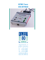
BITBUS Tracer
USB-BITTRACE
Mikrocomputer GmbH&Co. KG
Theaterplatz 9
52062 Aachen
G e r m a n y
Ph. +49-241-48410
Fax +49-241-48480
[email protected]
w w w. e l z e t 8 0 . d e
Inhalt
BITBUS-TRACER "USB-BITTRACE" ..................................................................................3
1 Overview .................................................................................................................3
1.1 Start..................................................................................................................4
2 User interface...........................................................................................................4
2.1 Main-Menu .......................................................................................................5
Trace modes................................................................................................................8
2.2 Config Trace Menu ..........................................................................................10
2.3 Config Msg-Display Menu ...............................................................................13
2.4 Config LED Display Menu ................................................................................14
3 Hardware ..............................................................................................................15
BITBUS-TRACER "USB-BITTRACE"
BITBUS-TRACER "USB-BITTRACE"
1 Overview
The BITBUS-TRACER helps troubleshooting a BITBUS network. It is linked to the BITBUS
network and listens to all messages that are exchanged on the network. Depending on how
it was configured it buffers all messages or only special messages for an evaluation. The
tracer is operated with a terminal programm using its USB-port which encapsulates a
serial interface.
We suggest to use the terminal program wLGO that can be found on the USB-stick at the
bottom lid of the enclosure.
There are two Sub-D-9 connectors on the top lid to connect the BITBUS under test. You
may also use the screw terminal plugs on the front panel - all BITBUS signals are
interconnected. Signal polarity is irrelevant with BITBUS as it only depends on edges, not
on their polarity.
Tracing can be started and stopped from the serial interface or from the push buttons,
alternatively the trigger input (5..24V) can control tracing. The tracer can be just stopped
(EDGE-Mode) by a trigger signal, or started and stopped again (GATE-Mode). The edge type
can be set by software.
The trigger outputs are set when the tracer has stopped the trace job. The polarity of the
edges can be set by sofware, too.
This document describes the BITBUS-TRACER with software version 1.9.
Please find a USB-stick on the bottom lid containing current drivers, documentation and a
terminal program. The USB socket is electrically neutral, it is just a fixture.
1 Overview
3
1 Overview
1.1 Start
Connect the BITBUS-TRACER to a PC (not to a passive hub!), wait for the green "USB ok"
LED to be lit. Not before then start the terminal program (i.e. wLGO) - virtual ports
are not shown in Windows®' configuration before a device is connected.
Enter h to show the help list in the terminal program.
2 User interface
The user interface has a simple character interface in order to make all functions of the
tracer available to almost any terminal programm.
It is partitioned into a main menu and three submenus. In each menu a help text can be
viewed with "H" or "h" that shows the possible inputs. For changing back to the main menu
"-" has to be entered. In parameter queries the upper case letters, or the first digit of
numbers, are used for selection.
4
2 User interface
BITBUS-TRACER "USB-BITTRACE"
2.1 Main-Menu
2.1.1 Start Trace
Key: A or a
Start trace job (corresponds to the start-button at the front panel).
2.1.2 Stop Trace
Key: O or o
Stop trace job (corresponds to the stop-button at the front panel).
2.1.3 Get status of tracer (running/stopped)
Key: S or s
Display the operating condition of the tracer (corresponds to the trace LED at the front
panel).
2.1.4 Get number of received Msgs
Key: P or p
Display the total number of buffered BITBUS messages.
2.1.5 Get number of available Msgs
Key: G or g
Display the number of BITBUS messages available for output. This value can differ in
TraceForever mode and TraceUntil mode from the total number of buffered messages
because the oldest messages are overwritten during an overflow in the circular buffer.
2.1 Main-Menu
5
2 User interface
2.1.6 Display Msg number #
Key: D or d #
Display buffered header of the BITBUS message. An additional parameter is being queried
that specifies the position of the BITBUS message in the circular buffer
(value range: 0 <= MsgNum <= Available Msgs - 1).
2.1.7 Display next Msg
Key: +
Display buffered header of the next BITBUS message in the circular buffer.
2.1.8 Display previous Msg
Key: –
Display buffered header of the previous BITBUS message in the circular buffer.
2.1.9 Display data of current msg (dump)
Key: I or i
Shows the data field content of the active message in form of a memory excerpt.
2.1.10 Display data of current msg (formatted)
Key: F or f
Shows the datafield content of the active message formatted with a previously entered
format string (the format string can be specified in the menu - "Config Msg-Display").
6
2.1 Main-Menu
BITBUS-TRACER "USB-BITTRACE"
2.1.11 Display next #1 Msgs beginning at number #2
Key: R or r
Displays several messages successively. As additional parameters the position of the first
message and the number of messages for display are to be entered. It is also necessary to
enter whether the messages should be displayed with or without data and formatted or
unformatted.
This function will be used for saving the buffer contents later on (e.g. with the logfile
function of the terminal programm LGO).
2.1.12 Statistics counter #1 for node #2
Key: C or c
Display of a value from statistic analysis. The desired value is queried as parameter und
possibly the node number for which the value is output.
The following statistical counters are available:
PROGRESS total number of buffered messages
CRC
number of CRC errors
ABORT
number of ABORT errors
OPEN
number of OPEN procedures (node dependent)
CLOSE
number of CLOSE procedures (node dependent)
MSG
number of messages (node dependent)
DATA
number of data bytes (node dependent)
2.1.13 Config Tracer...
Key: T or t
Changes to the Config-Trace-Menu. Modification is only possible when the tracer is
inactive.
2.1 Main-Menu
7
2 User interface
2.1.14 Config Msg-Display...
Key: M or m
Changes to the Config Msg-Display Menu. See 2.3
2.1.15 Config 7SEG-LED-Display...
Key: L or l
Switches to the Config LED-Display Menu. See 2.4
Trace modes
There are basically three trace modes:
FILLBUFFER
never buffers more messages than fit into the buffer.
FOREVER
buffers all messages until a stop is entered (wenn the buffer
is full the oldest messages will be overwritten).
UNTIL
buffers all messages until a message, specified by further
parameters, comes in.
A stop command from the user interface or pushing the stop button at the front panel will
stop the trace job immediately in any mode. The same thing happens if the stop is caused
by the trigger input.
8
Trace modes
BITBUS-TRACER "USB-BITTRACE"
In UNTIL mode further parameters have to be entered to specify the stop criterion.
ADDRESS
All messages are buffered until a number of messages have
been received by a specific BITBUS node address.
Possible node numbers:
1...250
FLAG
All messages are buffered until a number of specific message
types have been received.
Possible message types are:
ERR
I
Information-Frame
SNRM
Set Normal Response Mode
FRMR
Frame Reject
UA
Unnumbered Acknowledge
DISC
Disconnect
RR
Receiver Ready
RNR
Receiver not Ready
ERR
All messages are buffered until a number of
specific errors have occurred.
Mögliche Fehler sind:
CRC
ABORT
The count of these specified messages that will stop the trace job has to be entered and
whether the counter should be reset by an intermediately received information frame.
Trace modes
9
Trace modes
2.2 Config Trace Menu
2.2.1 Config trace mode
Key: T or t
Configuration of the trace mode.
2.2.2 Config filter mode
Key: F or f
Configuration of the filter mode.
The following filters are available:
ADDRESS Only for messages for a specific BITBUS node are buffered.
Possible node numbers: 1...250.
FLAG
Only messages of a specific message type are buffered. (for a list of
available selections see "Config trace - UNTIL - FLAG").
ERR
Only errors are buffered (for a list of available selections see
"Config trace - UNTIL - ERR").
NO FILTER Deactivates message filtering.
10
2.2 Config Trace Menu
BITBUS-TRACER "USB-BITTRACE"
2.2.3 Config trigger
Key: I or i
Configuration of the trigger input or output respectively.
The trigger inputs can be operated in two different modes:
EDGE
Trace job will be stopped by a specific edge at the trigger input
GATE
Trace job will be started and stopped by a specific signal level at
the trigger input
NO
Deactivate trigger inputs
When the trace job is stopped, an edge is generated at the trigger output which can be
used to control an external device.
The polarity of the trigger input and output can be configured in software:
Edge type:
POSITIVE
The input responds to a positive edge or signal level. The output
generates a positive edge when the trace job is stopped.
NEGATIVE The input responds to a negative edge or signal level. The output
generates a negative edge when the trace job is stopped
2.2 Config Trace Menu
11
Trace modes
Behaviour of the trigger inputs with the possible configuration and signal courses:
Trigger input:
Mode: Positive edge
Mode: Positive level
Mode: Negative edge
Mode: Negative level
Behaviour of the trigger output at the end of a trace:
Trigger output:
Mode: Positive
Mode: Negative
2.2.4 Set Bitbus speed
Key: B or b
The usual BITBUS speeds (62.5, 375, 750, 1500 kbit/s) are available, they are selected by
entering the first digit. The setting will be valid after restart.
12
2.2 Config Trace Menu
BITBUS-TRACER "USB-BITTRACE"
2.3 Config Msg-Display Menu
2.3.1 Set format string
Key: F or f
Input of the format string for formatted output of the message datafield. The format string
has to be entered like a standard C-format-string.
In addition to the formats available format information there are two
extensions:
b
For size information b (for byte) is available. In this case only one
byte of the message will be extracted and converted. With "%bd"
a one byte decimal number will be put out.
<
With "<" a specific number of bytes of a message can be left out
on not be converted. So "%10 means that the next 10 bytes of a
message will not be considered at the conversion.
2.3 Config Msg-Display Menu
13
Trace modes
2.4 Config LED Display Menu
Configuration of the LED-Display.
All statistic counters can be displayed at the LED-Display. The first character is always a
letter that represents the displayed value.
2.4.1 Progress
Key: P or p
The counter of all buffered messages will be displayed.
The first character displayed is a "P".
2.4.2 Crc
Key: C or c
The counter of CRC errors will be displayed.
The first character displayed is a "C".
2.4.3 Abort
Key: A or a
The counter of ABORT errors will be displayed.
The first character displayed is an "A".
2.4.4 Open
Key: O or o
The OPEN-counter for a specific node will be displayed.
The first character displayed is an "o".
14
2.4 Config LED Display Menu
BITBUS-TRACER "USB-BITTRACE"
2.4.5 Close
Key: L or l
The CLOSE-counter for a specific node will be displayed.
The first character displayed is an "L".
2.4.6 Msg
Key: M or m
The message counter for a specific node will be displayed.
The first character displayed is an "L".
2.4.7 Data
Key: D or d
The data counter for a specific node will be displayed.
The first character displayed is a "d".
3 Hardware
3.1 USB connection
The serial interface works with 19200 baud, 8 bit, no parity, 1 stop bit. It is presented as a
USB port at the top lid by means of a serial to USB converter as newer notebooks do not
offer an RS232 port anymore. To start the tracer, please connect USB to the PC first, then
start the terminal program. After the PC has recognized the new device, the green LED of
USB-BITTRACE indicates that the terminal program would show the newly added virtual
serial line in its settings. Enter h for help to test the connection.
The USB port is not isolated. Current consumption is below 200mA.
3 Hardware
15
3 Hardware
3.2 BITBUS Inputs
The BITBUS inputs are optoisolated. Caution: The shield (hood) of the DB9 connectors are
connected to the shield of the USB connector and hence to PC ground. If your BITBUS line
needs to be isolated, isolate the cable shield inside the connector.
3.3 Trigger
The optoisolated trigger input has a built-in series resistor which allows application of
voltages between 5V and 24V, for instance from a PLC output or a switch.
The trigger output is a blank optoisolator output of an SFH6186-5X001 with high current
transfer ratio (CTR) but low current capacity. It can be used to drive voltage inputs (like a
scope) or 24V controller inputs, but no relays etc.
Caution with trigger inputs and outputs: Excessive currents will destroy the optoisolators.
16
3 Hardware