1
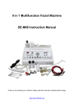
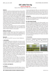
A CONTROL SYSTEM FOR BEPC RING INJECTION
POWER SUPPLIES
H.Zhang, R.Zhang, S.Lu, IHEP, Beijing, China
ABSTRACT
A control system for controlling BEPC ring injection
power supplies has been built. This control system is
characterized by using Intel Bitbus network and manmachine graphic interactive interface. It is based on a
Intel industrial PC with Intel iRMX for windows in it
plus several Bitbus stations. The whole system has been
examined completely and put into operation in May this
year in place of the existing hardware control system.
The new PC-Bitbus computer control system will be
prepared to communicate with main VAX workstation
through Ethernet and to be controlled directly by main
computer X-window as soon as possible.
1 INTRODUCTION
The existing BEPC ring injection supply control
system was designed in 1985 and has run reliablly since
1987. It was a standalone hardware system due to the
need for whole BEPC VAX-VCC-CAMAC computer
control system. Main disturbing sources like Kickers
were separated from the main system. From the
development point of view, It’s time to substitute the
hardware system by a computer system after such a long
observation and operation experiences. We decided to
use an Intel Bitbus network protocol and put controller
stations as close to the supplies as possible in order to
get better control quality.
2 SYSTEM APPLICATION
The PC-BITBUS system is a complete autonomous
computer control system, it controls over six injection
supplies ---- four Kickers and two Lambersons. They are
located along the ring injection spots for positron and
electron injections respectively. The control system
features in Bitbus, MS-Windows and Intel industrial PC
302i, which functions as a backbone of the distributed
real time control system and acts as a development
system for whole control system.
fig. 1 system hardware architecture
IRMX for windows of 32 bit real time, multitasking
operating system installed in PC makes MS-Windows
and MS-DOS as one of its tasks to run. But iRMX for
Windows is a character-oriented system, MS-Windows
has a good, powerful graphic functions with
multiwindow and multitask. We should gain benifits
from combining them for our control requirements. Our
aim has been reached. No other specialized graphic
control software are needed.
Bitbus network adheres to IBM’s HDLC/SDLC
protocol, comprises one primary station and eight
secondary stations with two isolators, see Fig 1.
Bitbus network operates at self-clocked, half-duplex
mode, data transfer speed of 375 Kbps with two
segments, maxmun distance of 300M per segment.
iRMX for Windows communicates with Bitbus
stations through the Bitbus driver developed by
ourselves. Bitbus message frame is 20 bytes long, master
station launchs the order command for Bitbus message
transmission each time. A preconfigured compact real
time multitasking executive iDCX51 has been preloaded
on each Bitbus stations.
MS-Windows DDE router and Library provided by
iRMX for Windows facilitate it to set up a connection
for message transfering to and from MS-Windows.
The key issues for PC-BITBUS computer control
system are how to communicate data between different
working platforms. For examples, between MS-Windows
and iRMX for Windows, between iRMX for windows
and iDCX51 executive on stations. It is pleased that we
solve these difficulties without seeking for dedicated
software. see Fig. 2.
slot of PC. Two shielded pairs come from PC to RCX
900 isolation modules for Bitbus network isolation and
transient protection. Second level is 8 Bitbus secondary
stations. They are grouped near the controlled supplies,
each station installed one of Intel distributed control
modules----iRCB 44/10A BITBUS Digit I/O Remote
Controller Board or iRCB 44/20A BITBUS Analog I/O
Remote Controller Board and/or MULTIMODULE
iSBX 350, They are fixed on HRCX 910/920
Digital/Analog Signal Conditioning and Termination
modules. The third level is supply interface like DAC
units which are put into controlled supplies, in this case
analog reference cables are less than one meter to assure
control stability.
There is a high performance 12 Mhz 8044 controller
on each Intel distributed control board, up to 64 KB
ROM and RAM with jumpers selection are easily
accomodated on the board.
We developed HRCX-910. HRCX-910 has 48 digit
I/O used for iRCB 44/10A and iSBX-350. 13 bits of port
A and port C of iRCB44/10A are output to DAC units
through optical isolators TIL-117, 12bits as digital code,
one bit as clock. Port B picks up status inputs from
supplies. Three ports on Digital MULTIMODULE
iSBX-350 run all in mode 0, on-off control routes to its
port B through relay contacts. HRCX-910, iRCB44/10A
and/or iSBX-350 those are installed on a U-type 19 inchs
wide shelf form a BITBUS station.
HRCX-920 is used for analog termination for iRCB 44/20A. Only 4 analog channels are in use, others of 16
channels are grounded, 2 DAC outputs are used for selftest. Analog isolation devices are BB 3652GJ which
have good isolation electricity capability, better
linearity, low temprature coefficient, high input
impedence, and 5ma output load capability, gain are set
to one, input range is within 0 - 10V with overvoltage
protection. BB 722 isolation power source devices are
worked with BB 3652 in order to get better performance.
Each analog input is truely differenciated. HRCX-920
and iRCB44/20A construct one Bitbus station like
HRCX-910.
4 SYSTEM APPLICATION
SOFTWARE ARCHITECTURE
fig. 2 system application software architecture
3 SYSTEM HARDWARE
ARCHITECTURE
System hardware architecture comprises three parts,
see Fig. 1. Intel PC----80386 25DX AT Bus----is the
heart of the whole system, placed at the central control
room. IPCX 344 as Bitbus master station is plugged in a
The whole application software may be devided into
three levels. Top level is some procedures for control
screen. Middle one is the heart of the whole application
software, it consists of one main program and one small
database with index programs in addition to two
communication packages. Bottom level has a lot of I/O
operations dedicated for defferent Bitbus station needs.
see fig. 2.
Graphic man-machine interface are finished through
MS Visual Basic 3.0 in MS Windows 3.1. VB is a true
object-oriented language, its universal powerful
functions bring us one of farourite graphic programming
tool. We program three pages, one for system control,
two for help and other desplays.
Control page is our main page. On it, there are on-off
buttons which can be clicked to turn on-off supplies,
supplie status desplay which can turn green or red like
indicators, readback analog values which desplay truely
like multi-digital meters, reference analog value setting
inputs which employ several methods like pull-down
menus for trim step selection, keyboard for directly
setting value input, scroll bars for reference trimming.
Pressing standardized button on the screen can have the
supply standardized one time from present value to
maximum, then back to zero, finally loop to original
value. The whole computer screen is devided into two
identical parts used for positron and electron injection
controls respectively.
DDE link implements MS-Windows message passing
to and from iRMX for Windows. Two sides have masterslave relationship, client on iRMX for Windows side,
server on MS-Windows side. The link is established
from client request. Since control parameters change
from time to time at administration of operators, hot
links have to be created for on-off control, analog
reference setting in order to receive changes in control
parameters at any time. As with status signals and analog
requisation values , they would be poked to server at
every five second or so.
Main programs in iRMX for Windows are written in
C, they play a very important role in the whole control
system. There is a database for all controlled signals in
it. As matter of fact, database is a common data access
area for data exchange and search. The database has four
types of data, we usually search data in it using signal id
or data type. Database refreshes every five second or so
under normal condition.
Bitbus driver is also a important one for PCBITBUS control system. Communication package has
been finished under iRMX for Windows with C
language. IPCX-344 is actually a gateway. The two byte
registers (FIFOs) on it provide the path for bytes to move
through the parallel interface. Bytes are read or written
from the registers destinated: FIFO Data Byte and FIFO
Command Byte to carry out data transfer between IBM
PC bus (80386 CPU) and Bitbus (8044 Controller).
Another important task for communication package is
access to RAC task which as part of task 0 provides the
means of invoking iDCX-51 Executive System Services
from tasks on PC extension.
PLM51, ASM 51and others are development tools
for task code run on each BITBUS station with different
functions.
5 QUESTIONS AND SOLUSIONS
New PC-BITBUS computer control system has
commissioned.. We met a big challeage during having
the system examined at the field site, but easy expansion
and flexible configuration for Bitbus distributed control
system bring us a lot of benifits.
Defferent supplies require different control mode took
us a lot of time to find solusions.
We have to move the control task code from stations
to iRMX for Windows platform because of no in-circuit
iCE-5100/044 emulator, no iUP-200A/201A programmer
and no fast enough EEPROM.
ISBX-350 MULTIMODULE board on BITBUS I/O
Remote Controller Board seemed not to work correctly,
iSBX-350 were replaced with iRCB 44/10A.
6 IN THE FUTURE
PC-BITBUS distributed control system will be
supervised by existing X-Window on VAX stationCAMAC system main console from Ethernet complying
with TCP/IP protocol in the next a few months. Network
communication application using Berkeley sockets will
be prepared on MS-Windows 3.1 through VB or on
iRMX for Windows through C.
REFERENCES
[1] IRMX for Windows data books, published by Intel
Corporation, 1991,1992.
[2] ‘Distributed Control module databook’, published
by Intel Corporation, 1988.
[3] ‘BITBUS interface handlers user’s manual’,
published by Intel Corporation, 1987.