1
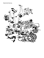
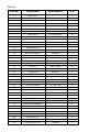
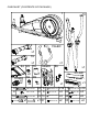
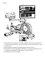
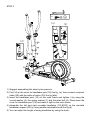
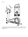
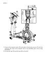
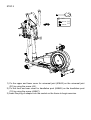
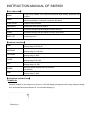
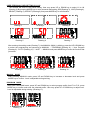
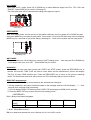
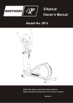
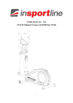
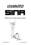
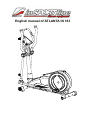
English manual of ATLANTA IN 163
Safety Instructions
• To ensure the best safety of the exerciser, regularly
check it on damages and worn parts.
• If you pass on this exerciser to another person or if
you allow another person to use it, make sure that
that person is familiar with the content and
instructions in these instructions.
• Please note that levers amd other adjustment
mechanisms are not projecting into the area of
movement during the work-out.
• When setting up the exerciser, please make
sure that the exerciser is standing in a stable
way and that any possible unevenness of the
floor is evened out.
• Only one person should use the exerciser at a time.
• Before the first use and regularly make sure that all
screws, bolts and other joints are properly tightened
and firmly seated.
• Before you start your work-out, remove all
sharp-edged objects around the exerciser.
• Only use the exercise for your work-out if it works
flawlessly.
• Any broken, worn or defective part must immediately
be replaced and/or the exerciser must no longer be
used until it has been properly maintained and
repaired.
• Parents and other supervisory persons should be
aware of their responsibility, due to situations which
may arise for which the exerciser has not been
designed and which may occur due to children’s
natural play instinct and interest in experimenting.
• If you do allow children to use this exerciser, be sure
to take into consideration and assess their mental
and physical condition and development, and above
all their temperament. Children should use the
exerciser only under adult supervision and be
instructed on the correct and proper use of the
exerciser. The exerciser is not a toy.
• Make sure there is sufficient free space around the
exerciser when you set it up.
• To avoid possible accidents, do not allow children to
approach the exerciser without supervision, since
they may use it in a way for which it is not intended
due to their natural play instinct and interest in
experimenting.
• Please note that an improper and excessive
work-out may be harmful to your health.
• Always wear appropriate clothing and shoes
which are suitable for your work-out on the
exerciser. The clothes must be designed in a
way so that they will not get caught in any part of
the exerciser during the work-out due to their
form (for example, length). Be sure to wear
appropriate shoes which are suitable for the
work-out, firmly support the feet and which are
provided with a non-slip sole.
• Be sure to consult a physician before you start
any exercise program. He may give you proper
hints and advice with respect to the individual
intensity of stress for you as well as to your
work-out and sensible eating habits.
Important Notes
• Assemble the exerciser as per assembly instructions
and be sure to only use the strucutral parts provided
with the exerciser and designed for it. Prior to the
assembly, make sure the contents of the delivery is
complete by referring to the parts list of the
assembly and operating instructions.
• Be sure to set up the exerciser in a dry and even
place and always protect it from humidity. If you wish
to protect the place particularly against pressure
points, contamination, etc., it is recommended to put
a suitable, non-slip mat under the exerciser.
• The general rule is that exercisers and training
devices are no toys. Therefore, they must only be
used by properly informed or instructed persons.
• Stop your work-out immediately in case of dizziness,
nausea, chest pain or any other physical symptoms. In
case of doubt, consult your physician immediately.
• Children, disabled and hadicapped persons should
use the exercise only under supervision and in
presence of another person who may give support
and useful instructions.
• Be sure that your body parts and those of other
persons are never close to any moving parts of the
exerciser during its use.
• When adjusting the adjustable parts, make sure
they are adjusted properly and note the marked,
maximum adjusting position, for example of the
saddle support, respectively.
• Do not work out immediately after meals!
Exploded drawing
Part List
Part No.
Description
Specification
Q’ty
1
Main frame
2
stabilizer
D76x1.5Tx480L
1
3
carriage bolt
M8x1.25x93L,8.8
4
4
Adjustable foot cap
D76*86
2
5L
Left transfer foot cap
D76*120L
1
5R
Right transfer foot cap
D76*120L
1
6
curve washer
D22xD8.5x1.5T
12
7
spring washer
D15.4*D8.2*2.0T
10
8
domed nut
M8x1.25x15L
4
9
allen bolt
M8x1.25x20L,8.8
8
10
handlebar post
1
11
pedal welding set
2
12L
left swing support
1
12R
right swing support
1
13
front foot cover(out)
100x54x27
2
14
front foot cover(inner)
100x54x24
2
15
round end cap
D1"*17.5L
2
16
allen bolt
M8x1.25x100L,8.8
2
17
left upper foot cover
115x95x43
2
18
nylon nut
M10*1.5*10T
3
19
stabilizer
D76x1.5Tx480L
1
20
carriage bolt
M6*1*45L
4
21L\R
pedal
345x150x45
1
22
cap for bolt
D30*17(M12)
2
23
ladder bolt
M10*1.5*66L
2
24
flat washer
D24*D13.5*2.5T
2
25
round cross screw
ST4.2x1.4x20L
4
26
c ring
S-16(1T)
2
27
electric cable
700L
1
28
sensor cable
700L
1
29
upper computer cable
1000L
1
30
motor
31
bushing
32
pedal bearing welding set
2
33
crank welding set
2
34
pulley
35
poly belt
36L
left chain cover
1
36R
right chain cover
1
37
magnetic system
D274*138L
1
38
right upper foot cover
115x95x43
2
1
1
D29*D11.9*9T
D310x19
1321
PJ6
4
1
1
39
side cap
D36*14
2
40
bolt
M8x1.25x20
4
41
fixed ring
D38*D26.5*7
2
42
round discs
43
bearing
#6004ZZ
2
44
round cross screw
ST4x1.41x15L
24
45
anti-loose nut
3/8"-26UNFx6.5T
2
46
FE flat washer
D30*D10*4.1T
1
47
flat washer
D50*D10*2T
1
48
small spacer
D10*D14*3T
1
49
insert plug
D31.8xD28.5x82L
2
50
flat washer
D20*D11*2T
2
51
plastic flat washer
D50*D10*1.0T
2
52
swing support welding set
53
foam
D30x7Tx550L
2
54
foam
D23x7Tx530L
2
55
mushroom cap
D1 1/4"*45 L
2
56
spring
D4.0xD20x82L
1
57
nylon nut
M6x1.0x6T
4
58
bolt
59
cap for bolt
D28*17(M10)
2
60
flat washer
D26*D21*1.5T
1
61
crank welding set
62
round magnet
M02
1
63
waved washer
D27*D21*0.3T
1
64
computer
SM-7650-71
1
65
right foot cover
80*55*87
2
66
left foot cover
80*50*87
2
67
c ring
S-16(1T)
2
68
waved washer
D21xD16x0.3T
2
69
bearing
#99502ZZ
12
70
idle fixed plate
71
front pedal axle
72L
left handlebar
1
72R
right handlebar
1
73
flat washer
D14xD6.5x0.8T
4
74
idle
D43*25L
1
Hand pulse
WP1007-09B
2
pulse cable
500L
2
76
anti-loose nut
M10*1.25*10T
2
77L
left front chain cover
1
77R
right front chain cover
1
78
upper protective cover
1
79
flat washer
D23*D17*1.2T
4
80
flat washer
D21*D8.5*1.5T
2
75
2
2
M6x1.0x15L
8.8
4
1
1
D15.85x63.2L
2
81
upper universal cover
125*90*39
2
82
lower universal cover
125*90*39
2
83
smaller adjustable knob
D38xM16x1.5xD8x23
2
84
front computer base
380*150*50
1
85
rear computer base
340*150*50
1
86
adaptor
87
round cross screw
ST4x1.41x15L
2
88
insert plug
D71.5*108L
1
89
knob
D40xM6x12L
4
90
round cross screw
ST4*1.41*20L
8
91
round cross screw
ST4x1.41x10.L
2
92
cap for bolt
D35*8
2
93
nylon nut
M8*1.25*8T
2
1
CHECKLIST (CONTENTS OF PACKAGE)
1
10
X1
2
72L&R
X1
19
X1
X1
64 22
78
84&85
86
X1
M12
X2
81&82
X2
X2
3
9
16
59
21L&R
X1
89
M10
X2
M8*1.25*93L
M8*1.25*20L
M8*1.25*100L
x1
X4
6
X4 8
X2 73
X4
x1 87
X1
D22*D8.5*1.5T
M8*1.25*15L
D14*D6.5*0.8T
M5*0.8*10L
X1
X1
X12
7
X4 20
X4 44
X2
93
D15.4*D8.2*2T
M6*1*45L
ST4*15L
M8*1.25*8T
X10
X4
X6
X2
STEP 1
(x4)
B (x4)
M6*1*45L
D14*D6.5*0.8T
1) Assemble the front stabilizer (2) and rear stabilizer (19) onto the main frame (1)
by using the carriage bolt (3), the curved washer (6), the spring washer (7) and
domed nut (8).
2) Adjust the proper height by turning the wheel of rear foot cap (4).
3) Assemble the left and right pedal (21L&21R) on the pedal supporting tube (11)
by using the carriage bolt (20),flat washer (73) and knob (89)
4) 3 optional positions for the pedals
STEP 2
(x4)
(a)
(b)
(d)
(c)
1) Suggest assembling this step by two persons.
2) First, lift up the cover for handlebar post (78) like fig. (a), then connect computer
cable (29) with the cable of motor (30) like fig.(b&c)
3) Insert the handlebar post (10) on the main frame and tighten it by using the
curved washer (6), the spring washer (7) and the allen bolt (9). Place down the
cover for handlebar post (78) and make it tight on the main frame.
4) Assemble the left and right movable handlebar (12L&12R) on the movable
handlebar support (52) by using smaller adjustable knob like fig.(d)
5) You can adjust the height of swing handlebar by using the knob.
STEP 3
B(x2)
Assemble the left and right fixed handlebar (72L &72R) on the handlebar post (10)
by using the Allen bolt (16) , the curved washer (6), the spring washer (7) and the
domed nut (93).
STEP 4
D
(x4)
M12
M10
1) Connect the computer cable (29) and cable of hand pulse sensor (75) with the
computer (64), then fix the computer (64) on the handlebar post (10) by using
the screws.
2) Put the bolt cap (22) and bolt cap (59) on the bolt.
STEP 5
E
(x8)
ST4*15L (x6)
M5*10L (x2)
1) Fix the upper and lower cover for universal joint (81&82) on the universal joint
(32) by using the screw (44).
2) Fix the front and rear cover for handlebar post (84&85) on the handlebar post
(10) by using the screw (44&87).
3) Insert the plug of adaptor into the socket on the frame to begin exercise.
INSTRUCTION MANUAL OF SM7650
【KEY FUNCTION】
】
MODE
RESET
In stop mode, MODE is to confirm all exercise data setting, and enter into
program.
In stop mode, press the button back to main menu
Hold on pressing for 2 seconds, computer will reboot.
START/STOP
To start or stop exercise.
RECOVERY
To test heart rate recovery status.
UP
To select training mode and adjust function value up.
DOWN
To select training mode and adjust function value down.
BODY FAT
To test body fat %
【DISPLAY FUNCTION】
】
TIME
DISTANCE
CALORIES
PULSE
WATT
SPEED
RPM
Workout time displayed during exercise.
Setting range 0:00~99:00
Workout distance displayed during exercise
Setting range 0.0~99.0km
Burned calories during exercise.
Setting range 0~990
Pulse bpm displayed during exercise
Setting range 0-30~230
Workout power consumption
Setting range 10~350
Workout speed displayed during exercise.
0.0~99.9km
Rotation per minute.
Setting range 0~999
【OPERATING INSTRUCTION】
】
POWER ON
Connect adaptor to the computer to power on, LCD will display all segment with a long- beep as testing
for 2 seconds and wheel diameter 78” for seconds (drawing 1).
(Drawing 1)
USER PERSONAL DATA SETTING (U1~U4)
The console will enter to the USER setting .User may press UP or DOWN key to select U1 to U4
(Drawing 2).By pressing MODE key to enter personal data setting, SEX(Drawing 3) , AGE (Drawing 4),
HEIGHT (Drawing 5), WEIGHT (Drawing 6) and press MODE key for confirmation.
Drawing 2
Drawing 5
男
Drawing 3
Drawing 6
女
Drawing 4
Drawing 7
After entering the setting mode (Drawing 7), the MANUAL (MAN.) is blinking, press the UP & DOWN key
to select the programming as sequence as MANUAL → PROGRAM (Drawing 8) → User Program
(Drawing 9) →H.R.C (Drawing 10) → WATT → MANUAL and press MODE key to enter the function that
you select.
Drawing 8
Drawing 9
Drawing 10
MANUAL MODE
After selecting MANUAL mode, press UP and DOWN key to increase or decrease level and press
MODE key to confirm. Level is adjustable during training.
PROGRAM MODE
After enter PROGRAM mode, press UP and DOWN key to select program profile from P1 to P12, press
MODE key to confirm and enter the selected profile. User may press UP or DOWN key to adjust level.
Level is adjustable during training. (Drawing 11).
Drawing 11
H.R.C MODE
After enter H.R.C. mode, press UP or DOWN key to select different target from 55%, 75%, 90% and
TARGET. Press MODE key to confirm. (Drawing 12)
The heart rate value will be calculated according to the age user inputs.
(Drawing 12)
USER MODE
After enter USER mode, the first column of the profile is blinking, user may press UP or DOWN key and
then press MODE key to create his own profile. (from column 1 to column 20) User may hold on pressing
MODE key for 2 seconds to quit profile setting. (drawing13). Each user may have his own user profile.
(Drawing 13)
WATT MODE
The preset watt value 120 is flashing on screen in WATT setting mode.
to set target value from 10 to 350. Press MODE key for confirm.
User may use UP or DOWN key
RECOVERY
When there’s a heart rate input (under both START and STOP mode); press the RECOVERY key to
execute this function. TIME “0:60” will start to count down and the alphanumeric column will display
"FX"(X=1~6) when TIME reaches zero. Press the RECOVERY key to return to the pervious awaiting
mode. The actual heart rate value will be shown on LCD continually after the test is finished.
BODY FAT measurement
1. Press the BODY FAT key to start measure the selected user’s body fat.
2. During measuring, user has to hold both hands on the handgrip, and the LCD will display “--” “--“ for 8
seconds until computer finish measuring.
3. LCD will display BODY FAT advice symbol, BODY FAT percentage, and BMI for 30 seconds.
4. Press the BODY FAT key to return the pervious awaiting mode.
<REFERENCE>
B.M.I. (Body mass index) integrated
B.M.I
SCALE
RANGE
LOW
LOW/MED
MEDIUM
MED/HIGH
<20
20-24
24.1-26.5
>26.5
*** B.M.I. (Body Mass Index)***
BMI is to determine whether the user is fatness, but it is not 100% correct.
BODY FAT <European>:
SYMBOL
—
+
▲
◆
FAT%
SEX
MALE
FEMALE
LOW
LOW/MED
MEDIUM
MED/HIGH
<13%
<23%
13%-25.9%
23%-35.9%
26%-30%
36%-40%
>30%
>40%
【NOTE】
1. If computer acted abnormal, user may plug out the adaptor and wait for 5 seconds before plug in the
adaptor again.
2. When computer just power on, it can not be touched or covered by any object or hand within 6
seconds.