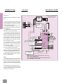
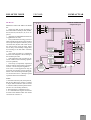
1
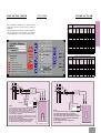
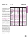
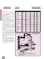
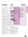
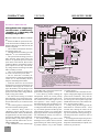
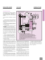
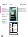
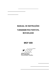
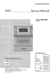
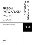
Bulletin
209EE
VEC204D MULTIFUNCTION REGULATOR
COMPACT STATIC EXCITER / DRIVER
VEC204D Static Exciters
BULLETIN 209EE
VEC204D/1/F/50
The VEC 200 series is a product family that
includes AVRs (Automatic Voltage Regulators) for Generators, Static Exciter and Drivers for Synchronous Motors and Alternators, High Current Controlled Rectifiers or
Simple 1 quadrant DC Motor Drives. The
VEC204D is a multifunction Regulator / Exciter / Driver well suited to Synchronous
Motors applications.
The VEC204D is an economical multifunction, monoboard architecture, plug in, reliable product with good performance.
The VEC204D incorporate some functions
and protections features. The type of control signal can be chosen when ordering.
The VEC204D has separate P + I + D adjustments that together with its sensing
characteristics enable it to fit in virtually
any process. Five adjustments are available at the front panel.
Eight LED indicates its functions and failure conditions.
Eight DIP Switches at front panel, simplify
the selection of functions.
The removable connector allows the control module to be cahnged easily.
The VEC204DC control module is the core
of the system. Wen plugged into a power
module, from 10 to 2000 Amperes, air cooled
or to 50000 Ampere water cooled, a final
compact exciter can be formed or if mounted inside a panel, with auxiliary equipment
(such as Circuit Breaker, Crowbar, Fuses
and Transformers), a complete Generator
or Synchronous Motor Exciter, Rectifier or
DC Motor Drive can be created.
The VEC204D is a good choice for reliable
and economical equipment, with good per-
VEC204D + EXCITATION TRANSFORMER
formance. The monoboard architecture,
encapsulated Plug In module allows a high
tolerance to hostile environments and to
vibrations besides allowing easy maintenance with a simple module change. The
power semiconductors used in equipment
to 1250 Amperes are encapsulated insulated base types, wich are highly reliable and
allow for simple and clean assembly.
The control module can be used with a controlled thyristor bridge, phase angle controlled or a diode bridge with Step Down
Chopper with IGBT (lower dead time operation).
There are two modes of Droop compensation available for Power Factor regulation
or for paralleling generators: by an external
power factor transducer or by an internal
power factor transducer included in the
module. The P.F. sensed by the Power Factor transducer is added to the sensing signal for the “Droop by Reactive Power Factor Compensation” method.
The Firing modules are fully encapsulated
in high insulation epoxy resins (20000 V/
mm) with optical isolation.
The diodes, thyristor or IGBT modules are
isolated base types with high reliability, simple an clean assembly and ease of maintenance.
COMPACTVAR
The VEC204D (series VEC 20X) is a
good choice for a synchronous motors
exciter. It can also be used as an AVR /
Exciter for generators, rectifiers or
simple speed regulation for DC motors.
The product has been made mainly to
achieve high reliability and simplicity.
It has applications for machines of up to
30.000 KVA or rectifiers to 50.000
Amperes.
The plug in monoboard encapsulated architecture, allowsfor simple, clean and
reliable assembly.
The digital function selection allows
easy commissioning and use.
The LED indicators and DIP switches
make the equipment friendly and intuitive.
Five options of input signals are available.
A complete line of Exciter, including
digital types is available.
• Application: Driver and Static Exciter for Synchronous Motors and Generators, AVRs, Rectifier, DC motors
Drive.
• Available control signal:
0 to 5 V, 0 to 10 V, Potentiometer, 0 to
20 mA, 4 to 20 mA.
• Modes: Main variable regulation with
Droop by secondary variable (Compound), allowing power factor regulation for synchronous motors and reactive droop compensation for parallel
operated generators or speed regulation
for DC motors.
Trips: Oversensing (main variable),
Oversensing (secondary variable), Overtemperature, Loss of signal and Surge
Overcurrent on IGBT (optional).
• Indicators: Power On, Enable, Droop,
Signal Loss, Oversensing main, Oversensing secondary, Overtemperature,
and Surge Overcurrent on IGBT.
Function Selections: 8 Digital Switches
(DIP Switchs).
Bridges: 3Phases or 2Phases, fully controlled Tyristor Bridge or 3Phase Diode
Bridge plus Step Down Chopper.
I3
COMPACTVAR
VEC204D
SYNCHRONOUS MOTORS:
•
RECTIFIERS:
FIELD CURRENT REGULATOR OR POWFACTOR REGULATOR FOR BRUSHLESS
SYNCHRONOUS M OTORS OR A UXILIARY
ROTARY EXCITER TO 50 AMPERES FIELD CURRENT, OR STATIC EXCITERS FOR COLLECTOR
RING TYPE SYNCHRONOUS MOTORS TO 2000
AMPERES FIELD CURRENT:
(the possibility of a nom application of the
resistor is virtually none).
The power module is connected to an exciter transformer that provides insolation
and an appropriate voltage to get the correct field ceilling voltage (Compliance).
This mode allows regulations of the excitation current and/or the polar angle (power factor) at the set point. The regulation
can be done by closed loop constant current or with droop by Polar Angle (Power
Factor) or by pure closed loop power factor regulation. The possibility of maintaining both loops closed, with an adjusted
percentage of compounding allows for
stable operation. It is difficult to achieve
stability in regulators with only P.F. regulation mode. The Power Factor is digitally
measured, by means of signals from a P.T.
and a C.T. in the stator circuit or by an
external transducer like the GE Multilin
SPM.
The regulation can be selected for “Constant Field Current”, “Field current regulation with Reactive Droop Compensation” (or “Constant Power Factor if Droop
is settled to 100%”).
The protection functions “Loss of Signal”,
“Field Overcurrent” and “Exciter Overtemperature” are active in this mode.
Some parameters can be adjusted on the
front panel: Proportional gain (P - a pure
proportional action), Integration time (I a integration time action), Derivative time
(D - a pure derivative action), Current or
Power Factor scale and Droop percentage of Droop from 0 to 100%.
In this application, with a Collector Ring
motor or Brushless Motor with Varixx M1
type “Control Box” inside, the field is applied near the end of the starting period.
For a brushless motor with Varixx “Control Box” type M2 inside, the field can be
applied at the beginning of the starting
period.
The discharge resistor (shunt resistor)
must be applied during the whole starting
time (in Collector Ring type motors) by a
contactor or by a special Crowbar from
Varixx. The Crowbar is much more reliable
AVR (AUTOMATIC VOLTAGE REGULAVOLTAGE REGULATOR FOR BRUSHLESS
GENERATORS OR GENERATORS WITH EXTERNAL AUXILIARY ROTATING EXCITER TO 50
AMPERES FIELD CURRENT OR STATIC EXCITER
ER
I4
BULLETIN 209EE
GENERATORS:
•
TOR):
FOR COLLECTOR RING TYPE GENERATORS TO
2000 AMPERES FIELD CURRENT:
This mode allows a constant voltage to be
kept at the generator output and it allows
for reactive current compensation in parallel operated generators for KVAR sharing
with other machines or with the electrical
supplier network. The reactive load sharing is achieved by the “Droop” method
based in the measured machine’s Power
Factor.
The power factor is digitally measured, by
means of signals from a P.T. and a C.T. in
the stator circuits or by an external transducer, like the GE Multilin SPM model. In
both cases the Droop rate can be adjusted
from 0 to 10%.
The regulation can be selected by an external command, for “Constant Voltage” or
“Compound Voltage with Reactive Droop
Compensation”.
The protection functions “Loss of Signal”,
“Generator Overvoltage” and “Exciter Overtemperature” are active in this application.
Some parameters can be adjusted on the
front panel: Proportional gain (P - pure proportional action), Integration time (I - a integration time action), Derivative time (D pure derivative action), Voltage scale or
Power Factor scale and Droop percentage
from 0 to 10%.
Automatic Build Up with manual enabling
is available in this mode.
• VOLTAGE OR CURRENT REGULATOR FOR
AIR-COOLED RECTIFIERS TO 2000 AMPERES
OR WATER-COOLED RECTIFIERS TO 50000
AMPERES FOR ELECTROLYSES (FOR HYDROGEN
PRODUCTION), CHEMICAL CELLS, ALUMINUM
REDUCTION, GALVANIC METAL DEPOSITION ,
INDUSTRIAL RECTIFIERS AND OTHERS:
Thes mode allows the output voltage or
current to be kept stable even in the presence of variations of the load or line.
The mode can be selected to constant current, constant voltage or compounded.
The protection functions “Loss of Signal”,
“Overcurrent” or “Overvoltage” and “Exciter Overtemperature” are active in this
mode.
Some parameters can be adjusted on the
front panel: Proportional gain (P - a pure
proportional action), Integration time (I - a
integration time action), Derivative time (D
- a pure derivative action), Voltage scale or
Current scale and Droop percentage.
Additionaly, rising and falling ramps can
be generated by external accessories such
as a programmable digital potentiometer
from Varixx.
The complete rectifier in a metallic panel
can be combined with PLC for control and
fault memorization, circuit breakers, fuses,
cooling systems with valves, heat exchangers, pumps and other protection relays such
as flux relay, pressure relay and so on. Varixx
is able to construct rectifiers to 150.000
Amperes.
CC MOTORS:
SIMPLE AC/DC DRIVE, FOR ONE QUADRANT
DC MOTOR SPEED CONTROL. APPLIED IN PROCESS THAT DOES NOT NEED BRAKING OR INVERSION OF ROTATION DIRECTION.
This regulator is optimized for use in Synchronous motors excitation, so in this mode
of use a restricted set of of resources are
usesd to keep the motor current/speed at a
constant set point.
The speed is sensed by a feedback signal
provided by a tachogenerator or DC transducer.
BULLETIN 209EE
COMPACTVAR
VEC204D
The regulation mode is by speed closed
loop plus current closed loop to achieve
stability.
The protection functions “Loss of Signal”,
“Overcurrent” or “Overspeed” and “Drive
Overtemperature” are active in this mode.
STATIC EXCITER TYPE PHASE ANGLE
WITH THYRISTOR BRIDGE
Models Nominal Maxim.
VEC204D Current Current
( A ) ( 1min )
(A)
25
75
0025
50
150
0050
100
300
0100
150
450
0150
200
600
0200
250
750
0250
300
900
0300
400
1200
0400
500
1500
0500
650
1950
0650
750
2250
0750
1000
2800
1000
1250
3250
1250
1500
3750
1500
1750
4375
1750
2000
5000
2000
Surge Fan Wide
Current Forc./ (W )
(10 mS) Natural mm
(A)
350
N
225
700
N
240
1900
F
290
3600
F
340
5200
F
377
5200
F
377
6600
F
377
8000
F
377
8000
F
377
12500
F
377
14500
F
377
14500
F
540
15000
F
540
19000
F
540
19000
F
800
30000
F
800
High Long.
(H) (L)
mm mm
290
290
290
290
290
330
380
430
480
530
580
850
850
950
800
900
200
270
270
270
270
270
300
300
300
330
330
315
315
315
390
390
PWM TYPE STATIC EXCITER
WITH IGBT STEP DOWN CHOPPER
Models Nominal Maxim. Surge Coolin. Wide. High
VEC204D Current Current Current Forc./ ( W ) ( H )
( A ) (1min) (10 mS) Natural mm mm
(A)
(A)
25
50
100
N
225 300
0025
50
100
200
N
240 290
0050
100
200
400
F
290 290
0100
150
300
600
F
340 290
0150
200
400
800
F
377 280
0200
250
500
1000
F
377 330
0250
300
600
1200
F
377 380
0300
400
800
1600
F
377 430
0400
500
1000 2000
F
377 480
0500
R
S
T
Long
(L)
mm
200
270
270
270
270
300
300
300
300
R S T
3-PHASES
Y/Y OR D/D
E XCITATION
TRANSFORM.
CB1
1-PHASE
EXCITATION
TRANSFORM.
CB1
CB2
CB2
FUSES
R´
S´
T´
T RANSFORM. N´
Notes:
1: The synchronism signal is taken internally
from the power input R, S and T, however in
cases the wave of the exciter transformer is
very distorted or with noises (rarely), it can be
necessary to use a synchronism transformer
in separate, as shown.
2: In this case the Exciter Transformer cannot
present phase rotation, therefore they should
be type Y/Y or D/D types.
3: The synchronism transformer should be
Y/Y type and it`s primary reels should be
connected to the primary of the exciter
transformer.
R
S
B1
B2
B3
FUSES
T
OPTIONAL
R S
B1
1-PHASE
115 V B2
SYNC .
TRANSFORM. 5 VA B3
B4
B4
VEC204DC
OPTIONAL
3-PHASES
Y/Y
S YNC.
Notes:
1: The synchronism signal is taken internally
from the power inputs (R, S) however in
cases the wave of the exciter transformer is
very distorted or with noises (rarely), it can be
necessary to use a synchronism transformer
in separate, as shown.
2: The polarity of the transformers is
not important.
VE C 2 04 D C
115V
5VA
I5
COMPACTVAR
VEC204D
BULLETIN 209EE
DIP SWITCH SELECTIONS:
LED INDICATORS:
FRONTAL ADJUSTMENTS:
• S1- “Setting Range 10%/100%”:
Selects setting range: narrow or wide.
• S2- “Droop Internal/External”: Selects the power factor transducer source
for the “Droop” signal.
• S3- “Droop Polarity”: Selects the
polarity actuation of the Droop signal (internal or external).
• S4- “Regulator / Drive”: When
“OFF” the “Normal” mode is selected,
with regulation based on the error signal.
When “ON” the “Drive” mode is selected
and the output is proportional only to sthe
set point signal (reference). In this case
there is not a closed loop and the equipment is simply a Drive for external regulators or manual adjustment.
• S5- “Proportional Gain”: Enables
the pure proportional gain error amplifier. The value is adjusted on the front panel for the best response, without oscillations and with minimum overshoot and
undershoot. It is used in almost all applications.
• S6- “Integrative Time”: Enables
the I portion of the error amplifier. The
integrative time is adjusted in the front
panel for the best stability, to get the minimum overshoot, undershoot and the fastest reaction time possible. Usually it is
used in almost all applications.
• S7- “Derivative Time”: Enables the
pure derivative gain error amplifier. The
value is adjusted on the front panel for
the fastest reaction time, but without oscillations and to get the minimum overshoot, and undershoot possible. It is used
in very few applications.
• S8- “Droop Scale 10% / 100%”:
When “OFF” the 10% scale is selected
for use with generator Droop (for reactive
load sharing). When “ON” (100%) the
100% scale is selected for use with synchronous motors (for constant power factor regulation) or DC motors (for speed
regulation).
• L1- “Power ON”: (Green) - Indicates
that the equipment is powered ON.
• L2- “Enable”: (Yellow) - Indicates
that the equipment is enabled by a signal at
the corresponding connector.
• L3- “Droop”: (Yellow) - Indicates that
there is a Droop command at the corresponding connector.
• L4- “Signal Loss”: (Red) - Indicates
“Loss of Signal” (set poit signal loss). This
function is enabled by the enable signal at
the corresponding connector. The condition is maintained (memorized) until a “Reset” signal or power down occurs or the
“Enable” is inhibited.
• L5- “Overtemperature”: (Red) - Indicates an overtemperature condition at the
power devices heater exchange.
• L6- “Main Oversensing Trip” (Red): Indicates a trip by excess in the primary variable at connector 6. The trip condition is maintained (memorized) until a Reset signal or power down occurs or the “Enable” is inhibited.
• L7- “Secondary Oversensing Trip” (Red): Signalizes a trip by excess in the secondary variable at connector 5. The trip
condition is memorized until a Reset signal, inhibition or power down occurs.
• L8- “Surge overcurrent on IGBT” (Red) - Only utilized on the PWM Step
Down Chopper Type. Indicates (do not inhibits output) a surge overcurrent on the
IGBT. It is auto resetable on pulse by pulse
base.
• P1- “Proportional Gain”: adjustable
from 0 to 100% of the factory predefined
value. Active if selected at the corresponding DIP switch. As this is a pure proportional amplifier, the adjustment mainly influences the dynamic regulation. It must be
adjusted to get the fastest compensation
for input changes but without instability.
• P2- “Integration Time”: This is a integrative gain amplifier adjustable from 0 to
100% of the factory predefined value. Active if selected at the corresponding DIP
switch. It must be adjusted to get the best
stability possible with minimum overshoot
and undershoot. This portion of error amplifier is mainly responsible for the static
regulation and it must be selected in almost
all cases.
• P3- “Differentiation Time”: adjustable from 0 to 100% of the factory predefined value. Active if selected at the corresponding DIP switch. It allows a fast compensation of dynamic variations. Normally
utilized for generators with slow response
time. It must be adjusted to get the fastest
response and the best stability. This portion of error amplifier is mainly responsible
for dynamic regulation.
• P4- “Scale”: “End of Scale” calibration if a 100% scale is selected at DIP switch
S1, or calibration of the nominal value for
mid- scale (if 10% selected at DIP S1).
• P5- “Droop”: Adjustable from 0 to
+10% Droop if DIP switch S8 is ‘OFF”. A
10% compounding rate results with 90º lagging or leading polar angle of synchronous
motors and generators rotors. If DIP switch
S8 is “ON” the adjustment is from 0 to 100%
from the feedback signal for the synchronous motor power factor or the DC motor
speed. Normally used from 0 to 5% for parallel operating generators and from 50% to
80% for synchronous motors to get constant power factor operation, maintaining
the current closed loop, for stability. For
DC motors with tachometer feedback it is
usually set from 50% to 80% due to the
same reason.
• P6- “Minimun Current”: Used mainly in synchronous motors application, it
avoids that the excitation current can drops
bellow the preset value, avoiding that the
motor de-synchronize.
I6
Note: All protection functions from L4 to
L7 have a 0.25 second time delay to avoid
erroneous tripping.
BULLETIN 209EE
CONTROL MODULE ELECTRICAL DATA:
The side table shows the electrical data of
the inputs and outputs of the control module, for both connectors (the front connector and the rear side DB15 connector).
Also the signals connected to the power
module are shown.
The chosen order of some signals allows
the various options to be shown separately. Each piece of equipment comes with a
customdata sheet filled in with the actual
data type and values. The custom data
sheet also shows other important information including signals, date of delivery,
guarantee period, input and output data etc.
The user’s manual includes this bulletin,
electrical drawings, mechanical drawings,
Start Up instructions and the custom data
sheet.
Special Adjustment for Synchronous Motors Application.
The control module has in its posterior part,
an adjustable potentiometer (trimpot),
placed exactly in this part by precaution.
This trimpot is to adjust the minimum current
that the exciter can supply to load and it is
very important for application in
synchronous motors with operation in
“Constant Power Factor” mode. In this
application, case the motor has a very
variable or pulsed load, in the moment of a
sudden retreat of the load, the exciter, in
the attempt of compensating the power
factor, would totally remove the excitation
for some instants, what would take the
motor to lose the synchronism (Step Out).
This way the exciter, in this application
mode, should be adjusted to supply at least
a minimum current that doesn't take the motor to de-synchronize with no load or light
load. This trimpot is only adjusted once,
during the start up. To adjust it, disconnects
the control module of the power module
and adjust it at 30% of the scale for example.
Test the equipment with motor stopped and
with the current set point adjusted to
minimum. Readjust the trimpot until get the
requested current.
COMPACTVAR
VEC204D
CONNECTOR
Top Connector
Set Point Opt 1 (V/Pot)
Set Point Opt. 2 (V/Pot)
Set Point Opt. 3/4 ( I )
Droop Signal Opt. 1
Droop Signal Opt. 2
Droop Signal Opt. 3/4
CT Fase S (P. F. Sensing)
4/3
4/3
4/3
5/3
5/3
5/3
7/3
Sense Input Opt. 1
Sense Input Opt. 1
Sense Input Opt. 2
Sense Input Opt. 2
Sense Input Opt. 3/4
Enable Input
Droop Input
Reset Input
6/3
6/3
6/3
6/3
6/3
8/3
9/4
10 / 3
Signal Type
Input Voltage
Input Voltage
Input Current
Input Voltage
Input Voltage
Impedance
Input Current
11 / 12
11 / 12
11 / 12
11 / 12
Voltage
Voltage
Current
Current
Power Supply Input
Power Supply Input
1/2
1/2
Voltage
Power
DB25 Connector
Firing Signal/Commom DB10 toDB15 / DB9 Output Volt
DB10 toDB15 / DB9 Output Current
Firing Signal
DB3
Source V / I
+ V Output (p/IGBT)
DB4
V / Impedance
IGBT O. C. Input (Fail)
Power Module
Sensing Phase RT
Build Up Enable
Opt. Synch Signal
Fan Power Supply
DB2 - DB5
DB1 - DB5
DB 6/7/8 - DB5
DB 6/7/8 - DB5
B9 / B10
B7 / B8
B1 / B2 / B3 / B4
B5 / B6
Units
----
1000
V DC/10 K Ohm
VDC/10 K Ohm
mA (250 Ohms)
VDC (10 KOhm)
VDC(10 K Ohm)
Ohms
mA (250 Ohms)
10
10
10
—
—
—
—
0-4/250
—
—
—
Volts
Ohms
Volts
Ohms
mA/Ohms
mA DC
mA DC
mA DC
—
—
—
—
240
30
1
0,25
VAC
VCC
A AC
A CC
0
0
0/4
0
0
15
Input Voltage
—
—
Input Impedance
Input Voltage
—
Input Impedance
—
Input Cur./Imped. 0-4/250
Current Source
—
Current Source
—
Current Source
—
Fail Relay Contact
Fail Relay Contact
Fail Relay Contact
Fail Relay Contact
Over Temp. SPST
Sensing Phase RT
Synch / Common
Synch / Common
Minim. Nominal Maxim.
—
—
—
—
5
10 K
10
10 K
92 / 176 115 / 220 138 / 264
—
6
—
10
—
—
—
V/I
—
V / Impedance 10 / 10K
Input Voltage
10
Input Impedance
—
Voltage / Power
Voltage / Curr.
Voltage
Voltage
--250
100
5
10
20
5
10
11
12
—
20
—
12 / 50
12 / 10 K
—
10 / 5
__
20
15K
V AC
Watts
Volts DC
mA DC
VCC / mA CC
V / K ohm
—
V DC / mA CC
50 / 10K V DC / Ohms
28
V AC
—
Ohms
60 / 3
115 / 3 150 / 3
Volts / VA
12 / 30
VCC / mADC
60
115
150
V AC / 3 Watts
92 / 176 110 / 220 138 / 264
V AC
see Tag
I7
COMPACTVAR
FUNCTIONS FOR EACH APPLICATION TYPE:
The side table shows the functions available to each application, with the type of
action (selection or adjustment) and the
range of adjustment.
When a trip occurs, the output will be inhibited, the LED will be lit and the trip
relay will be energized.
There is a time delay of 0.5 seconds for
the effective actuation of the protection.
The error amplifier is a selectable P + I +
D type. This way it can be adapted to virtually any application because of its versatility. The user can select and adjust the
response types needed.
The second portion, the “I” error amplifier, is mainly responsible for the static regulation. Its Integration time is adjustable
from 0 to 100%. This portion of error amplifier needs to be selected in almost all
applications.
The first portion of the error amplifier is a
pure proportional gain amplifier and it is
mainly responsible for dynamic regulations. It is usually used in almost all applications, to improve the system response
time and obtain fast corrections. It must
be adjusted to avoid instability and yet
get fast response time with low overshoot
and undershoot.
The third portion of the error amplifier is
a pure derivative gain amplifier and it is
mainly responsible for dynamic regulations. It is necessary in a very few applications, to increase the stability and obtain fast corrections. It must be adjusted
as low as possible for stability and better
response time.
VEC204D
BULLETIN 209EE
FUNCTIONS
SYNC MOTOR
GENERATOR
RECTIFIER DC MOTOR
Type / Default
Type / Default
Type / Defautl Type / Default Opt./Selec./Adj
Option
Option
Option
Option
Opt.
0 TO 10 VOLTS SET
Option
Option
Option
Option
Opt.
0 TO 5 VOLTS SET
Option
Option
Option
Option
Opt.
0 OR 4 TO 20 MA SET
Option
Option
Option
Option
Opt.
P OTENTIOMETERSET
S1
10% / 100% SET (SEL. / ADJ.)
0 - 10% / 0 - 100%
0 - 100%
0 - 100%
0 - 10%
Adj. 1 - 50
Adj. 1 - 50
Adj. 1 - 50
Adj. 1 - 50
P1 / S5 ON
P ROPORTIONALGAIN
Sel./ 0 / 0.01-1S
INTEGRATIVE TIME
Sel./ 0 / 0.01-1S
Sel./0/0.01-1S Sel./0/0.01-1S P2 / S6 ON
Sel./ 0 / 0.01-1S
Sel./ 0 / 0.01-1S
Sel./0/0.01-1S Sel./0/0.01-1S P3 / S7 ON
DERIVATIVE TIME
N.U.
Option
Option
N.U.
Opt.
VOLTAGE REGULATION
Option
N.U.
Option
Option
Opt.
CURRENT REGULATION
N.U.
N.U.
P5 / S8
REACIVE DROOP COMPENSATIONSel./Adj. 0 to 100% Sel./Adj.0 to 10%
N.U.
N.U.
P5 / S8
P OWER F ACTOR REGULATION Sel./Adj. 0 to 100% Sel./ Adj. 0 to100%
Compound w/ Curr.
(INTERNAL / EXTERNAL)
Compound w/ Volt.
+/- 10%
+/- 10%
Select
Select
DROOP INTERNAL / EXTERNAL
Select
Select
DROOP P OLARITY
Select
Select
REGULATOR / DRIVE OPERATION
Select /Adjust
Select /Adjust
DROOP RANGE
0 - 10% / 0 - 100% 0 - 10% / 0 - 100%
OK
OK
SIGNAL LOSS
Select / 120%
Select / 120%
OVER SENSING TRIP
90º C
90 C
OVER TEMPERATURE TRIP
Option.
Option.
SURGE IGBT OVER CURRENT
OK
OK
P OWER ON INDICATION
OK
OK
ENABLE INDICATION
OK
OK
DROOP INDICATION
OK
OK
F AIL INDICATION
OK
OK
TRIP INDICATION
+/- 10%
Select
Select
Select
Select /Adjust
10% / 100%
OK
Select / 120%
90º C
Option.
OK
OK
OK
OK
OK
SCALE ADJUST
S
FUSES
T
CB2
R S
or
3-PHASES
E XCITATION
TRANSFORM.
FUSES
CB1
R
S
T
B1
B2
B3
12
11
B4
B5
B6
FAN P.
SUPPLY
T RANSFORM. 115 V
30VA
115 V
POWER
3
VEC204DC
B9
B10
(+)
(-)
FAIL
POT 500R
C TE CURR.
DROOP
5
3
SENSING PHASE RT - FOR CTE. P.F. OP .
COM
N.O.
4
1
2
7
3
C.T. IN/1A - PHASE S - FOR CTE P.F. OPERATION
AMPLIF.
SHUNT
VSA650
VARIX
C TE P.F..
3
8
9
6
3
10
ENABLE
DROOP
RESET
VEC204D
SYNCH
MOTOR
SLIP R ING
OR B RUSHLESS
(+)
(-)
C ROWBAR VARIX
SHUNT
D ISCHARGE
R ESISTOR
Notes:
1: All Wires to connector 3 (Common) must be connected straight to it.
2: For 2-Phases Excitation Transformer / P.M.G. or CC P.M.G. it is necessary
the use off the PWM model.
3: For 3-Phases Excitation Transformer / P.M.G. both types could be used
(PWM or Phase Angle).
I8
P4
S2
S3
S4
P5 / S8
L4
S2 / L4
L5
L8
L1
L2
L3
L4/L5/L6/L7
L8
TYPICAL APPLICATION
Simplified diagram
2-PHASES
EXCITATION
TRANSFORM.
R
+/- 10%
Select
Select
Select
Select /Adjust
10% / 100%
OK
Select / 120%
90º C
Option.
OK
OK
OK
OK
OK
BULLETIN 209EE
COMPACTVAR
VEC204D
CONTROL MODULE VEC204DC
VEC204DC
The side drawing shows the connections
to the top connector and rear connector
(DB15) of the VEC204DC.
The connectors 1 and 2 are plugged to the
command power supply of 110 or 220 VAC
depending on the model.
Connector 3 is the common connector for
all the inputs.
Connector 4 is the set point input. This input can be chosen when ordering (0 to 5
VDC or 0 to 10 VDC or 500 ohms digital
scale potentiometer, 0 to 20 mA or 4 to 20
mA).
Connector 6 is the input for the primary
variable or main variable (equal signal options). This signal can be provided by an
insolated shunt amplifier, a hall sensor, a
voltage transducer, etc.
Connector 5 is the secondary input signal
or Droop signal (equal signal options). This
signal can be provided by a Power Factor
Transducer (Ex: GE-Multilin SPM model),
Hall Effect sensor, tachogenerator, etc.
Connector 7 is the input for an optional
current transformer for power factor sensing (Polar Angle sensing) for synchronous
motors and generators (for internal power
factor transducer). The voltage phase is
measured at connector B9 and B10 of the
power module and routed to connector DB1
and DB5 of control module; in this way the
C.T. must be on the cable corresponding to
connector B2 (the middle cable). The DIP
switch S2 selects one of the transducer, external or internal.
The connector 8 is the input for a dry contact for the “Enable” command.
Connector 9 is the input for a dry contact
for the “Droop” command.
Connector 10 is the input for a dry contact
for the “Reset” command. When a trip occurs, the condition is maintained until a
Reset signal or power down occurs, or the
enable is inhibited.
Connectors 11 and 12 are the N.O. Dry contacts of the fail indication relay.
DB1 is the input for sensing RT phase for
the internal Power Factor Transducer (common at DB5).
DB2 is the input for a N.C. dry contact of a
1 110 / 220 VAC
2 110 / 220 VAC
3 Common
500R
4 Set Point
DB 1
SENSING P HASE RT
DB 2
BIMETALIC TEMPERATURE (N.C.)
DB 3
(+) FIRING IGBT MODULE
DB 4
FAULT IGBT
DB 5
"COMMON" SENSING/SINCRO
Transducer
5 SECONDARY SENSING DB 6
SYNCH R
Transducer
6 PRIMARY S ENSING
DB 7
SYNCH S
7 P. F. SENSING
OPTIONAL
DB 8
SYNCH T
DB 9
"COMMON" FIRING MODULES
DB10
FIRING MODULE 1R
DB11
FIRING MODULE 2R
0 to 10 VCC
DB12
FIRING MODULE 1S
0 to 20 mA
DB13
FIRING MODULE 2S
4 to 20 mA
DB14
FIRING MODULE 1T
DB15
FIRING MODULE 2T
C.T. PHAS. S
OPTIONAL
S IGNALS
B4/ B5/B6
0 to 5 VCC
ENABLE
DROOP
RESET
FAIL
N.O.
COM.
8 Enable
9 Droop
10 RESET
11
12
temperature sensor.
Connectors DB3 and DB4 are used for connection of an optional IGBT firing module
(only in models with PWM chopper control). DB3 is the +V supply and DB4 is the
input for an overcurrent trip signal from the
IGBT firing module.
Connectors DB5 to DB8 are the inputs for
synchronizing signal. Connectors DB9 to
DB15 are the outputs for the thyristors firing modules (DB10 to DB15) or the IGBT
(DB10 and DB11).
The Control Module and the firing modules
are fully encapsulated with high insolation epoxy resins. (20000 V/mm).
I9
SYNCHRONOUS MOTOR EXCITER:
Thisapplication isforalltypesofsynchronous m otors: “Collector Ring”,
“Brushless” or “Collector Ring with
AuxiliaryRotaryExciter”.
IMPORTANT POINTS FOR WIRING AND START
UP :
• Selects the DIP for synchronous motor as shown at table. Normally S1 ON, S4
OFF, S5 OFF, S6 ON, S7 OFF, S8 ON, S2
and S3 as required.
• The excitation transformer must have
an adequate power rate.
• The fuses must be ultra-fast types with
adequate i2T (see custom data sheet).
• The synchronism for firing tyristors is
taken internaly from power inputs, but
there are an optional input for external
synch at the connectors B1, B2, B3 with
common at B4, for cases that the signal at
power imputs are too dirty. The secondary voltage must be according to the data
table. Normally not used.
• The C.T. for power factor sensing must
be on the correct motor power cable.
• The C.T. must have a secondary rating of maximum 1 Amperes and minimum
15 mA. A C.T. with secondary rate of 5
Amperes will damage the module.
• If the user chooses to use an external
transducer for power factor measuring, the
transducer must supply the correct voltage to the module, corresponding to total
scale from totally inductive to totally capacitive. The center scale voltage must be
equal to unity power factor.
• For field current sensing an isolated
shunt amplifier can be used with an output corresponding to the scale of the module (VSA605A Varix). It can also be a hall
sensor.
• The control signals are commented on
the control module drawing sheet.
• For “Collector Ring” motors or
“Brushless” motors with M1 type Control Box inside (GE -Varixx), the field must
be applied at 95% to 99% of the synchronous speed, preferably with a “Field Application Relay” with polar angle sensing such as the VR 9045A Varix or GE Multilin SPM model.
• For “Brushless” motors with M2 type
I 10
VEC204D
BULLETIN 209EE
TYPICAL APPLICATION
Simplified diagram
R
S
2-PHASES
EXCITATION
TRANSFORM.
or
FUSES
T
CB2
R S
or
3 PHASES
PMG
2 PHASES
PMG
3-PHASES
EXCITATION
TRANSFORM.
R S T
R S
FUSES
CB1
R
S
FAN P.
SUPPLY
TRANSFORM. 115 V
30VA
115 V
(+)
(-)
SENSING PHASE RT
AMPLIF.
SHUNT
VSA650
VARIX
3
5
3
B10
R S
FAIL
POT 500R
CTE C URR.
DROOP
B9
(+)
(-)
COM
N.O.
4
REFER. OPT.
1
2
7
3
T.C. IN/1A - PHASE S
P.F. TRANSDUCER
OPCIONAL
12
11
B4
B5
B6
-
T
B1
B2
B3
POWER
CC
PMG
+
REFER. OPT.
4
+ 4 TO 20 M A -
REFER. OPT.
4
+ 0 TO 5V -
VEC204DC
COMPACTVAR
CTE P.F..
or
3
8
9
6
3
10
ENABLE
DROOP
RESET
VEC204D
SYNCH
MOTOR
SLIP RING
OR BRUSHLESS
(+)
(-)
CROWBAR VARIX
C1 OPTION .
SHUNT
C1 OPTION .
DISCHARGE
RESISTOR
Notes:
1: The Circuit Breaker CB2 and its connection
is not used in case off P.M.G. - Permanent Magnet Generator.
2: IF used with P.M.G. with 2 Phases connect input T together input R
3: Connect Power Input (1 and 2) to P.M.G. if it’s voltage range is adequate.
4: The CT and PT at connectors 7/3 and B9/B10 substitutes the Power
Factor Transducer at connectors 5/3 for Droop purpose.
5: All Wires to connector 3 (Common) must be connected straight to it.
6: For 2-Phases Excitation Transformer / P.M.G. or CC P.M.G. it is necessary
the use off the PWM model.
7: For 3-Phases Excitation Transformer / P.M.G. both types could be used
(PWM or Phase Angle).
Control Box (GE - Varixx) the field can be
applied when starting begins.
• At the Start Up, before enabling the
Droop/Power Factor, the correct polarity
of the signal should be verified. The excitation current can be raised to get a P.F. of
0.85 capacitive. If the voltage is greater
than that with unity P.F., the polarity is correct. If not, change the polarity of the C.T.
or change the DIP switch S3 (Droop polarity). In normal operation the Droop command must be closed 2 to 5 seconds after
applying the field or with the load application command (FCX relay) to avoid overshooting or instability.
• For “Collector Ring” type motors a field
discharge resistor (shunt resistor) must be
applied during the whole starting period,
by a field contactor or by a more reliable
“Crowbar” (Varixx).
• B9 and B10 are the connectors for sensing the voltage phase angle (by the internal
power factor transducer). They must be
connected at the cables which are not used
for sensing the current phase angle (the
middle cable in this case). The nominal voltage is 115 VAC (60V to 150 V).
• Usually, during the starting period, the
mode must be “Constant current”. A few
seconds after starting the mode can be
changed to “Droop”. This way overshooting is avoided because during starting period the power factor of motor is near 0,2
inductive.
• For this application adjust the pot P6 to
obtain a minimum excitation current (for example 20% of teh nominal) as required, even
with the set point at zero.
BULLETIN 209EE
GENERATORS EXCITERS:
This application is for all types of alternators: “Collector Ring”, “Brushless” or
“Collector Ring with Auxiliary Rotary
Exciter”.
COMPACTVAR
VEC204D
TYPICAL APPLICATION
Simplified diagram
R
S
2-PHASES
EXCITATION
T RANSFORM.
T
or
FUSES
or
R S
2 PHASES
PMG
3 PHASES
PMG
3-PHASES
EXCITATION
TRANSFORM.
CB1
IMPORTANT POINTS FOR WIRING AND START
UP :
+
-
CB2
R S T
R S
FUSES
R
S
12
11
B4
BUILD UP E NABLE
POWER
115 V
TRANSFORM.
115 V
30 VA
1
2
7
3
6
3
(+)
(-)
B9
SENSING PHASE RT - OPTION.
C.T.
GENERATOR
(SLIP RING
OR B RUSHLESS)
POWER F ACTOR
TRANSDUCER
OPTION .
(+)
(-)
CROWBAR V ARIX
OPTIONAL
B10
REFER. OPT.
4
REFER. OPT.
4
8
9
5
10
3
Fan P.
Supply
B5
B6
COM. FAIL
N. O.
POT 500R
4
REFER. OPT.
B8
C.T. IN/100 MA - PHASE S - (OPTION).
VOLTAGE
TRANSDUCER
3
B7
R S
T
B1
B2
B3
VEC204DC
• Select the DIP as shown in the table on
page I8 for generators. Normally S1 OFF,
S4 OFF, S6 ON, S8 OFF, and S2, S3, S5, S7
as required.
• The excitation transformer must have
adequate power and voltage to get the correct ceilling voltage.
• The fuses must be ultra-fast types with
adequatei2T (see custom data sheet).
• The synchronism for firing tyristors is
taken internaly from power inputs, but there
are an optional input for external synch at
connectors B1, B2, B3 with comon at B4,
for cases that the signal at power inputs
are too dirty. The secondary vltage must
be according to the data table. Normally
not used.
• The C.T. for power factor sensing must
be on the correct motor power cable.
• The C.T. must have secondary rating of
maximum 1 Ampere and minimum 15 mA. A
C.T. with secondary rate of 5 Ampere will
damage the module.
• If the user chooses to use an external
transducer for power factor, the transducer must supply the correct voltage to the
module, corresponding to total scale, from
totally inductive to totally capacitive. The
center scale voltage must be equal to unity
power factor.
• For voltage sensing an insolated transducer cam be used with output corresponding to mid-scale of the module. It is preferable that at nominal voltage of the generator the transducer output is at mid-scale.
• The control signals are commented on
control module drawing sheet.
• The excitation must be applied only at
nominal speed.
• At the Start Up, before enabling definitively the Droop/Power Factor function,
the correct polarity of the signal should be
verified. The generator can be inductively
CC
PMG
+4
TO 20 MA -
+0
TO
or
5V-
ENABLE
DROOP
RESET
VEC204D
(+)
(-)
C1 OPTION .
C1 O PTION.
DISCHARGE
RESISTOR
Notes:
1: The Circuit Breaker CB2 and its connection
is not used in case off P.M.G. - Permanent Magnet Generator.
2: The Build Up Enable button is not used in case off use with P.M.G.
3: IF used with P.M.G. with 2 Phases connect input T together input R.
4: Connect Power Input (1 and 2) to P.M.G. if it’s voltage range is adequate
5: The CT and PT at connectors 7/3 and B9/B10 substitutes the Power.
Factor Transducer at connectors 5/3 for Droop purpose.
6: All Wires to connector 3 (Common) must be connected straight to it.
7: For 2-Phases excitation Transformer / P.M.G. or CC P.M.G. it is necessary
the use off the PWM model.
8: For 3-Phases Excitation Transformer / P.M.G. both types could be used
(PWM or Phase Angle).
loaded to get a P.F. close to 0.80 inductive.
Open and close the Droop command. With
Droop active the generator output voltage
should fall a little. If not, change the polarity of the CT or change the DIP switch S3
(Droop polarity). In normal operation the
Droop command must be closed for parallel operation and opened for single operation. This way you get better static regulation in single mode.
Refers to the specific bulletin for parallel
operated generators from Varixx.
• B9 and B10 are the connectors for
sensing the voltage phase angle (by the
internal power factor transducer). They
must be connected at the cables which is
not used for sensing the current phase angle (the middle cable in this case). The nom-
inal voltage is 115 VAC (60V to 150 V).
• Usually, in single mode operation (not
parallel) the mode must be “Constant voltage” (without Droop). This will improve
the static regulation.
I 11
COMPACTVAR
VEC204D
BULLETIN 209EE
RECTIFIERS:
IMPORTANT POINTS FOR WIRING AND START
UP :
TYPICAL APPLICATION
Simplified diagram
2-PHASES
RECTIFIER
TRANSFORMER
FUSES
Notes:
1- If used for external synch, the Inputs
B1, B2, B3 and B4 can be wired to a 3Phase or Open Delta transformer (B4 at
neutral or common of Star) without phase
rotation and 115 VAC secondary (model /
1).
2- The Diagram is a simplified version.
3- Is advisable that signal connections be
made with shielded cable with the shield
connected to connector 3.
I 12
S
T
R S
or
3-PHASES
RECTIFIER
TRANSFORMER
FUSES
R
S
T
B1
B2
B3
FAN POWER SUPPLY
POW. SUPPLY 115 V
TRANSF.
115 V
30 VA
DIGITAL POTENT . VPS510A VARIX FOR
R ISING AND LOWERING RAMPS (OPT.)
DEMAND
CONTROLER
OPTIONAL
SHUNT
AMPLIF.
VSA650
VARIX
12
11
B4
B5
B6
3
2
1
REFER. OPT.
4
REFER. OPT.
4
POT 500R
+
+ 4 TO 20 MA -
+
+ 0 TO 5V -
ENABLE
9
6
3
10
VEC204D
(+)
ELETROCHEMICAL
CELL, ELETROLITIC
CELL ETC.
FAIL
3
0 TO 5V
B3/B4
5
3
(+)
(-)
4
REFER. OPT.
COM.
N.O.
VEC204DC
• Select the DIP switch as shown in the
table on page I8 for rectifiers. Normally
S1 ON, S4 OFF, S5 OFF, S6 ON, S7 OFF,
and S2, S3, S8 as required.
• The main transformer must have adequate power and voltage to get the correct compliance.
• The fuses must be ultra-fast types with
adequate i2T (see custom sheet).
• The synchronism for firing thyristors
is taken internaly from power inputs, but
there are an optional input for external
synch at connectors B1, B2, B3 with
comon at B4, for cases that the signal at
power inputs are too dirty. The secondary voltage must be according to the data
table. Normally not used.
• For current sensing an insolated
Shunt amplifier can be used or a transducer with an output corresponding to
the scale of the module.
• The control signals are commented at
the control module drawing sheet.
• For rectifiers that need rising and falling ramps a digital programmable potentiometer can be used (VSP510A Varixx).
• An optional demand control could reduce the output power at hours with an
excess of demand power.
R
(-)
SHUNT
Notes:
1: For 2-Phases Rectifier Transformer it is necessary
the use off the PWM model.
2: For 3-Phases Rectifier Transformer both types could
be used (PWM or Phase Angle).
DEMAND
RESET
or
BULLETIN 209EE
COMPACTVAR
VEC204D
DC MOTORS
R
TYPICAL APPLICATION
Simplified diagram
T
F USES
R
S
T
B1
B2
B3
12
11
B4
3
FAN POWER SUPPLY
TACHO
INTERFACE
TACHO
AC/CC
SHUNT
A MPLIF.
VSA650
VARIX
1
2
4
+ 4 TO 20 MA -
REFER. OPT.
4
+ 0 TO 5V -
8
6
3
10
VEC204D
(+)
FIELD
POT 500R O R 0 TO 5 V
or
3
CC MOTOR
SERIES
(S AME FOR
COMPOUND AND
SEPAR. EXCIT .)
FAIL
REFER. OPT.
B5
B6
5
3
(+)
(-)
COM.
N.O.
4
REFER. OPT.
POWER S UP. 115 V
T RANSFORM.
115 V
30 VA
VEC204DC
IMPORTANT POINTS FOR WIRING AND START
UP.
• Selects the DIP switchs according to
the rectifier table. Normally S1 ON, S4 OFF,
S6 ON, S8 ON, and S2, S3, S5, S7 as required.
• All generic recommendations of the other applications are valid.
• The synchronism for firing tyristors is
taken internaly from power inputs, but there
are an optional input for external synch at
connectors B1, B2, B3 with comon at B4,
for cases that the signal at power inputs
are too dirty. The secondary voltage must
be according to the data table. Normally
not used.
• The signal provided by a tachometer
must have an adequate scale according to
the module input scale.
• This application only provides one direction rotation with no braking capabilities (one quadrant).
• The Droop (Compound) adjustment
must be between 50% to 80% to get simultaneous current and speed regulation.
Note: This is a side application only, for
processes not requiring precise speed regulation. There are more specialized regulators for this kind of use. (With pure speed
regulation and current limitation).
S
ENABLE
R ESET
(-)
SHUNT
Notes:
1- If used for external synch, the Inputs B1,
B2, B3 and B4 can be wired to a 3-Phase
or Open delta transformer (B4 at neutral
or common of Star) without phase rotation
and 115 VCA secondary (model /1).
2- The Diagram is a simplified version.
3- It is advisable that signal connections
be made with shielded cable with shield
connected to connector 3.
I 13
COMPACTVAR
BULLETIN 209EE
VEC204D
ACCESSORIES:
COMPLETE SOLUTIONS FROM VARIXX
• Ultra-fast fuses.
• Power transformers.
• Synchronism and sensing transformers.
• Shunt amplifier: VSA650A (60 mv/5V
isolated).
• Digital Potentiometer + servo controller: VSP510A.
• Multi-turn potentiometer panel with digital scale: VP1020E.
• “Field Application Relay”: VR9045.
• “Field Ground Fault Relay”: VR9030A.
• “Field Overvoltage Relay”: VR9031A.
• “Step-Out/Polar Angle Relay”:
VR9035A.
• “Field Loss Relay”: VR9034A.
• Other protection relays.
• Control Box (M1 or M2).
• Crowbar.
VARIXX or its integrators can offer complete systems, including panels, circuit
breakers, fuses, instruments, GE Multilin
Relays, PLC and much more. The equipment can be projected by our engineering
personnel to satisfy the needs of the customer.
Our field personnel can provide the Start
Up.
SPARE
PARTS:
• Control Module:
VEC204DC/X/X/X/X/X/X.
• Firing Modules: VDE115A
• VV1 and VV2: - Fans - see custom data
sheet at manual.
• VRN1 and VRN2: - Thermostats - see
custom data sheet at manual.
• VC12: - 12 way female connector.
• VS204/3E: - synchronism module.
• VBU200A/xxx: Build Up Module.
STATIC EXCITER WITH VEC 204D,
SYNCHRONOUS MOTOR
FOR
6000 HP
ORDER CODE
VEC204D/X/X/XXXX/XXX/X/X/X/X
A B
POWER
A SUPPLY
B
TYPE
C
D
E F G H
1 = 110 VAC
2 = 220 VAC
3 = OTHER
F3 = 3-PHASE ANGLE CONTROL
F2 = 2-PHASE ANGLE CONTROL
P3 = 3-PHASE BRIDGE / PWM
P2 = 2-PHASE BRIDGE / PWM
C CURRENT
NOMINAL CURRENT
VOLTAGE
NOMINAL VOLTAGE
D
OPERATION
E POINT
ADJUST
1 = 0 TO 5 VOLTS / POTENTIOMET.
2 = 0 TO 10 VOLTS / POTENTIOM.
3 = 4 TO 20 mA.
4 = 0 TO 20 mA.
POWER
1 = 0 TO 5 VOLTS / POTENTIOMET.
2 = 0 TO 10 VOLTS / POTENTIOM.
3 = 4 TO 20 mA.
4 = 0 TO 20 mA.
F FACTOR
SYGNAL
CURRENT
G INPUT
SYGNAL
H FAN
1 = 0 TO 60 mV.
2 = 0 TO 5 VOLTS
0 = W/O FAN
1 = 120 VAC
2 = 220 VAC
EXAMPLE:
VEC204D/1/F3/100/150/1/2/2/0: Synchronous Motor Exciter, 110 VAC Power Supply, 3-Phase Fire Angle Tyristor
Bridge, 100 Amper Nominal Current, 150 V Nominal Tension, 0 to 5 VCC / Potentiometer Settling, 0 to 10 VCC Power
Factor Signal, 0 to 5 VCC Current Signal Sensing, W/O Fan.
I 14
Varixx Industria Eletrônica
Rua Phelipe Zaidan Maluf 1501 - Distrito Industrial Unileste
Piracicaba - SP - CEP13.422.190 - Phone: (55) (19) 3424.4000 - Fax: (55) (19) 3424.4001
www.varix.com.br
e-mail: [email protected]
Varixx Electronics USA
10540
Fort
NW 50 Lauderdale
Second Court Florida
-
Plantation
33324
Toll Free: 1-800-238 6696 - Phone: (954) 572 5535 - Fax: (954) 572 0331
• STATICS EXCITERS FOR GENERATORS.
• STATICS EXCITERS FOR SYNCHRONOUS MOTORS.
• AVRS - AUTOMATIC VOLTAGE REGULATORS.
• SOFT STARTERS FOR MOTORS.
• POWER CONTROLLERS.
• SSCS - SOLID STATE CONTACTORS.
• CONTROLLED RECTIFIERS UP TO 150.000 A.
• CHOPPERS FOR MOTORS.
• PROTECTION RELAYS FOR EXCITATION SYSTEMS.
• DIGITAL RELAYS FOR CIRCUIT BREAKERS SUPERVISION.
• TRANSMITTERS AND TRANSDUCERS.
• SYNCHRONISM CONTROL BOX FOR SYNCHRONOUS MOTORS.
• CROWBAR FOR SYNCHRONOUS MOTORS.
• CROWBAR FOR TRANSIENT PROTECTION.
• SPECIAL EQUIPMENTS.