1
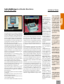
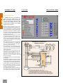
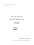
You Can Trust
Bulletin
210EE
VEC205E COMPACT AVR / EXCITER
GENERATOR STATIC EXCITER
K
N
A
L
B
VEC205D Series Static Exciters
BULLETIN 210D
COMPACTVAR
VEC205E
VEC 205E/1/50
The VEC 200 series is a family product that
include AVRs (Automatic Voltage Regulators) for Generators, Static Exciter and
Drivers for Synchronous Motors and Alternators, High Current Controlled Rectifiers or Simple 1 quadrant CC Motor Drive.
The VEC205E is an AVR Automatic Voltage Regulator/ Generator Static Exciter to
be used in all types of alternators.
The VEC205E utilizes IGBT (Insulated
Gate Bipolar Transistor) that dispenses sincronism in the exciting power inputs (A, B
and C) and enables the use of continuous
current supply like CC PMG (Permanent
Magnet Generator). The PWM control is
made at more than 1000 Hz frequency getting very low dead time.
The VEC205E is an economical, monoboard architecture, plug in, reliable and
good performance product.
The VEC205E has some incorporated functions and protections. The control signal
type could be chosen when ordering.
The voltage sensing is made synchronously by sample and hold integrated circuit, and
than averaged, which provides low second
order retard and fast response time.
The VEC205E has separated P + I + D
adjusts that together with the sensing characteristics enable it to operate virtually in
any machine. Five adjusts are available at
the front panel.
Seven LEDs signalizes its functions and fails
conditions.
Eight DIP Switches at front panel, simplifies the function selection.
The removable connector enables an easy
control module change.
The control module VEC205EC is the core
VEC205E + EXCITATION TRANSFORMER
of the system. Wen plugged to power module, from 10 to 1000 Ampere, forms the
final equipment, that could be an AVR, a
compact exciter, or if mounted inside a panel, with auxiliary equipment (like circuit
breaker, crowbar, fuses and transformers),
a complete Generator Static Exciter system.
The VEC205E is a good choice for reliable
and economical equipment, with a good
performance. The mono board architecture,
encapsulated Plug In modules allows high
tolerance to hostile environment and to vibrations besides allowing easy maintenance
with a simple module change. The power
semiconductors used are encapsulated insulated base types, highly reliable and allow clean assemblage and ease maintenace.
The control module uses a 3-phase or 2phase diode bridge with IGBT for the PWM
chopper.
There are two modes of KVAR compensation available for paralleling generators: by
an external power factor transducer or by
an internal power factor transducer included in module. The P.F. sensed by the Power Factor transducer is added to the voltage readings to get the Droop by Reactive
Power Factor Compensation” method.
The IGBT Firing Module are fully encapsulated in high insulation epoxy resins.
• Applications:
AVR and Static Exciter for Synchronous Alternators.
• Available control signal:
0 to 5 V, 0 to 10 V,
Potentiometer, 0 to
20 mA, 4 to 20 mA.
• Modes: Voltage
regulation with
Droop by KVAR
portion of the load
(Compound), allowing Reactive
Droop Compensation for parallel operated generators or
electric network
paralleling (Cogeneration).
Trips: Overvoltage, Underfrequency Overtemperature, and Loss of
signal.
• Signalizers:
Power On, Enable,
Droop, Signal Loss,
Overvoltage, Underfrequency and
Overtemperature.
Function Selections: Inhibit On
Fail, P.F. Internal/
External, P.F. Polarity, Setting Range
Wide/Narrow, Proportional Enable,
Proportional Integrative Enable, Derivative Enable and
Mode Automatic /
Manual.
Power: 3-phases or
2-phases diode
bridge rectifier and
PWM controler by
IGBT (Chopper).
Power can be supplyed by AC od CC
source.
The VEC205E
(series VEC 20X)
is a good choice
for generators
exciters. It can
be used as AVR /
exciter for generators with auxiliary mechanical
exciter or Brushless generator or
it can be a Power Static Exciter
for collector ring
generators.
It was developed
mainly to get
high reliability
and simplicity.
It can be applied
in machines to
30.000 KVA and
up.
The plug in
monoboard encapsulated architecture, allows
clean and reliable assemblage.
The LEDs signalization and
DIP switches
makes the equipment friendly
and intuitive. It
allows simple
commissioning
and use.
Five options of
input signals are
available.
Varix can supply
a complete line of
Exciter, including digitals programmable
models.
J3
COMPACTVAR
BULLETIN 210D
VEC205D
GENERATOR EXCITATION:
AVR (AUTOMATIC VOLTAGE REGULAV OLTAGE R EGULATOR FOR
BRUSCHLESS ALTERNATOR OR WITH EXTERNAL AUXILIARY ROTARY EXCITER TO 50
AMPERE FIELD CURRENT OR STATIC EXCITER FOR COLLECTOR RING TYPE TO 1000
AMPERE FIELD CURRENT:
•
TOR ):
J4
N R
S
MINIMUM CONNECTION
Simplified diagram
T
3 P HA SE S
PM G
E X CITA TIO N
T RA NS FO RM .
O R PM G
S E NS ING
T RA NS FO RM .
115 VCA
30 VA M IN .
P.T.s
S
T
A
B
R S T
A B
C
12
11
B2
B3
115 V
B4
5
B5
B6
7
3
F AN P.
S U PP LY
P O TENT .
500 O HM S
10
3
- P H AS E S - (O P TION ).
B UILD U P E NA BLE
FA IL
4
R EFER . O P T .
1
2
P O W E R - 115 /220 VCA/VCC
SEE TAG
Com .
N. O .
3
9
3
S EN S IN G P H A SE RT - O PT IO N .
MA
CC
PM G
B1
115 V
Fuses
C .T. IN /100
R S T
F U S ES
R
2 P HA SE S
PM G
+
VEC205EC
It allows keeping constant voltage at the
generator output and getting reactive current compensation in parallel operated
generators for KVAR sharing with another
machines or with the electrical supplier
network. The sharing of the reactive load
is made by Droop method based in the
machine Power Factor.
The Power Factor is digitally measured,
by means of signals from P.T. and C.T. in
the stator circuits or by an external transducer, like the GE Multilin SPM model.
In both cases the Droop rate can be adjusted from 0 to 5%.
The regulation mode can be selected by
an external command, to “Constant Voltage” or “Compound Voltage with Reactive Droop Compensation”.
The protections Loss of Signal, Generator Overvoltage, Generator Underspeed
and Exciter Overtemperature are active
in this application.
Some parameters can be adjusted in the
front panel: Proportional Gain (P - proportional action), Integrative Time (I Integrative action), Derivative time (D derivative action), Voltage scale and
Droop percentage.
Automatic Build Up with manual enabling
is available.
The mode of operation can be choused
Automatic or Manual. The manual operation can be used for a full range generator
voltage adjust, especially with auxiliary
power supply, for tests and characteristics measurement purpose or used in
emergency operation as a second channel
manual or manual follow up.
The Manual mode (or Drive mode) can
be used as a drive for an external regulator actuating at the setting range input.
B7
B8
6
EN AB LE
8
S IN GLE / P A RA LLEL
VEC 205E
(+)
(-)
G EN ER A TO R
(C O LE CTOR R ING
O R B R US HLES S )
N otes:
1: The C ircuit B reaker C B 2 and its conections
is not used in case off P M G - Perm anet M agnet G enerator.
2: The B uild U p E nable button is not used in case off use w ith PM G .
3: IF used w ith PM G w ith 2 Phases connect input T to gheter input R .
4: C o nnect Pow er Input (1 an d 2) to PM G if it’s vo ltage range is adequate.
5: A ll W ires to co nnector 3 (C om m om ) m ust be conn ecte d straight to it.
-
BULLETIN 210D
VEC205D
DIP SWITCHES SELECTIONS:
LEDS SIGNALIZATION:
FRONTAL PANEL ADJUSTS:
• S1- “Inhibition On Fail”: Selects the
Inhibition function of the output in case of
fail. If not selected the only action will be a
Fail Relay signalization.
• S2- “Droop Internal/External”: Selects the power factor transducer source for
Droop signal.
• S3- “Sensing Type”: Selects the type
of the sensing: “Sample & Hold” that provides fast response but is a lille sensitive to
wave distortions and “Average” that presents second order retard but is more insensitive to wave distortions).
• S4- “Setting Range Wide/Narrow”:
Selects setting range: narrow or wide (0 to
100% / +/- 10% of the scale).
• S5- “Proportional Gain”: Enables
the pure proportional gain error amplifier.
The value must be adjusted in the front panel
for the best response, without oscillations
and minimum overshoot and undershoot.
Normally used in almost all applications.
• S6- “Integrative Time”: Enables the
I portion of the error amplifier. The integrative time must be adjusted in the front
panel for the best stability and to get the
minimum overshoot, undershoot and the
fastest reaction time possible. Normally
used in almost all applications.
• S7- “Derivative Time”: Enables derivative gain error amplifier. The value must
be adjusted in the front panel for the fastest
reaction time, but without oscillations and
to get the minimum overshoot, and undershoot. Used in a few applications.
• S8- “Automatic/Manual or Regulator/Drive”: At “OFF” it selects the mode
“Automatic” (or Regulator), with regulation based in the error signal. At “ON” it
selects “Manual” (or Drive); it means that
the output is proportional only to setting
signal (reference). In this mode there is not
a local closed loop and the equipment is
simply a drive for external regulators or a
manual exciter.
• L1- “Inhibit”: (Yellow) - Signalizes
that the equipment is powered ON.
• L2- “Power Enable”: (Green) - Signalizes that the equipment is enabled by a
signal at corresponding connector.
• L3- “Droop Enable”: (Green) - Signalizes that there is a Droop command at
corresponding connector.
• L4- “Signal Loss”: (Red) - Signalizes
“Loss of Signal” (setting signal loss). This
function is enabled by the command signal
at corresponding connector. The condition
is memorized until a power down occurs.
• L5- “Overvoltage Trip” - (Red): Signalizes a trip by excess of generated voltage.
• L6- “Underfrequency Trip” - (Red):
Signalizes a trip by a machine underspeed.
• L7- “Overtemperature”: (Red) Signalizes an overtemperature condition in
the exciter power heater exchanger.
• P1- “Scale”: End of scale calibration
if a 100% setting range (Wide) is selected
at DIP S4, or to calibrate the nominal value
for medium of scale if a +/-10% (Narrow) setting range is selected at DIP S4.
• P2- “Droop”: Adjustable from 0 to
+5% Droop. The 5% compounding rate
is got with 90º rotor polar angle. Normally
used from 0 to 2.5% for parallel operating generators, maintaining the correct reactive load sharing. The compensation will
be initiated at Droop command. In single
generator system without cogeneration
this function is not used.
• P3- “Proportional Gain”: adjustable from 1 to 20. Active if selected at
corresponding DIP. How this is a pure
proportional amplifier, this adjust has influence in dynamic regulation and static
regulation. It must be adjusted to get the
fastest compensation of the input changes
but without instability.
• P4- “Integration Time”: This is a
integrative gain amplifier with integration
time adjustable from 0.01 to 1 S. Active
if selected at corresponding DIP. It must
be adjusted to get the best stability possible with minimum overshoot and undershoot. This portion of error amplifier is
mainly responsible for the static regulation and it must be selected in almost all
cases.
• P5- “Diferentiation Time”: adjustable from 0.01 to 1 S. Active if selected
at corresponding DIP. It allows a fast compensation of dynamic variations. Normally utilized for generators with slow response time. It must be adjusted to get
the fastest response and the best stability.
This portion of error amplifier is mainly
responsible for dynamic regulation.
Note: There is a 2 to 3 seconds time delay
to avoid erroneous tripping. The trip condition is memorized until a power down
occurs, if auxiliary power supply is used.
Otherwise, if “Inhibition on Fail” is selected
or relay signalization is used to trip the system, the indication will be lost. To reset a
memorized fail indication is necessary that
the module be powered off and powered
on again.
COMPACTVAR
J5
COMPACTVAR
VEC205D
CONTROL MODULE ELECTRICAL DATA:
The side table shows the electrical data of
the inputs and outputs of the control module, for both connectors (the front connector and the rear side DB15 connector).
Also some signals connected to the power
module (TB) are shown.
Some signals are chosen at order. This way
the various options are shown separated.
The type and real data are filled in a data
sheet that is sent with the equipment. The
data sheet shows some important information including signals, power components, date of delivery, guarantee period,
input and output data etc.
The user’s manual includes this bulletin,
electrical drawings, mechanical drawings,
and the custom data sheet.
TO P C O N N E C TO R
0 to 5 V S e tting
0 to 1 0 V S e tting
0 /4 to 2 0 m A S e tting
5 0 0 O hm s P o t S e ting
0 to 5 V P . F a c to r S yg na l
0 to 10 V P . F a c to r S yg na l
0 /4 to 2 0 m A P . F a c to r S .
E xt. P o w e r F a c to r Input
V o lta g e P ha se S e nsing
(Inte rna l P o w e r F a c to r)
V o lta g e P ha se S e nsing
(Inte rna l P o w e r F a c to r)
C urre nt P ha se S e nsing
(Inte rna l P o w e r F a c to r)
C urre nt P ha se S e nsing
(Inte rna l P o w e r F a c to r)
P o w e r E na ble Input
D ro o p E na ble Input
F a il R e la y C o nta c t
F a il R e la y C o nta c t
F a il R e la y C o nta c t
F a il R e la y C o nta c t
P o w e r S upply (1 1 5 / 2 2 0 )
P o w e r S upply
D B 1 5 C O N N E C TO R
O v e r Te m p. Input
(D ry C o nta c t N . C .)
S e nsing Input
F iring S ig na l
F iring S ig na l
TB / P O W E R
C O N N E C TO R
S e nsing
P o w e r / S inc ro
B uild U p E na ble
(D ry C o nta c t N . O .)
F a n P o w e r S upply
F a n P o w e r S upply
J6
BULLETIN 210D
B o rne s
X / Common
B4 / B3
B4 / B3
B4 / B3
B4 - B5 / B3
B7 / B3
B7 / B3
B7 / B3
B7 / B3
B9 / B3
M inim .
Inpu t Im pedance
Inpu t Im pedance
Inpu t Im pedance
O u tpu t C u rrent
Inpu t Im pedance
Inpu t Im pedance
Inpu t Im pedande
—
—
—
—
—
—
—
10 K
10 K
250
10
10 K
10 K
250
—
—
—
—
—
—
—
O hm s
O hm s
O hm s
mA
O hm s
O hm s
O hm s
Inpu t Im pedance
—
10 K
—
O hm s
B9 / B3
Inpu t V o ltage
20
115
150
V o lts
B10 / B3
Inpu t Im pedance
—
1
—
O hm s
B10 / B3
Inpu t C u rrent
0 ,1
—
1
Am per
B6 / B3
B8 / B3
B11 / B12
B10 / B11 / B12
B11 / B12
B11 / B12
B1 / B2
B1 / B2
C u rrent So u rce
C u rrent So u rce
V o ltage
V o ltage
C u rrent
C u rrent
V o ltage
P o w er
DB2 / DB1
S o u rce C u rrent
—
2 ,5
—
mA CC
D B 6 to D B 8 / D B 9 Inpu t V o ltage
D B 1 0 to D B 1 5 / D B 9 V o lts O u tpu t
D B 1 0 to D B 1 5 / D B 9 C u rrent O u tpu t
—
10
—
18
11
—
—
12
20
V AC
V o lts C C
mA CC
T B 1 to T B 3
R /S/T
TB 5 / TB 6
V o ltage Im pu t
V o ltage
C u rrent
TB 7 / TB 8
TB 7 / TB 8
V o ltage
P o w er
N o m ina l M a xim .
—
10
—
mA CC
—
10
—
mA CC
—
—
240
V AC
—
—
30
VCC
—
—
1
A AC
—
—
0 ,2 5
A CC
9 2 / 1 7 6 1 1 5 / 2 2 0 1 38 / 2 6 4 V A C / C C
—
4
—
W atts
9 2 / 1 7 6 1 1 5 / 2 2 0 1 38 / 2 6 4 V A C
30
—
254
V o lts
—
—
1
Am per
—
110 / 220
S ee Tag
—
V o lts
BULLETIN 210D
VEC205D
FUNCTION BY TYPE OF APPLICATION:
F U N C TIO N S
T Y PE / D E F A UT
D ISP O SIT IVE
0 TO 1 0 V OLTS S ET
0 TO 5 V OLTS SET
0 OR 4 TO 2 0 M A S ET
P O T E NT IO M E T E R S E T
1 0 0 % / 1 0 % S E T S E L E C T IO N
P R O P O R T IO N A L G A IN
1 TO 20
INT E G RA T IV E T IM E
T I = 0 .0 1 S T O 1 S
D E RIV AT IVE T IM E
T D = 0 .0 1 T O 1 S
P U R E V O L T AG E R E G U L A T IO N
R E AC IVE D RO O P C O M P E SA T IO N
S C AL E A DJ UST
INH IB IT IO N O N F AIL
S E NSIN G S E L E C T IO N
O ptio n
O ptio n
O ptio n
O ptio n
Select.
Select. / Adju st.
O pt.
O pt.
O pt.
O pt.
S4 O F F / O N
S5 O N / P 3
Select./Adju st.
S6 O N / P 4
Select./Adju st.
S7 O N / P 5
The side table shows the functions available, with the kind of action (selection or
adjust) and the range of adjust.
In case of trip, the output will be inhibited
(If S1 ON), the corresponding LED will be
turned on and the trip relay will be energized.
There is a time retard of approximately 0.5
seconds for the effective actuation of the
protection.
The error amplifier is a selectable P + I + D
type. Note that it is different of a unique
PID amplifier. This way it can be adapted
to virtually any process because its versatility. The user can select and adjust the response types needed.
The second portion, the “I” error amplifier, is mainly responsible for the static regulation. Its Integrative time is adjustable from
0.01 to 1 Seg. This portion of error amplifier needs to be selected in almost all applications.
The first portion of the error amplifier is a
pure proportional gain amplifier (P) and it
is mainly responsible for dynamic regulation. It is necessary in almost all applications, to increase the response and to get
fast corrections. It must be adjusted as high
as possible avoiding instability and yet getting fast response time with low overshoot
and undershoot.
The third portion of the error amplifier is a
pure derivative gain amplifier (D) and it is
mainly responsible for dynamic regulations.
It is necessary in a very few applications to
increase the stability and get fast corrections. It must be adjusted as low as possible to get stability and better response
time. Avoid use if it is not necessary.
COMPACTVAR
P O W E R F A CT O R S O URC E
D R O O P R A N G E ( A DJ . 0 - 5 % )
S E T IN G S IG N A L L O SS
O VE R V O L T A G E T RIP
U N DE RF R E Q U E N CY T RIP
O VE R T E M P E RA T U R E T R IP
D R O O P E NA B L E IND ICA T IO N
P O W E R E N AB L E IN DIC AT IO N
INH IB IT C O M M A ND IN DIC AT IO N
A U T O / M AN UA L S E L E C T IO N
M o del Nom in a l M axim .
VE C2 0 5 E / C u rren t C u rren t
( A ) (1 m in )
(A)
0025
0050
0100
0150
0200
0250
0300
0400
0500
0650
0750
1000
25
50
100
150
200
250
300
400
500
650
750
1000
50
100
200
300
400
500
600
800
1000
1300
1500
2000
Select
B 8 /B 3 O pen
Sel./Adj.0 to 1 0 % B 8 /B 3 C lo sed
Adju st
P1
Select
S1 O N
Sam ple & H o ld /
S3 O F F /O N
Average
Select Inter. / E xter. S2 O F F /O N
Select /Adju st
B 8 -B 3 / P 2
OK
L4
1 2 0 % / 0 .5 SE C .
L5
- 1 5 % / 2 SE C .
L6
9 0 ºC
L7
OK
L3
OK
L2
OK
L1
Select
S8 O F F / O N
Su rge C oolin g W id e Ta ll Lon g
C u rren t Forc./ ( W ) ( T ) ( L )
(1 0 m S) Na tu ral m m m m m m
(A)
100
200
400
600
800
1000
1200
1600
2000
2600
3000
4000
N
N
F
F
F
F
F
F
F
F
F
F
225
240
290
340
377
377
377
377
377
377
377
540
290
290
290
290
290
330
380
430
480
530
580
850
200
270
270
270
270
270
300
300
300
330
330
315
J7
COMPACTVAR
BULLETIN 210D
VEC205D
CONTROL MODULE VEC205DC
The side drawing shows the connections
to top connector and rear connector
(DB15) of the VEC205EC.
To connectors 1 and 2 are plugged to the
command power supply of 110 or 220
VAC depending off the model.
Connector 3 is the common connector for
all the inputs.
Connector 4 is the setting input. This input can be chosen at order (0 to 5 VCC
or 0 to 10 VCC or 500 Ohms or 10k Ohms
digital scale potentiometer, 0 to 20 mA
or 4 to 20 mA).
Connector 5 is a auxiliary current source
(10 mA) for direct use of a potentiometer
for setting range adjust (500 Ohms in a 5
VCC model or 1K ohms in a 10 VCC
model) This output must be tight to connector 4 for potentiometer use.
Connector 7 is the input for an optional
secondary input signal or Droop signal
(same signal options). This signal can be
provided by a Power Factor Transducer
(Ex: GE-Multilin SPM model), Hall effect sensor, tachogenerator, etc.
Connector 9 is the input for an optional
voltage transformer for power factor sensing (Polar Angle sensing), to get internal
generation of Droop signal.
Connector 10 is the input for an optional
current transformer for power factor sensing (Polar Angle sensing), to get for internal generation of Droop signal.
The connector 6 is the input for a dry contact for “Power Enable” command.
Connector 8 is the input for a dry contact
for the “Droop Enable” command.
Connectors 11 and 12 are the N.O. Dry
contact of the fail indication relay.
DB1 and DB9 are the common input connectors.
DB2 is input for a N.C. dry contact of a
temperature sensor (common at DB1).
Connectors DB6 to DB8 are the inputs
for voltage sensing signal (common at
DB9). Connectors DB10 to DB15 are the
outputs for the thyristors firing modules
(common at DB9).
Signals to connectors 4 / 5, 6, 7, 8 / 9 and
10 must be routed preferably with sepa-
J8
VEC205EC
1 110/220 VAC/VCC
See Tag
2 110/220 VAC/VCC
DB 1
COMMOM
DB 2
B IM ETALIC T E M PER ATURE (N.C.)
DB 3
3 COMMOM
500R
Transductor
T.P. Phase RT
T.C. PHAS. S
O PTIO NAL
S YG NA LS
B4 / B7
0 to 5 VCC
DB 4
4 S E TTING INP UT
DB 5
5 O UTPU T 10 M A
DB 6
S EN SING R
7 E X T . P. F A CTO R
S E NSING (O PT .)
9 I NT . P. F ACTO R
S E NSING (O PT .)
10 INT . P. F ACTO R
S ENSING (O P T .)
DB 7
S EN SING S
DB 8
S EN SING T
DB 9
"C O M M O N "
DB10
DB11
DB12
1 - F IRING
0 to 10 VCC
DB13
2- F IR IN G M O DU LE
0 to 20 m A
DB14
3- F IRING M O DULE O VER C UR .
4 to 20 m A
DB15
4- F IRING M O DULE O VER C UR .
E NABLE
D RO O P
F AIL
N. O .
COM.
M O DULE
6 P O W E R E N ABLE
8 D R O O P E NABLE
11
12
rated shielded cable with commom cable
connected straight to connector 3.
GENERATORS EXCITERS:
This application is for all types of alternators (“Collector Ring”, “Brushless” or
“Collector Ring” with auxiliary rotary
exciter).
IMPORTANT POINTS FOR WIRING AND START
U P:
• Select the DIP as required. Normally S1
ON, S2 ON, S3 ON, S4 ON, S5 ON, S6
ON and S7 OFF.
• The phasing at C.T. and P.T. at connectors 10/3 and 9/3 must be exactly as shown.
• The excitation transformer must have
adequate power and tension to get the correct ceiling voltage.
• The fuses must be ultra-fast types with
2
adequate i T (see data sheet).
• The sensing transformer (30 VA) must
be connected to point that must be regulated. The secondary nominal tension must be
115 VAC.
• The C.T. for power factor sensing must
be at correct motor power cable.
• The C.T. must have secondary rating of
100 mA to 1A (C.T. with secondary rate of
5 Ampere could damage the module).
• The P.T. for sensing the voltage phase
angle for internal power factor transducer
must be connected at the cables not used
for sensing the current phase angle (the
middle cable in this case). The nominal voltage is 115 VAC +10%, - 30%.
• If the user chooses to use an external
transducer for power factor, the transducer must supply the correct voltage to the
module, corresponding to total range, from
totally inductive to totally capacitive. The
center range voltage must be equal to unity
power factor.
• The control signals are commented at
control module drawing sheet.
• The excitation must be applied only at
nominal speed.
• At Start Up, before enabling definitively the Droop/Power Factor function, the
correct polarity of the signal should be verified by this way: You must load the generator in single mode (none paralleled) with
inductive loads to get at least 0,80 inductive P.F. with the Droop command closed
and . Short circuit the TC momentarily. The
output generator tension must increase a
little. Open the short in the TC. The Voltage must decrease a lille. If not, change the
polarity of the C.T. - In normal operation
the Droop command must be closed at all
times if parallel operation are used and
opened if parallel operatios are not used.
This way you avoid voltage umbalance at
Droop circuit in parallel operations and get
better static regulation in single mode.
The build up enable switch is used to enable the auto build up circuit. It must be a
momentary type switch. It is not used if
PMG is supplying the power.
Try operate at the two modes of “Sensing”
COMPACTVAR
VEC205D
R
S
APPLICATION EXAMPLE
T
CB1
2 P H ASES
PM G
3 P H ASES
PM G
E XCIT ATIO N
T R AN SFOR M .
CC
PM G
+
-
CB2
A B C
F USES
S EN SING
T RA NSF ORM .
115 VCA
30 VA M IN .
A
R'
S'
T'
B
B1
B2
B3
12
11
B4
B U ILD U P E NA BL E
1
2
10
3
C .T.
C R OW B AR V A RIX
O PT ION .
G EN ERA TOR
(C OL ECT OR R ING
OR B RU SHL ESS )
R EFER . O PT .
4
R EFER. O PT .
4
6
8
7
3
F A N P.
S U PPLY
B7
B8
+4
TO
+0
20
TO
MA
-
5V -
5
9
(+)
(-)
FA IL
P OT 500R
3
3
P OW ER F A CT OR
T RA NS DU CER
O PT ION .
A B
4
R EFER . O PT .
B6
S EN SIN G P HA SE RT - O PT ION .
C OM .
N . O.
3
B5
T R AN SFOR M . 115 / 220 VA C /VC C
O R PM G
115 / 220 VA C /VC C
30 VA M IN .
SEE TA G
C .T. IN /100 M A - P HA SE S - (O PT ION ).
A B C
C
VEC205EC
BULLETIN 210D
EN AB LE
D R OOP
VEC 205E
(+)
(-)
C1 O PTION .
C2 O PTION .
D ISCH AR GE
RESIST OR
O PT .
N otes:
1: The C ircuit B reaker C B 2 an d its con ections
is n ot used in case off P M G - P erm anet M agnet G en erator.
2: The B u ild U p Enable button is not used in case o ff use w ith P M G .
3: IF used w ith P M G w ith 2 P hases connect input T togheter inp ut R
4: C onn ect P ow er Inp ut (1 and 2) to P M G if it’s vo ltag e range is adequ ate.
5: The TC and T P at con nectors 10/3 and 9/3 substitutes the Pow er
Facto r Transducer at connector 7/3 for D roop purpo se.
6: A ll W ires to con nector 3 (C om m om ) m u st b e co nnected straig ht to it.
selected at DIP S3 and choose the one that
best adapts in your system. Prefer “Average” if is not apreciable diference because
it`s best insensity to wave distortion.
Operation Instructions: After the generator got the nominal speed, close the power enable switch. Then momentarily close
the Build Up Enable switch if the power is
supplyed from the generator. If the remnant
voltage of generator is at least 10 VAC, the
voltage will raise to near the nominal voltage. Adjust the nominal voltage if necessary (level pre defined at Start-Up). The
voltage needs not to be readjusted at any
time. Put the generator at bus (closing the
main circuit Breaker). If it is a multi generator system, the paralleling must be done
with a synchronism indicator/relay. The
Droop command contact must be closed
Share the active load (KVA) at turbine regulators. The AVRs will try to automatically
share the reactive load (KVAR). Avoid
changing the voltage setting of the regulators, to share ative loads. It can be necessary to readjust slightly the voltage of the
generators to share the reactive power at
the begining of the parallel operation only.
The loads must be shared proportionally
to the rated generator’s power.
Note: During the Start Up all the regulators must be adjusted with same Gain and
Droop.
The Droop rate must be as low as possible, mainly if the machines are identical.
Normally a 1% to 3% level is a good
choice.
To turn OFF one generator, first unload it
at speed regulators, then open the main
circuit breaker to get it out of the bus,
them inhibit it at “Power Enable” (open
the switch) and finally slow down the machine speed to zero.
Notes: 1- The diagram is a simplified version. 2- Is advisable that signal connections be made with shielded cables with
shield routed to connector 3.
J9
COMPACTVAR
BULLETIN 210D
VEC205D
ACCESSORIES:
COMPLETE SOLUTIONS FROM VARIX
• Ultra-Fast fuses.
• Power Transformers.
• Synchronism and sensing transformers.
• Shunt amplifier: VSA650A (60 mv/5V
insulated).
• Digital Potentiometer + Servo controller: VSP510A.
• Mult-turn potentiometer panel with digital scale: VP1020E.
• “Field Application Relay”: VR9045.
• “Field Ground Fault Relay”: VR9030A.
• “Field Over Voltage Relay”: VR9031A.
• “Step-Out Relay”: VR9035A.
• “Field Loss Relay”: VR9034A.
• Other protection relays.
• Control Box (M1 or M2).
• Crowbar.
VARIX or its integrators can offer complete
systems, including panels, circuit breakers,
fuses, instruments, GE Multilin Relays, PLC
and many others. The equipment can be
projected and dimensioned by our engineering personnel to satisfy the needs of the customer.
Our field personnel can provide the Start
Up.
STATIC EXCITER WITH VEC 205E,
SYNCHRONOUS GENERATOR
FOR
SPARE PARTS:
• Control Module:
VEC205EC/X/X/X/X/X. (See Order
Code Table)
• Firing Modules: VDE115A
• VV1 and VV2: - Fans - see custom data
sheet at manual.
• VRN1 and VRN2: - Thermostats - see
custom data sheet at manual.
• VC12: - 12 ways female connector.
• VS204/3E: - Synchronism module.
ORDER CODE
V E C 2 0 5 E /X /X X X X /X X X /X /X /X /X
A
A
B
C
B
C
D E F G
P O W ER SU P P LY
1 = 110 V C A
2 = 220 V C A
3 = O T H ER
C U R R EN T
N O M IN A L C U R R E N T
V O LTA G E
N O M IN A L V O LT A G E
S ETTIN G
1=
2=
3=
4=
0 TO
0 TO
4 TO
0 TO
5 V O LTS / P O T EN TIO M .
10 V O LTS / P O TE N TIO M .
20 m A .
20 m A .
1=
2=
3=
4=
0 TO
0 TO
4 TO
0 TO
5 V O LTS / P O T EN TIO M E T.
10 V O LTS / P O TE N TIO M .
20 m A .
20 m A .
D P O IN T
A D JU ST
EX T . P O W ER
E F A C TO R
SYG NAL
FAN
F V O LTA G E
0 = W /O F A N
1 = 120 V A C
2 = 220 V A C
E X A M PLE :
V E C 2 05E /1/00 50/150/ 1/2/0: G en erator Ex citer, C on trol
P ow er S upply: 110 V C A , N ominal Current: 50 A mper, N ominal V oltage: 150 V olts, S etting P oint A djust: 0 to 5 V C C or
P otentiometer, External P ow er F actor S ignal: 0 to 10 V C C ,
W /O F an.
J 10
VEC205E PLUG IN CONTROL MODULE
5000 KVA
K
N
A
L
B
Varix Brazil:
Rua Phelipe Zaidan Maluf 1501 - Distrito Industrial Unileste
Piracicaba - SP - CEP13.422.190 - Phone: (55) (19) 3424.4000 - Fax: (55) (19) 3424.4001
www.varix.com.br
e-mail: [email protected]
Varix Electronics USA:
10001 NW 50 Th Street - Bldg. 102-A
Fort
Lauderdale
Florida
33351
Tool Free: 1-800-238 6696 - Phone: (954) 572 5535 - Fax: (954) 572 0331
Quality System
ISO 9002 Certified
• STATICS EXCITERS FOR GENERATORS.
• STATICS EXCITERS FOR SYNCHRONOUS MOTORS.
• AVRS - AUTOMATIC VOLTAGE REGULATORS.
• SOFT STARTERS FOR MOTORS.
• POWER CONTROLLERS.
• SSCS - SOLID STATE CONTACTORS.
• CONTROLLED RECTIFIERS UP TO 150.000 A.
• CHOPPERS FOR MOTORS.
• PROTECTION RELAYS FOR EXCITATION SYSTEMS.
• DIGITAL RELAYS FOR CIRCUIT BREAKERS SUPERVISION.
• TRANSMITTERS AND TRANSDUCERS.
• SYNCHRONISM CONTROL BOX FOR SYNCHRONOUS MOTORS.
• CROWBAR FOR SYNCHRONOUS MOTORS.
• CROWBAR FOR TRANSIENT PROTECTION.
• SPECIAL EQUIPMENTS.