
1
Mai Tai Wideband, Mode-Locked Ti:Sapphire Laser User’s Manual 1335 Terra Bella Avenue Mountain View, CA 94043 Part Number 0000-315A, Rev. A June 2003 Preface This manual contains information you need in order to safely operate your Wideband Mai Tai™ laser. The “Unpacking and Inspection” section contains information on how to unpack your Mai Tai system and lists the items you should have received. It also lists any options you may have purchased. Please read this short, but important, section before you begin to unpack the rest of your unit. Please note that only personnel authorized and trained by Spectra-Physics may install the Mai Tai system. The “Introduction” contains a brief description of the Mai Tai laser, its power supply and the control devices. Following the Introduction is an important chapter on safety. The Mai Tai is a Class IV laser and, as such, emits laser radiation that can permanently damage eyes and skin. This section contains information about these hazards and offers suggestions on how to safeguard against them, as well as installation procedures and maintenance you must perform in order to keep your system in compliance with CDRH regulations. To ensure your system is installed according to CDRH regulations and to minimize the risk of injury or expensive repairs, be sure to read this chapter on Laser Safety—then follow these instructions. “Laser Description” contains a brief exposition on solid-state CW pumping and Titanium:sapphire laser theory. This is followed by a more detailed description of the Mai Tai laser system. The chapter concludes with system specifications and outline drawings. The next chapter describes the Mai Tai controls and is followed by a chapter that describes how to prepare your site for the installation of the system and the installation of the control software. Chapter 6 contains procedures for operating the laser, including descriptions of the Windows-based GUI interface provided with the system and the command/query structure required for writing your own control program. The last part of the manual covers available options, maintenance and service, including a replacement parts list. Should you experience any problems with any equipment purchased from Spectra-Physics, or you are in need of technical information or support, please contact Spectra-Physics as described in “Customer Service.” This chapter contains a list of world-wide Spectra-Physics Service Centers you can call if you need help. iii Mai Tai Wideband, Mode-Locked Ti:sapphire Laser Appendix A provides information on short pulse formation in the modelocked Mai Tai laser, while Appendix B provides general information on pulse width measurement. Appendix C lists the status and error codes that might be generated by the system. This product has been tested and found to conform to the provisions of Directive 73/23/EEC governing product safety using the EN 61010-1: 2001 and EN 60825-1: 1994 standards, and the provisions of Directive 89/336/ EEC governing electromagnetic compatibility using the EN 61326-1 w/A1: 1997 standard. Refer to the “EC Declaration of Conformity” in Chapter 2, “Laser Safety.” This product conforms to the requirements of 21 CFR 1040.10 CDRH and is compliant to Underwriters Laboratory UL1950 and is listed as ULR for recognized components. This equipment has been designed and tested to comply with the limits for a Class A digital device pursuant to Part 15 of the FCC Rules. Every effort has been made to ensure that the information in this manual is accurate. All information in this document is subject to change without notice. Spectra-Physics makes no representation or warranty, either express or implied, with respect to this document. In no event will Spectra-Physics be liable for any direct, indirect, special, incidental or consequential damages resulting from any defects in this documentation. If you encounter any difficulty with the content or style of this manual, please let us know. The last page is a form to aid in bringing such problems to our attention. Thank you for your purchase of Spectra-Physics instruments. iv Environmental Specifications CE Electrical Equipment Requirements For information regarding the equipment needed to provide the electrical service listed under “Service Requirements” at the end of Chapter 3, please refer to specification EN-309, “Plug, Outlet and Socket Couplers for Industrial Uses,” listed in the official Journal of the European Communities. Environmental Specifications The environmental conditions under which the laser system will function are listed below: Indoor use Altitude: up to 2000 m Temperatures: 10° C to 40° C Maximum relative humidity: 80% non-condensing for temperatures up to 31° C. Mains supply voltage: do not exceed ±10% of the nominal voltage Insulation category: II Pollution degree: 2 FCC Regulations This equipment has been tested and found to comply with the limits for a Class A digital device pursuant to Part 15 of the FCC Rules. These limits are designed to provide reasonable protection against harmful interference when the equipment is operated in a commercial environment. This equipment generates, uses and can radiate radio frequency energy and, if not installed and used in accordance with the instruction manual, may cause harmful interference to radio communications. Operation of this equipment in a residential area is likely to cause harmful interference in which case the user will be required to correct the interference at his own expense. Modifications to the laser system not expressly approved by Spectra-Physics could void your right to operate the equipment. v Table of Contents Preface . . . . . . . . . . . . . . . . . . . . . . . . . . . . . . . . . . . . . . . . . . . . . . . . . . . . . . . . . . . . . . iii Environmental Specifications. . . . . . . . . . . . . . . . . . . . . . . . . . . . . . . . . . . . . . . . . . . . v CE Electrical Equipment Requirements . . . . . . . . . . . . . . . . . . . . . . . . . . . . . . . . . . . . . . . . . . . . . . . . v Environmental Specifications . . . . . . . . . . . . . . . . . . . . . . . . . . . . . . . . . . . . . . . . . . . . . . . . . . . . . . . . v FCC Regulations . . . . . . . . . . . . . . . . . . . . . . . . . . . . . . . . . . . . . . . . . . . . . . . . . . . . . . . . . . . . . . . . . v Warning Conventions . . . . . . . . . . . . . . . . . . . . . . . . . . . . . . . . . . . . . . . . . . . . . . . . . . xiii Standard Units . . . . . . . . . . . . . . . . . . . . . . . . . . . . . . . . . . . . . . . . . . . . . . . . . . . . . . . . xv Abbreviations . . . . . . . . . . . . . . . . . . . . . . . . . . . . . . . . . . . . . . . . . . . . . . . . . . . . . . . . . xvii Unpacking and Inspection . . . . . . . . . . . . . . . . . . . . . . . . . . . . . . . . . . . . . . . . . . . . . . xix Unpacking Your Laser . . . . . . . . . . . . . . . . . . . . . . . . . . . . . . . . . . . . . . . . . . . . . . . . . . . . . . . . . . . . . xix System Components . . . . . . . . . . . . . . . . . . . . . . . . . . . . . . . . . . . . . . . . . . . . . . . . . . . . . . . . . . . . . . xix Accessory Kit . . . . . . . . . . . . . . . . . . . . . . . . . . . . . . . . . . . . . . . . . . . . . . . . . . . . . . . . . . . . . . . . . . . . xx Chapter 1: Introduction . . . . . . . . . . . . . . . . . . . . . . . . . . . . . . . . . . . . . . . . . . . . . . . . . 1-1 The Mai Tai Laser System . . . . . . . . . . . . . . . . . . . . . . . . . . . . . . . . . . . . . . . . . . . . . . . . . . . . . . . . . . 1-1 The CW Pump Chamber . . . . . . . . . . . . . . . . . . . . . . . . . . . . . . . . . . . . . . . . . . . . . . . . . . . . . . . . . . . 1-2 The Pulsed Output Chamber . . . . . . . . . . . . . . . . . . . . . . . . . . . . . . . . . . . . . . . . . . . . . . . . . . . . . . . . 1-2 Patents . . . . . . . . . . . . . . . . . . . . . . . . . . . . . . . . . . . . . . . . . . . . . . . . . . . . . . . . . . . . . . . . . . . . . . . . . 1-3 Chapter 2: Laser Safety. . . . . . . . . . . . . . . . . . . . . . . . . . . . . . . . . . . . . . . . . . . . . . . . . 2-1 Precautions for the Safe Operation of Class IV-High Power Lasers . . . . . . . . . . . . . . . . . . . . . . . . . . 2-1 Safety Devices . . . . . . . . . . . . . . . . . . . . . . . . . . . . . . . . . . . . . . . . . . . . . . . . . . . . . . . . . . . . . . . . . . . 2-3 Emission Indicators . . . . . . . . . . . . . . . . . . . . . . . . . . . . . . . . . . . . . . . . . . . . . . . . . . . . . . . . . . . . 2-3 Shutter . . . . . . . . . . . . . . . . . . . . . . . . . . . . . . . . . . . . . . . . . . . . . . . . . . . . . . . . . . . . . . . . . . . . . . 2-4 Cover Safety Interlocks . . . . . . . . . . . . . . . . . . . . . . . . . . . . . . . . . . . . . . . . . . . . . . . . . . . . . . . . . 2-4 Interlock Keyswitch . . . . . . . . . . . . . . . . . . . . . . . . . . . . . . . . . . . . . . . . . . . . . . . . . . . . . . . . . . . . 2-5 POWER Switch . . . . . . . . . . . . . . . . . . . . . . . . . . . . . . . . . . . . . . . . . . . . . . . . . . . . . . . . . . . . . . . 2-5 POWER Indicator . . . . . . . . . . . . . . . . . . . . . . . . . . . . . . . . . . . . . . . . . . . . . . . . . . . . . . . . . . . . . 2-5 Safety Interlock . . . . . . . . . . . . . . . . . . . . . . . . . . . . . . . . . . . . . . . . . . . . . . . . . . . . . . . . . . . . . . . 2-5 CDRH Requirements for Operating the Mai Tai . . . . . . . . . . . . . . . . . . . . . . . . . . . . . . . . . . . . . . . . . . 2-6 Maintenance Necessary to Keep this Laser Product in Compliance with Center for Devices and Radiological Health (CDRH) Regulations . . . . . . . . . . . . . . . . . . . . . . . . . . . . . . . . . 2-6 CE/CDRH Radiation Control Drawings . . . . . . . . . . . . . . . . . . . . . . . . . . . . . . . . . . . . . . . . . . . . . . . . 2-7 CE/CDRH Warning Labels . . . . . . . . . . . . . . . . . . . . . . . . . . . . . . . . . . . . . . . . . . . . . . . . . . . . . . . . . . 2-10 Label Translations . . . . . . . . . . . . . . . . . . . . . . . . . . . . . . . . . . . . . . . . . . . . . . . . . . . . . . . . . . . . . 2-11 CE Declaration of Conformity . . . . . . . . . . . . . . . . . . . . . . . . . . . . . . . . . . . . . . . . . . . . . . . . . . . . . . . . 2-12 vii Mai Tai Wideband, Mode-Locked Ti:sapphire Laser Sources for Additional Information . . . . . . . . . . . . . . . . . . . . . . . . . . . . . . . . . . . . . . . . . . . . . . . . . . . .2-13 Laser Safety Standards . . . . . . . . . . . . . . . . . . . . . . . . . . . . . . . . . . . . . . . . . . . . . . . . . . . . . . . . .2-13 Equipment and Training . . . . . . . . . . . . . . . . . . . . . . . . . . . . . . . . . . . . . . . . . . . . . . . . . . . . . . . . .2-14 Chapter 3: Laser Description . . . . . . . . . . . . . . . . . . . . . . . . . . . . . . . . . . . . . . . . . . . . 3-1 A Brief Review of Laser Theory . . . . . . . . . . . . . . . . . . . . . . . . . . . . . . . . . . . . . . . . . . . . . . . . . . . . . .3-1 Emission and Absorption of Light . . . . . . . . . . . . . . . . . . . . . . . . . . . . . . . . . . . . . . . . . . . . . . . . . .3-1 Population Inversion . . . . . . . . . . . . . . . . . . . . . . . . . . . . . . . . . . . . . . . . . . . . . . . . . . . . . . . . . . . .3-2 Resonant Optical Cavity . . . . . . . . . . . . . . . . . . . . . . . . . . . . . . . . . . . . . . . . . . . . . . . . . . . . . . . . . . . .3-4 Nd3+ as a Laser Medium . . . . . . . . . . . . . . . . . . . . . . . . . . . . . . . . . . . . . . . . . . . . . . . . . . . . . . . .3-5 Diode-pumped Laser Design . . . . . . . . . . . . . . . . . . . . . . . . . . . . . . . . . . . . . . . . . . . . . . . . . . . . .3-6 Frequency Doubling . . . . . . . . . . . . . . . . . . . . . . . . . . . . . . . . . . . . . . . . . . . . . . . . . . . . . . . . . . . .3-8 Ti:Sapphire as a Laser Medium . . . . . . . . . . . . . . . . . . . . . . . . . . . . . . . . . . . . . . . . . . . . . . . . . . .3-10 Pumping Optimization . . . . . . . . . . . . . . . . . . . . . . . . . . . . . . . . . . . . . . . . . . . . . . . . . . . . . . . . . .3-11 The Mai Tai CW Pump Chamber . . . . . . . . . . . . . . . . . . . . . . . . . . . . . . . . . . . . . . . . . . . . . . . . . . . . .3-12 General . . . . . . . . . . . . . . . . . . . . . . . . . . . . . . . . . . . . . . . . . . . . . . . . . . . . . . . . . . . . . . . . . . . . .3-12 Frequency Doubling . . . . . . . . . . . . . . . . . . . . . . . . . . . . . . . . . . . . . . . . . . . . . . . . . . . . . . . . . . . .3-12 Beam Delivery . . . . . . . . . . . . . . . . . . . . . . . . . . . . . . . . . . . . . . . . . . . . . . . . . . . . . . . . . . . . . . . .3-13 The Mai Tai Pulsed Output Chamber . . . . . . . . . . . . . . . . . . . . . . . . . . . . . . . . . . . . . . . . . . . . . . . . . .3-13 The Folded Cavity . . . . . . . . . . . . . . . . . . . . . . . . . . . . . . . . . . . . . . . . . . . . . . . . . . . . . . . . . . . . .3-13 Mode Locking Device . . . . . . . . . . . . . . . . . . . . . . . . . . . . . . . . . . . . . . . . . . . . . . . . . . . . . . . . . . .3-14 Wavelength Tuning Characteristics . . . . . . . . . . . . . . . . . . . . . . . . . . . . . . . . . . . . . . . . . . . . . . . .3-14 Wavelength Selection and Pulse Width . . . . . . . . . . . . . . . . . . . . . . . . . . . . . . . . . . . . . . . . . . . . .3-14 The Model J80 Power Supply . . . . . . . . . . . . . . . . . . . . . . . . . . . . . . . . . . . . . . . . . . . . . . . . . . . . . . . .3-15 The FCbar System . . . . . . . . . . . . . . . . . . . . . . . . . . . . . . . . . . . . . . . . . . . . . . . . . . . . . . . . . . . . .3-15 The Control Software . . . . . . . . . . . . . . . . . . . . . . . . . . . . . . . . . . . . . . . . . . . . . . . . . . . . . . . . . . . . . .3-15 Specifications . . . . . . . . . . . . . . . . . . . . . . . . . . . . . . . . . . . . . . . . . . . . . . . . . . . . . . . . . . . . . . . . . . . .3-16 Typical Tuning Curve . . . . . . . . . . . . . . . . . . . . . . . . . . . . . . . . . . . . . . . . . . . . . . . . . . . . . . . . . . .3-17 Outline Drawings . . . . . . . . . . . . . . . . . . . . . . . . . . . . . . . . . . . . . . . . . . . . . . . . . . . . . . . . . . . . . .3-18 Chapter 4: Controls, Indicators and Connections . . . . . . . . . . . . . . . . . . . . . . . . . . . 4-1 Introduction . . . . . . . . . . . . . . . . . . . . . . . . . . . . . . . . . . . . . . . . . . . . . . . . . . . . . . . . . . . . . . . . . . . . . .4-1 The Mai Tai Laser Head . . . . . . . . . . . . . . . . . . . . . . . . . . . . . . . . . . . . . . . . . . . . . . . . . . . . . . . . . . . .4-1 Controls . . . . . . . . . . . . . . . . . . . . . . . . . . . . . . . . . . . . . . . . . . . . . . . . . . . . . . . . . . . . . . . . . . . . .4-1 Indicators . . . . . . . . . . . . . . . . . . . . . . . . . . . . . . . . . . . . . . . . . . . . . . . . . . . . . . . . . . . . . . . . . . . .4-1 Connections . . . . . . . . . . . . . . . . . . . . . . . . . . . . . . . . . . . . . . . . . . . . . . . . . . . . . . . . . . . . . . . . . .4-1 The Model J80 Power Supply . . . . . . . . . . . . . . . . . . . . . . . . . . . . . . . . . . . . . . . . . . . . . . . . . . . . . . . .4-3 Front Panel . . . . . . . . . . . . . . . . . . . . . . . . . . . . . . . . . . . . . . . . . . . . . . . . . . . . . . . . . . . . . . . . . . .4-3 Rear Panel . . . . . . . . . . . . . . . . . . . . . . . . . . . . . . . . . . . . . . . . . . . . . . . . . . . . . . . . . . . . . . . . . . .4-4 Connector Interface Descriptions . . . . . . . . . . . . . . . . . . . . . . . . . . . . . . . . . . . . . . . . . . . . . . . . . . . . .4-5 SERIAL COM Port Connector . . . . . . . . . . . . . . . . . . . . . . . . . . . . . . . . . . . . . . . . . . . . . . . . . . . .4-5 EMISSION Connector . . . . . . . . . . . . . . . . . . . . . . . . . . . . . . . . . . . . . . . . . . . . . . . . . . . . . . . . . .4-6 Safety INTERLOCK Connector . . . . . . . . . . . . . . . . . . . . . . . . . . . . . . . . . . . . . . . . . . . . . . . . . . .4-6 The Chiller . . . . . . . . . . . . . . . . . . . . . . . . . . . . . . . . . . . . . . . . . . . . . . . . . . . . . . . . . . . . . . . . . . . . . .4-6 Chapter 5: Installation. . . . . . . . . . . . . . . . . . . . . . . . . . . . . . . . . . . . . . . . . . . . . . . . . . 5-1 Moving the Laser System . . . . . . . . . . . . . . . . . . . . . . . . . . . . . . . . . . . . . . . . . . . . . . . . . . . . . . . . . . .5-1 Installing the Mai Tai Laser Head . . . . . . . . . . . . . . . . . . . . . . . . . . . . . . . . . . . . . . . . . . . . . . . . . . . . .5-1 Installing the Chiller and the Power Supply into the Rack . . . . . . . . . . . . . . . . . . . . . . . . . . . . . . . . . .5-2 Connecting the Chiller . . . . . . . . . . . . . . . . . . . . . . . . . . . . . . . . . . . . . . . . . . . . . . . . . . . . . . . . . . . . .5-5 Connecting the Mai Tai . . . . . . . . . . . . . . . . . . . . . . . . . . . . . . . . . . . . . . . . . . . . . . . . . . . . . . . . . . . . .5-6 Installing the Computer . . . . . . . . . . . . . . . . . . . . . . . . . . . . . . . . . . . . . . . . . . . . . . . . . . . . . . . . . . . . .5-8 Installing the LabWindows Control Software . . . . . . . . . . . . . . . . . . . . . . . . . . . . . . . . . . . . . . . . .5-8 viii Table of Contents Chapter 6: Operation . . . . . . . . . . . . . . . . . . . . . . . . . . . . . . . . . . . . . . . . . . . . . . . . . . . 6-1 Using the Chiller . . . . . . . . . . . . . . . . . . . . . . . . . . . . . . . . . . . . . . . . . . . . . . . . . . . . . . . . . . . . . . . . . . 6-1 Operating the System Using the LabWindows Software . . . . . . . . . . . . . . . . . . . . . . . . . . . . . . . . . . . 6-2 The Main Menu . . . . . . . . . . . . . . . . . . . . . . . . . . . . . . . . . . . . . . . . . . . . . . . . . . . . . . . . . . . . . . . 6-2 The Setup Menu . . . . . . . . . . . . . . . . . . . . . . . . . . . . . . . . . . . . . . . . . . . . . . . . . . . . . . . . . . . . . . 6-4 The Info Menu . . . . . . . . . . . . . . . . . . . . . . . . . . . . . . . . . . . . . . . . . . . . . . . . . . . . . . . . . . . . . . . . 6-5 The Scan Menu . . . . . . . . . . . . . . . . . . . . . . . . . . . . . . . . . . . . . . . . . . . . . . . . . . . . . . . . . . . . . . . 6-6 Turning the System On and Off . . . . . . . . . . . . . . . . . . . . . . . . . . . . . . . . . . . . . . . . . . . . . . . . . . . . . . 6-7 The RS-232 Serial Port . . . . . . . . . . . . . . . . . . . . . . . . . . . . . . . . . . . . . . . . . . . . . . . . . . . . . . . . . . . . 6-10 Pinout/Wiring . . . . . . . . . . . . . . . . . . . . . . . . . . . . . . . . . . . . . . . . . . . . . . . . . . . . . . . . . . . . . . . . . 6-10 Communications Parameters . . . . . . . . . . . . . . . . . . . . . . . . . . . . . . . . . . . . . . . . . . . . . . . . . . . . 6-10 Command/Query/Response Format . . . . . . . . . . . . . . . . . . . . . . . . . . . . . . . . . . . . . . . . . . . . . . . . . . 6-10 Typical Command Usage . . . . . . . . . . . . . . . . . . . . . . . . . . . . . . . . . . . . . . . . . . . . . . . . . . . . . . . 6-11 Commands and Queries Used by the Mai Tai . . . . . . . . . . . . . . . . . . . . . . . . . . . . . . . . . . . . . . . . . . . 6-12 Quick Reference . . . . . . . . . . . . . . . . . . . . . . . . . . . . . . . . . . . . . . . . . . . . . . . . . . . . . . . . . . . . . . 6-12 Full Description . . . . . . . . . . . . . . . . . . . . . . . . . . . . . . . . . . . . . . . . . . . . . . . . . . . . . . . . . . . . . . . 6-13 Chapter 7: Customer Service . . . . . . . . . . . . . . . . . . . . . . . . . . . . . . . . . . . . . . . . . . . . 7-1 Warranty . . . . . . . . . . . . . . . . . . . . . . . . . . . . . . . . . . . . . . . . . . . . . . . . . . . . . . . . . . . . . . . . . . . . . . . . 7-1 Return of the Instrument for Repair . . . . . . . . . . . . . . . . . . . . . . . . . . . . . . . . . . . . . . . . . . . . . . . . . . . 7-2 Service Centers . . . . . . . . . . . . . . . . . . . . . . . . . . . . . . . . . . . . . . . . . . . . . . . . . . . . . . . . . . . . . . . . . . 7-3 Appendix A: Modelocking. . . . . . . . . . . . . . . . . . . . . . . . . . . . . . . . . . . . . . . . . . . . . . . A-1 General . . . . . . . . . . . . . . . . . . . . . . . . . . . . . . . . . . . . . . . . . . . . . . . . . . . . . . . . . . . . . . . . . . . . . . . . A-1 Modelocking Techniques . . . . . . . . . . . . . . . . . . . . . . . . . . . . . . . . . . . . . . . . . . . . . . . . . . . . . . . . . . . A-2 Regenerative Modelocking . . . . . . . . . . . . . . . . . . . . . . . . . . . . . . . . . . . . . . . . . . . . . . . . . . . . . . . . . . A-4 Group Velocity Dispersion . . . . . . . . . . . . . . . . . . . . . . . . . . . . . . . . . . . . . . . . . . . . . . . . . . . . . . . . . . A-5 Nonlinear Effects . . . . . . . . . . . . . . . . . . . . . . . . . . . . . . . . . . . . . . . . . . . . . . . . . . . . . . . . . . . . . . A-6 GVD Compensation . . . . . . . . . . . . . . . . . . . . . . . . . . . . . . . . . . . . . . . . . . . . . . . . . . . . . . . . . . . . . . . A-7 Appendix B: Pulse Width Measurement . . . . . . . . . . . . . . . . . . . . . . . . . . . . . . . . . . . B-1 Introduction . . . . . . . . . . . . . . . . . . . . . . . . . . . . . . . . . . . . . . . . . . . . . . . . . . . . . . . . . . . . . . . . . . . . . B-1 The Autocorrelation Technique . . . . . . . . . . . . . . . . . . . . . . . . . . . . . . . . . . . . . . . . . . . . . . . . . . . . . . B-1 Measurement of Ultrashort Pulses . . . . . . . . . . . . . . . . . . . . . . . . . . . . . . . . . . . . . . . . . . . . . . . . B-1 Signal Interpretation . . . . . . . . . . . . . . . . . . . . . . . . . . . . . . . . . . . . . . . . . . . . . . . . . . . . . . . . . . . . . . . B-3 GVD Compensation in Measurement of Ultrashort Pulses . . . . . . . . . . . . . . . . . . . . . . . . . . . . . . . . . B-4 Calculating Pulse Broadening . . . . . . . . . . . . . . . . . . . . . . . . . . . . . . . . . . . . . . . . . . . . . . . . . . . . . . . B-6 Appendix C: Status Codes . . . . . . . . . . . . . . . . . . . . . . . . . . . . . . . . . . . . . . . . . . . . . . C-1 Notes Report Form for Problems and Solutions ix Mai Tai Wideband, Mode-Locked Ti:sapphire Laser List of Figures Figure 1-1: The scientific version of the Mai Tai Ti:sapphire mode-locked laser system . . . . . . . . . . .1-1 Figure 2-1: CDRH and CE standard safety warning labels . . . . . . . . . . . . . . . . . . . . . . . . . . . . . . . . .2-2 Figure 2-2: Folded Metal Beam Target . . . . . . . . . . . . . . . . . . . . . . . . . . . . . . . . . . . . . . . . . . . . . . . . .2-2 Figure 2-3: Laser Head Emission Indicator . . . . . . . . . . . . . . . . . . . . . . . . . . . . . . . . . . . . . . . . . . . . .2-3 Figure 2-4: The EMISSION Connector Schematic . . . . . . . . . . . . . . . . . . . . . . . . . . . . . . . . . . . . . . . .2-3 Figure 2-5: The Model J80 Safety Devices. . . . . . . . . . . . . . . . . . . . . . . . . . . . . . . . . . . . . . . . . . . . . .2-4 Figure 2-6: Interlock Jumper Plug . . . . . . . . . . . . . . . . . . . . . . . . . . . . . . . . . . . . . . . . . . . . . . . . . . . .2-5 Figure 2-7: CE/CDRH Radiation Control Drawing, OEM Version . . . . . . . . . . . . . . . . . . . . . . . . . . . . .2-7 Figure 2-8: CE/CDRH Radiation Control Drawing, Scientific Version . . . . . . . . . . . . . . . . . . . . . . . . . .2-8 Figure 2-9: CE/CDRH Radiation Control Drawing, Model J80 Power Supply . . . . . . . . . . . . . . . . . . . .2-9 Figure 2-10: CE/CDRH Warning Labels . . . . . . . . . . . . . . . . . . . . . . . . . . . . . . . . . . . . . . . . . . . . . . . .2-10 Figure 3-1: Electron orbitals . . . . . . . . . . . . . . . . . . . . . . . . . . . . . . . . . . . . . . . . . . . . . . . . . . . . . . . . .3-2 Figure 3-2: A Typical Four-level Transition Scheme . . . . . . . . . . . . . . . . . . . . . . . . . . . . . . . . . . . . . .3-3 Figure 3-3: Frequency Distribution of Longitudinal Modes for a Single Line . . . . . . . . . . . . . . . . . . . .3-4 Figure 3-4: Energy Level Scheme for the Nd3+ Ion. . . . . . . . . . . . . . . . . . . . . . . . . . . . . . . . . . . . . . . .3-5 Figure 3-5: Nd3+ absorption spectra . . . . . . . . . . . . . . . . . . . . . . . . . . . . . . . . . . . . . . . . . . . . . . . . . . .3-6 Figure 3-6: Mode Matching . . . . . . . . . . . . . . . . . . . . . . . . . . . . . . . . . . . . . . . . . . . . . . . . . . . . . . . . . .3-7 Figure 3-7: The quiet multiaxial mode-doubling (QMAD) solution to the “green problem.” . . . . . . . . .3-9 Figure 3-8: Absorption and Emission Spectra of Ti:Sapphire . . . . . . . . . . . . . . . . . . . . . . . . . . . . . . . .3-10 Figure 3-9: Energy Level Structure of Ti3+ in Sapphire . . . . . . . . . . . . . . . . . . . . . . . . . . . . . . . . . . . .3-11 Figure 3-10: Wideband Mai Tai Tuning Curve . . . . . . . . . . . . . . . . . . . . . . . . . . . . . . . . . . . . . . . . . . .3-17 Figure 3-11: Outline Drawing, OEM and Scientific Mai Tai Laser Heads . . . . . . . . . . . . . . . . . . . . . . .3-18 Figure 3-12: Outline Drawing, Mai Tai Power Supply (Model J80) . . . . . . . . . . . . . . . . . . . . . . . . . . . .3-19 Figure 3-13: Outline Drawing, Rack . . . . . . . . . . . . . . . . . . . . . . . . . . . . . . . . . . . . . . . . . . . . . . . . . . .3-19 Figure 4-1: The umbilical attachment panel showing the 40 MHz and 80 MHz BNC connectors. . . . .4-1 Figure 4-2: Sample waveform supplied by the 40 MHz connector . . . . . . . . . . . . . . . . . . . . . . . . . . . .4-2 Figure 4-3: Sample waveform from the 80 MHz connector into a 50 W oscilloscope input. . . . . . . . .4-2 Figure 4-4: The Model J80 Power Supply Front Panel . . . . . . . . . . . . . . . . . . . . . . . . . . . . . . . . . . . . .4-3 Figure 4-5: The Model J80 Power Supply Rear Panel . . . . . . . . . . . . . . . . . . . . . . . . . . . . . . . . . . . . .4-4 Figure 4-6: The ANALOG Jumper Plug . . . . . . . . . . . . . . . . . . . . . . . . . . . . . . . . . . . . . . . . . . . . . . . .4-4 Figure 4-7: The 9-Pin SERIAL COM Port . . . . . . . . . . . . . . . . . . . . . . . . . . . . . . . . . . . . . . . . . . . . . . .4-5 Figure 4-8: Model J80 Emission Connector Circuit . . . . . . . . . . . . . . . . . . . . . . . . . . . . . . . . . . . . . . .4-6 Figure 5-1: The Mounting Rail Notch on the Rack Base . . . . . . . . . . . . . . . . . . . . . . . . . . . . . . . . . . .5-3 Figure 5-2: The Chiller Set on the Base Facing the Two Notches . . . . . . . . . . . . . . . . . . . . . . . . . . . .5-3 Figure 5-3: The Chiller and a Power Supply Sitting on the Base . . . . . . . . . . . . . . . . . . . . . . . . . . . . .5-3 Figure 5-4: One End of the Vertical Rack Showing the Locking Bolt (upper bolt) . . . . . . . . . . . . . . . .5-4 Figure 5-5: The Power Supply and Chiller in the Rack . . . . . . . . . . . . . . . . . . . . . . . . . . . . . . . . . . . . .5-5 Figure 5-6: The Model J80 Interconnect Drawing . . . . . . . . . . . . . . . . . . . . . . . . . . . . . . . . . . . . . . . .5-6 Figure 5-7: The REMOTE Connector on the Power Supply Front Panel . . . . . . . . . . . . . . . . . . . . . . .5-6 Figure 5-8: Model J80 Rear Panel Connectors . . . . . . . . . . . . . . . . . . . . . . . . . . . . . . . . . . . . . . . . . .5-7 Figure 5-9: The EMISSION Connector Schematic . . . . . . . . . . . . . . . . . . . . . . . . . . . . . . . . . . . . . . . .5-7 Figure 6-1: The Main Menu . . . . . . . . . . . . . . . . . . . . . . . . . . . . . . . . . . . . . . . . . . . . . . . . . . . . . . . . .6-2 Figure 6-2: The Setup Menu . . . . . . . . . . . . . . . . . . . . . . . . . . . . . . . . . . . . . . . . . . . . . . . . . . . . . . . . .6-4 Figure 6-3: The Info Menu . . . . . . . . . . . . . . . . . . . . . . . . . . . . . . . . . . . . . . . . . . . . . . . . . . . . . . . . . .6-5 Figure 6-4: The Scan Menu . . . . . . . . . . . . . . . . . . . . . . . . . . . . . . . . . . . . . . . . . . . . . . . . . . . . . . . . .6-6 Figure 6-5: The Com Port (SERIAL COM) Setup Menu . . . . . . . . . . . . . . . . . . . . . . . . . . . . . . . . . . . .6-8 Figure A-1: Typical output of a mode-locked laser . . . . . . . . . . . . . . . . . . . . . . . . . . . . . . . . . . . . . . . .A-2 Figure A-2: Active modelocking using an AOM . . . . . . . . . . . . . . . . . . . . . . . . . . . . . . . . . . . . . . . . . . .A-3 Figure A-3: Amplitude and frequency of longitudinal modes in a mode-locked laser. . . . . . . . . . . . . .A-3 Figure A-4: Configuration of the electronics for a regenerative mode-locked laser. . . . . . . . . . . . . . . .A-5 Figure A-5: Typical wavelength dependence of the refractive index of a material. . . . . . . . . . . . . . . .A-6 Figure A-6: A four prism sequence used for dispersion compensation. . . . . . . . . . . . . . . . . . . . . . . . .A-7 x Table of Contents Figure B-1: Interferometric (Collinear) Autocorrelation . . . . . . . . . . . . . . . . . . . . . . . . . . . . . . . . . . . . B-2 Figure B-2: Background-free (Non-collinear) Autocorrelation . . . . . . . . . . . . . . . . . . . . . . . . . . . . . . . B-2 Figure B-3: Using two prisms to compensate for positive GVD. . . . . . . . . . . . . . . . . . . . . . . . . . . . . . B-5 Figure B-4: Broadening Curve . . . . . . . . . . . . . . . . . . . . . . . . . . . . . . . . . . . . . . . . . . . . . . . . . . . . . . . B-7 List of Tables Table 2-1 : Label Translations. . . . . . . . . . . . . . . . . . . . . . . . . . . . . . . . . . . . . . . . . . . . . . . . . . . . . . . . 2-11 Table 3-1 : Wideband Mai Tai Specifications . . . . . . . . . . . . . . . . . . . . . . . . . . . . . . . . . . . . . . . . . . . . 3-16 Table 3-2: Environmental Specifications . . . . . . . . . . . . . . . . . . . . . . . . . . . . . . . . . . . . . . . . . . . . . . . 3-17 Table 4-1: The SERIAL COM Port Connections . . . . . . . . . . . . . . . . . . . . . . . . . . . . . . . . . . . . . . . . . 4-5 Table 6-1 : Query Errors for PLAS:ERRC. . . . . . . . . . . . . . . . . . . . . . . . . . . . . . . . . . . . . . . . . . . . . . . 6-17 Table 6-2: Error Return List for PLAS:ERRC . . . . . . . . . . . . . . . . . . . . . . . . . . . . . . . . . . . . . . . . . . . . 6-18 Table B-1 : Second-order Autocorrelation Functions and Time-Bandwidth Products. . . . . . . . . . . . . . B-3 Table B-2: Positive Dispersion Values @ 800 nm . . . . . . . . . . . . . . . . . . . . . . . . . . . . . . . . . . . . . . . . B-5 Table B-3: Negative Dispersion Values @ 800 nm . . . . . . . . . . . . . . . . . . . . . . . . . . . . . . . . . . . . . . . B-6 Table C-1 : Status Codes Reported by the PLAS:AHIS? RS-232 Command. . . . . . . . . . . . . . . . . . . . C-1 Table C-2: Mai Tai Status and Error Codes . . . . . . . . . . . . . . . . . . . . . . . . . . . . . . . . . . . . . . . . . . . . . C-3 xi Mai Tai Wideband, Mode-Locked Ti:sapphire Laser xii Warning Conventions The following warnings are used throughout this manual to draw your attention to situations or procedures that require extra attention. They warn of hazards to your health, damage to equipment, sensitive procedures, and exceptional circumstances. All messages are set apart by a thin line above and below the text as shown here. Danger! Laser radiation is present. Laser Radiation Danger! Condition or action may present a hazard to personal safety. Danger! Condition or action may present an electrical hazard to personal safety. Warning! Condition or action may cause damage to equipment. Warning! ESD Action may cause electrostatic discharge and cause damage to equipment. Caution! Condition or action may cause poor performance or error. Note Text describes exceptional circumstances or makes a special reference. Don't Touch! Do not touch. Eyewear Required Appropriate laser safety eyewear should be worn during this operation. Refer to the manual before operating or using this device. xiii Standard Units The following units, abbreviations, and prefixes are used in this SpectraPhysics manual: Quantity Unit Abbreviation mass kilogram kg length meter m second s hertz Hz newton N energy joule J power watt W electric current ampere A electric charge coulomb C electric potential volt V resistance ohm Ω inductance henry H magnetic flux weber Wb tesla T luminous intensity candela cd temperature celcius C pressure pascal Pa capacitance farad F angle radian rad time frequency force magnetic flux density Prefixes tera giga mega kilo 12 T deci 9 G centi 6 M milli 3 k micro (10 ) (10 ) (10 ) (10 ) d nano -2 c pico -3 m femto -6 µ atto (10-1) (10 ) (10 ) (10 ) (10-9) n -12 p -15 f -18 a (10 ) (10 ) (10 ) xv Abbreviations The following is a list of abbreviations used in this manual: ac alternating current AOM acousto-optic modulator APM active pulse mode locking AR antireflection bi-fi birefringent filter CDRH Center of Devices and Radiological Health CPM colliding pulse mode locking CW continuous wave dc direct current E/O electro-optic fs femtosecond or 10-15 second GTI Gires-Toutnois Interferometer GVD group velocity dispersion HR high reflector IR infrared OC output coupler ps picosecond or 10-12 second PZT piezo-elecric transducer RF radio frequency SCFH standard cubic feet per hour SPM self phase modulation TEM transverse electromagnetic mode Ti:sapphire Titanium-doped Sapphire UV ultraviolet λ wavelength xvii Unpacking and Inspection Unpacking Your Laser Your Mai Tai™ laser was packed with great care, and its container was inspected prior to shipment—it left Spectra-Physics in good condition. Upon receiving your system, immediately inspect the outside of the shipping containers. If there is any major damage (holes in the containers, crushing, etc.), insist that a representative of the carrier be present when you unpack the contents. Once uncrated, carefully inspect your laser system as you unpack it. If any damage is evident, such as dents or scratches on the covers or broken parts, etc., immediately notify the carrier and your Spectra-Physics sales representative. Keep the shipping containers. If you file a damage claim, you may need them to demonstrate that the damage occurred as a result of shipping. If you need to return the system for service at a later date, the specially designed container assures adequate protection. Spectra-Physics considers itself responsible for the safety, reliability and performance of the Mai Tai laser only under the following conditions: • All field installable options, modifications or repairs are performed by persons trained and authorized by Spectra-Physics. • The equipment is used in accordance with the instructions provided in this manual. Warning! System Components • • • • • Mai Tai laser head Model J80 power supply A chiller with tubing and fittings and its own user’s manual A 19 in. rack with hardware for completing its assembly and mounting the chiller and Model J80 power supply An accessory kit (see below) xix Mai Tai Wideband, Mode-Locked Ti:sapphire Laser Accessory Kit Included with the laser system is this manual, a test summary, a packing slip listing all the components shipped with this order, and an accessory kit containing the following items: • Hardware for mounting the Mai Tai laser head to a horizontal base plate • RS-232 serial cable • Interface control software on a CD-ROM • Retail version cover (for scientific orders only) • Protective caps for the fiber-optics • Model J80 10 A fuses (2) • D-sub jumper plugs (for the REMOTE and ANALOG ports, which are not used on this system) • Specification summary form xx Chapter 1 Introduction The Mai Tai™ Laser System A Mai Tai laser system comprises four main elements: • The Mai Tai modelocked laser head (scientific or OEM version) • The Model J80 power supply • A rack-mountable chiller • Windows*®-based LabWindows**™ control software for installation on your own personal computer or the optional notebook computer. • Optional notebook personal computer with control software installed. Figure 1-1 shows a typical Mai Tai laser system. Figure 1-1: The scientific version of the Mai Tai Ti:sapphire modelocked laser system (chiller not shown). The Mai Tai comprises two lasers, a CW diode-pumped laser and a modelocked Ti:sapphire pulsed laser. Each is substantially reduced in size and squeezed into a single small enclosure. The CW pump laser is designed after the popular Spectra-Physics Millennia® diode-pumped laser. The mode-locked Ti:sapphire laser design is based on that of the field-proven Spectra-Physics Tsunami® femtosecond (fs) pulsed laser. The laser head has two chambers, a CW pump chamber and a pulsed output chamber. The CW pump chamber contains a diode-pumped, intracavity, * Windows ** is a registered trademark of Microsoft Corporation. LabWindows is a trademark of National Instruments Corporation. 1-1 Mai Tai Wideband, Mode-Locked Ti:sapphire Laser frequency-doubled, solid-state Millennia-type 532 nm laser. The pulsed output chamber contains a mode-locked Ti:sapphire cavity. Because of Ti:sapphire broad absorption band in the blue and green, the 532 nm output of the CW laser is an ideal pump source for the Ti:sapphire laser. The Wideband Mai Tai delivers continuously tunable output over a range of near infrared (IR) wavelengths, from 710 to 920 nm at <100 fs. For performance stability, a chiller is used to water-cool and control the temperature of the CW pump laser Nd:YVO4 crystal, the pulsed chamber Ti:sapphire rod and the base of the laser head. (The chiller is fully described in its own manual shipped with the system.) The Mai Tai laser head is sealed to prevent dust and water vapor from entering it. An umbilical connects the laser head to the power supply. Warning! There are no user-serviceable parts inside the Mai Tai laser head. Opening the laser head and compromising the seal will void the Mai Tai warranty. The CW Pump Chamber The pump chamber contains a high power, visible CW Millennia laser that provides greater than 10 W of green 532 nm pump output from a standard 110 or 220 Vac, single-phase outlet. Optical noise is less than 0.04% rms (10 Hz to 2 GHz). This performance is possible through the integration of our patented, high-efficiency FCbar™ diode-pumping and QMAD intracavitydoubling technologies. Fiber-coupling enables the astigmatic light from a diode laser module to be transformed into a round beam that is suitable for an efficient end-pumping geometry. It also allows the diode laser module to be located in the power supply, thereby removing their heat load from the laser head and facilitating their replacement without the need for realigning the cavity. Because the pump chamber is sealed, performance and stability are further improved, thus providing long-term operation without requiring cleaning or adjustment. The Pulsed Output Chamber This chamber contains the mode-locked Ti:sapphire cavity and includes the Ti:sapphire rod, the rod focusing mirrors, cavity fold and end mirrors, an acousto-optic modulator for regenerative mode locking, prism dispersion control elements and a tuning element. This chamber is sealed and there are no user controls. Chapter 6, “Operation,” describes the LabWindows control software and the on-screen controls for monitoring Mai Tai output power and controlling the shutter (all units) and for selecting the wavelength of the unit. 1-2 Introduction Patents The Mai Tai laser contains technology that is unique among Ti:sapphire lasers and is covered by the following United States patents: Mai Tai laser head, pump section and power supply 4,653,056 4,656,635 4,665,529 4,701,929 4,723,257 4,739,507 4.756.003 4,761,785 4,785,459 4,837,771 4,872,177 4,894,839 4,908,832 4,913,533 4,942,582 5,080,706 5,127,068 5,410,559 5,412,683 5,436,990 5,446,749 Mai Tai laser head, pulsed section 4,894,831 4,977,566 5,020,073 5,056,103 5,175,736 5,185,750 5,212,698 1-3 Mai Tai Wideband, Mode-Locked Ti:sapphire Laser 1-4 Chapter 2 Danger! Danger! Laser Radiation Laser Safety The Mai Tai™ is a Class IV—High Power Laser, whose beam is, by definition, a safety and fire hazard. Take precautions to prevent exposure to direct and reflected beams. Diffuse as well as specular reflections cause severe skin or eye damage. Because the Mai Tai laser emits pulsed infrared radiation, it is extremely dangerous to the eye. Infrared radiation passes easily through the cornea, which focuses it on the retina, where it can cause instantaneous permanent damage. Precautions for the Safe Operation of Class IV-High Power Lasers • • • • • • • • • Wear protective eyewear at all times; selection depends on the wavelength and intensity of the radiation, the conditions of use, and the visual function required. Protective eyewear vendors are listed in the Laser Focus World, Lasers and Optronics, and Photonics Spectra buyer's guides. Consult the ANSI or ACGIH standards listed at the end of this section for guidance. Maintain a high ambient light level in the laser operation area. This keeps the eye's pupil constricted, thus reducing the possibility of eye damage. Avoid looking at the output beam; even diffuse reflections are hazardous. Avoid wearing jewelry or other objects that may reflect or scatter the beam while using the laser. Use an infrared detector or energy detector (IR viewer) to verify that the laser beam is off before working in front of the laser. Operate the laser at the lowest beam intensity possible, given the requirements of the application. Expand the beam whenever possible to reduce beam power density. Avoid blocking the output beam or its reflection with any part of your body. Establish a controlled access area for laser operation. Limit access to those trained in the principles of laser safety. 2-1 Mai Tai Wideband, Mode-Locked Ti:sapphire Laser • • • • • Post prominent warning signs near the laser operation area (Figure 2-1). Set up the laser so the beam is either above or below eye level. Provide enclosures for beam paths whenever possible. Set up shields to prevent specular reflections. Set up an energy absorbing target to capture the laser beam, preventing unnecessary reflections or scattering (Figure 2-2). DANGER VISIBLE AND/OR INVISIBLE LASER RADIATION AVOID EYE OR SKIN EXPOSURE TO DIRECT OR SCATTERED RADIATION POWER, WAVELENGTH(S) AND PULSE WIDTH DEPEND ON PUMP OPTIONS AND LASER CONFIGURATION CLASS IV LASER PRODUCT VISIBLE AND/OR INVISIBLE* LASER RADIATION AVOID EYE OR SKIN EXPOSURE TO DIRECT OR SCATTERED RADIATION CLASS 4 LASER PRODUCT POWER, WAVELENGTH(S) PULSE WIDTH DEPEND ON OPTIONS AND LASER FIGURATION *SEE MANUAL AND PUMP CON- 0451-8080 Figure 2-1: These CDRH and CE standard safety warning labels would be appropriate for use as entry warning signs (ANSI 4.3.10.1, EN 60825-1). Figure 2-2: Folded Metal Beam Target The use of controls or adjustments, or the performance of procedures other than those specified herein may result in hazardous radiation Caution! Follow the instructions contained in this manual for safe operation of your laser. At all times during operation, maintenance, or service of your laser, avoid unnecessary exposure to laser or collateral radiation* that exceeds the accessible emission limits listed in “Performance Standards for Laser Products,” United States Code of Federal Regulations, 21CFR1040 10(d). * 2-2 Any electronic product radiation, except laser radiation, emitted by a laser product as a result of, or necessary for, the operation of a laser incorporated into that product. Laser Safety Safety Devices Emission Indicators *S EE E* BL SI EN VI WH EYE R IN N R O D O O AN IATI IN RECT 50 SK N. -01 E RAD DI IO 52 BL OID TO DIAT 04 SI R VI SE AV RE RA LA PEN. SU D O PO TERE AL EX AT NU SC MA Figure 2-3 and Figure 2-5 show the locations of the emission indicators. Mai Tai OEM EE *S E* BL SI EN VI WH EYE R IN N R O D O O CT 50 AN IATI IN RE SK N. -01 E RAD DI IO 52 BL OID TO DIAT 04 SI R VI SE AV RE RA LA PEN. SU D O PO TERE AL EX AT NU SC MA VIS IBL LA SE E OP R AN D EX EN . AVRA DIA SCPO SU OID TIOINV ISI AT TE RE SK N BL *SE RE TO IN WH E* E MAN D RA DIR OR EN UAL DIA EC EY TIO T E N. OR 045 2-01 50 VI S R I B CA F L UT RA EL E, D I E C I N ION AT T VI IO RO SIB N M L W AG E HE N AN D E N O TI 04 PE C N. 53 - 77 60 AV *SEE OI X D E RE E* IS E I B L SIBL ON RTU V I S INVI IATI APE RADTHIS AND ER M LAS FRO TED L EMIT MANUA PO SU RE AVO *SEE EMITTE MANUAL ID EX PO LE* IS URE E IBL TION V I S INVISIB APERT THIS AND RADIA LASER D FROM SU RE LE VISIB IBLE* ISTURE INVIS TION ANDRADIA APER THIS LASER FROM ED EMITT AVO ID EXP OS UR E MANUAL *SEE Emission Indicator Output Port *SEE AV OI X D E LE* ISRTU E ION I B L ISIB IATS APE V I S INV THI RAD AND ER M LAS D FRO TTE AL EMI MANU PO SU RE RE Mai Tai Scientific Emission Indicator Output Port Figure 2-3: Laser Head Emission Indicator The EMISSION connector on the back of the Model J80 (see Figure 2-4 and Figure 2-5) can be used to turn on and off a user-installed emission indicator. When the laser is off (i.e., there is no emission), there is closure between pins 3 and 1 and an open between pins 3 and 2. The opposite is true when the laser is on, i.e., there is emission or emission is imminent. There is no power supplied by these terminals. The circuit is rated for 250 Vac at 5 A. These indicators turn on 3 seconds before actual emission occurs. J3 + 24 V 3 Wiper 2 N.O. 1 N.C. 3 2 1 4 2 EMISSION (J3) 3 5 1 K2 Q8 R98 EMISSION 49.9 K Figure 2-4: The EMISSION Connector Schematic 2-3 Mai Tai Wideband, Mode-Locked Ti:sapphire Laser Display Interlock Keyswitch AC Power Indicator Emission Indicator Off / O On / I Laser Enable Power Laser Emission Remote I O On/Off AC Power Switch Front Panel, Model J80 Serial To Safety Fuses Emission Interlock Interface Laser Head ANALOG EMISSION SERIAL COM INTERLOCK AUXILIARY LASER HEAD F U S E S Spectra-Physics Spectra-Physics Lasers, Inc. 1330 Terra Bella Avenue, Mountain View, CA. 94043 MANUFACTURED IN USA MODEL S240-827-NS1 S/N LINE VOLTAGE FREQUENCY FUSES 100 – 240 V~ 50/60 Hz T 10a 521 CAUTION: Double pole/neutral fusing AC Power Diode Laser Fibers AC Power Input Fuse Chart Rear Panel, Model J80 Figure 2-5: The Model J80 Safety Devices. Shutter The internal shutter is electromechanical and is controlled via the controller or by software via the RS-232 interface. Its interlock fault and fail-safe mode is the closed position. Cover Safety Interlocks Neither the laser head nor power supply contain user-serviceable parts and are not to be opened by the user. Therefore, no cover interlocks are required in the laser head or the power supply. Only someone trained by SpectraPhysics should be allowed to service the system. A non-interlocked warning label is attached to the laser head as shown in Figure 2-7. 2-4 Laser Safety Danger! Laser Radiation Operating the laser with the cover off may expose people to high voltages and high levels of radiation. It also increases the rate of optical surface contamination. There are no user-serviceable parts inside the Mai Tai laser head or the Model J80 power supply. Therefore, operating the laser or power supply with the aluminum cover off is prohibited and will void your warranty. Interlock Keyswitch The key switch on the front panel of the power supply (Figure 2-5) is used as the key-actuated interlock control. The key must be inserted turned to the “on” position in order to close the interlock and allow the diode to be energized if the POWER switch is also on. The key can only be removed when it is turned to the “off” position. Removing the key prevents unauthorized system use. POWER Switch The POWER switch provides ac power to the control circuits. POWER Indicator When on, this green LED indicates that ac power is applied to the system control circuits. Safety Interlock The 2-pin INTERLOCK connector on the power supply connector panel (Figure 2-5) can be wired to a CDRH external interlock switch. Remove the jumper plug (supplied, see Figure 2-6), and either rewire it or use a similar connector to wire to a perimeter safety switch that is attached to an access door or to other auxiliary safety equipment. Wire the switch as “normally closed” so that when the door or safety device opens and the switch opens, the power supply will immediately turn off the diode lasers as a safety precaution to prevent unaware personnel from getting hurt. Figure 2-6: Interlock Jumper Plug Note The two contacts of the INTERLOCK connector must either be wired to a safety switch or be shorted together using the jumper plug provided in order of the power supply to turn on. 2-5 Mai Tai Wideband, Mode-Locked Ti:sapphire Laser CDRH Requirements for Operating the Mai Tai The Mai Tai laser head and the Model J80 power supply comply with all CDRH safety standards. However, if either is embedded into another system where an emission indicator is not readily visible or the power supply interlock key is not accessible, these functions must be provided by the user to satisfy CDRH regulations: • an emission indicator—that indicates laser energy is present or can be accessed. It can be a “power-on” lamp, a computer display that flashes a statement to this effect, or an indicator on the control equipment for this purpose. It need not be marked as an emission indicator so long as its function is obvious. Its presence is required on any control panel that affects laser output, including the computer display panel. • a safety key—when the power supply interlock key is not accessible, you must provide a safety key to prevent unauthorized use. The password feature of your personal computer (in the CMOS Setup program) or the Windows* operating system meets this requirement. Maintenance Necessary to Keep this Laser Product in Compliance with Center for Devices and Radiological Health (CDRH) Regulations This laser product complies with Title 21 of the United States Code of Federal Regulations, Chapter 1, subchapter J, parts 1040.10 and 1040.11, as applicable. To maintain compliance with these regulations, once a year, or whenever the product has been subjected to adverse environmental conditions (e.g., fire, flood, mechanical shock, spilled solvent, etc.), check to see that all features of the product identified on the CE/CDRH Radiation Control Drawing (found later in this chapter) function properly. Also, make sure that all warning labels remain firmly attached. 1. Verify removing the auxiliary interlock (INTERLOCK) connector on the power supply prevents laser operation. Figure 2-5, “The Mai Tai Safety Devices,” shows the interlock with the jumpered plug in place. 2. Verify the laser can only be turned on when the key switch is in the on position and that the key can only be removed when the switch is in the off position. 3. Verify the emission indicator provides a visible signal when the laser emits accessible laser radiation that exceeds the accessible emission limits for Class I.** 4. Verify the time delay between turn-on of the emission indicator and starting of the laser; it must give enough warning to allow action to avoid exposure to laser radiation. 5. Verify the beam attenuator (shutter) operates properly when commanded from the personal computer/controller and that it closes when the control device is disconnected or the key switch is turned off. Verify it actually blocks access to laser radiation. * Windows ** is a registered trademark of the Microsoft corporation. 0.39 µW for continuous-wave operation where output is limited to the 400 to 1400 nm range. 2-6 Laser Safety CE/CDRH Radiation Control Drawings 3 * E IBLE N IS TURE IBL V I S INVIS ATIOAPER THIS ANDR RADI LASEFROM TED L EMIT MANUA *SEE AV OI X D E PO SU RE * IS E TU N I B L ISI BLE TIO ER V I S INV DIA IS AP D RA TH OM ANER LAS FR ED ITT UAL EM MAN *SEE AV OI X D E PO RE SU RE E *S E * LE IB EN VIS WH EYE R IN N R O D IO O T AN IAT KIN EC . 150 AD S DIR N -0 LE R OID O IATIO 0452 IB R V T D VIS SE . A RE RA L A P E N S U ED O P O T E R AL EX AT ANU SC M 7 1 E* ISIBL R INV N TO D/O TIO RE ON OSU E AN RADIA EXP RADIATI IBL R T RED DUC VIS LASEOR SKIN AND TTE UT IO N 77 60 04 52 -01 045 7 04 13 53 040 *SEE MAN 5 UAL Lase rs ics 3 Phys X 701 3 E BO39-701 FIC OF CA 940 IS ST T PO VIEW, . U CU. S. A. MT 6, OD Spec tra P R D BY 53,05 9, TE 4,6 5 , 5 2 IS 6 T HOT ECNOS. 40 -00 4,6 51 04 PRTENT 3 5 , PA 5 6 , 6 4,6 50 TH IS OP DE V E CO RA ICE C N TI HA DIT ON OM P IO IS R AC MFU NS SU LIES B : C IN EPT L IN 1. TH JEC WIT TE TE H T OP RFE ANY RFEIS D TO PAR ER R IN T R EV TH ATI EN TE EN ICE E FO 15 ON CE RFE CE, MA LL OF TH R FC A Y . AT EN ND NO OWIN C MA CE 2. TH T C G RU Y C RE AU TW LES . AU CEIVIS D SE O SE E E V UN D, IN ICE DE C MU SIR LUD ST ED IN G 2 1-0 0 P PRO SCA EYE ER H(S ) PUM OR 4 LAS NGT ON CON SS WAV ELE END ER DEP LAS CLA TH ER, POWSE WID AND PUL ION SION OPT RAT FIGU OFF VI SI LA SEBL E OP R AN EX EN . AVRA DID SCPO SU OI D AT IOIN VI SI AT TE RE SK N BL *S RE TO IN W HEE* EE D RA DI OR MA NU DI AT RE CT EYN AL IO N. ORE -808 ID AVO CT DIRE ers Las ysics 3 ra Ph BOX 701 3 701 Spect ICE94039- CA ST S PO VIEW, T I . MT U C .A. O D U.S , P R D BY 53,056 9, IS TE ,52 , T HOT EC S. 4,6 665 57 PR NT NO , 4, 23,2 9, 635 4,7 ,45 PATE 56, 9, 758 77, 4,601,923, 4,872,132, 4,756,001, 4,908,859, 4,737,779, 4,410,590, 4,894,838, 5,436,9 4,827,063, 5, 8 1 , 6 5 12, 9 5,446,74 5,4 *S CA * LE IB EN VIS WH EYE R IN N R O D IO O CT AN IAT KIN E . 150 AD S DIR ION 52-0 T 04 LE R ID IB R VO TO DIA VIS SE . A RE RA L A P E N S U ED L O PO TER NUA E X A T MA SC EE VI SI CA R F BL UTI RA EL E, O DI EC IN AT T VI N IO RO SIB N M L W AG E HE N AN D E N O TI 04 PE C N. 53 - 0451 W AR NI NG LER N CHIL THE ER THA ING SETT SURE HIGH TO AGE PRES CAN LEADDAM 40 PSISTROPHIC THE -3810 CATAWILL VOID 0455 ANDRANTY. WAR 8 9 6 -776 0 11 Umbilical End View E *S * LE IB EN VIS WH EYE R IN N R O D IO O T AN IAT KIN EC . 150 AD S DIR ION 52-0 T 04 LE R ID IB R VO TO DIA VIS SE . A RE RA L A P E N S U ED O PO TER AL EX AT ANU CS M E 7 7 E E *S * LE IB EN VIS WH EYE R IN N R O D IO O CT AN IAT KIN E . 150 AD S DIR ION 52-0 T 04 LE R ID IB R VO TO DIA VIS SE . A RE RA L A P E N S U ED O PO TER AL EX AT ANU SC M VI SI LA SEBL E OP R AN EX EN . AVRA DID SCPO SU OI D AT IOIN VI SI AT TE RE SK N BL *S RE TO IN W HEE* EE D RA DI OR MA NU DI AT RE CT EYN AL IO N. ORE 04 Sp MO NU DE MB L ER e ct ra -P 52 -01 h ys 3 VI SI CA R F BL UTI RA EL E, O DI EC IN AT T VI N IO RO SIB N M L W AG E HE N AN D E N O TI 04 PE C N. 53 - CA 50 ic SE RI NU AL MB s UT IO 4 N 77 60 ER M AD Emission Indicator E IN U. S. A. 404 1 AV *SEE OI ANER LAS FR ED ITT UAL EM MAN X D E PO SU LE*N IS TU E I B L ISIBTIO ER V I S INV DIA IS AP D RA TH OM AV OI X D E * E IBLE N IS TURE IBL V I S INVIS ATIOAPER THIS ANDR RADI LASEFROM TED L EMIT MANUA SU RE RE RE 2 PO 17 *SEE -47 EMIT E* BLE RE VISI SIBLON IS RTU INVI ANDRAD IATIAPE THIS ER LASFRO M TED AV OI 3 D EX PO SU RE L MANUA *SEE Output End View Figure 2-7: CE/CDRH Radiation Control Drawing, OEM Version (labels shown on page 2-10) 2-7 Mai Tai Wideband, Mode-Locked Ti:sapphire Laser E*N IS TU E BLIO ER B L SIAT AP S I VIDI IS V I D IN RA TH AN R OM SEFR LA D TE L IT NUA EM MA E *SE AV O ID EX PO RE SU R E Inc. rs, se 9 03 La enue Av 94 sicslla rnia hy Be -P rra, Califo Te ctra 44 View n Spe 13 AR ntai Mou UR ED : YE S . CT S/ N PL IE FA M AB LE NU CO IC 840 T PL 0-7 H 042 UC AP NT ODAS L PR R 10 40 S. A. DE U. SE R IN LA CF DE IS 21 MA TH H IT W MA MO MO E* BL VISI IN ION TO RE ION OR ATOSU IAT D/ DIEXP RAD T D RA E AN R SKINRED OD)UC ANMP BL SEOR PU NTTE PR SCA R GT H(S VISI LA ON CO SE EYE 80 1-80 045 D OR LA LEN ID 4 VE PEN ER AVOECT S WA DE LAS DIR CLAS TH D R WA R, AN WE WID POLSENS PU TIOATION OP UR FIG NG N I I L L ERAN CH TH E TH GHERD TO I NG HI L EA MAGE TT RE SE ES SU CANI C DATHE 0 PR PS I ROPH I D 381 540 TAST L L VO 045 CAD WI TY . ANRR AN 18 UAL *SE E MAN WA 1 ND ION E A C UT B L T I CAN V I S AI G N PE E N . 0 I OM N O -776 E, B L C T RW H E 4 5 3 0 SI VI EL E ION T RFDIA RA 6 2 3 Emission Indicator *SE AV O E*N IS TU E BLIO ER B L SIAT AP S I VIDI IS V I D IN RA TH AN R OM SEFR LA D TE L IT NUA EM MA E ID EX PO SU R E RE Output Port 4 Figure 2-8: CE/CDRH Radiation Control Drawing, Scientific Version (labels shown on page 2-10) 2-8 Laser Safety 13 14 11 10 17 AU 16 SE OG AL AN ER INT EM IO ISS RIA M L CO LA R SE XIL HE IAR Y AD CK LO N ES FUS E 43 940 cs AC we Po 0 Hz 50/6 VOL V~ – 240 100 IO N: Do le ub po le/ V 125 Y T 6A ENC QU FRE E TAG LIN UT CA ne utr al fus ing r , CA. 12 ysi n View Ph Inc. ntai ra- ers, Mou 1 ect Las , 52 Sp ysics Avenue S/N a -Ph ctra ra Bell S1 Spe Ter D 0 On/Off Indicator Interlock Keyswitch Emission Indicator TURE 133 UFAC MAN USA IN EL MOD 7-N -82 40 S2 5 18 4 LCD Menu Screen AC Power Connectors Diode Laser Fibers Of f/ O On La se r En Po La se ab /I Rear View le wer issi r Em on ote Rem Model J80 Power Supply I O On/Off AC Power Switch Front View Figure 2-9: CE/CDRH Radiation Control Drawing, Model J80 Power Supply (labels shown on page 2-10) 2-9 Mai Tai Wideband, Mode-Locked Ti:sapphire Laser CE/CDRH Warning Labels VISIBLE AND/OR INVISIBLE* LASER RADIATION AVOID EYE OR SKIN EXPOSURE TO DIRECT OR SCATTERED RADIATION CAUTION CLASS 4 LASER PRODUCT VISIBLE, INVISIBLE AND RF ELECTROMAGNETIC RADIATION WHEN OPEN. POWER, WAVELENGTH(S) PULSE WIDTH DEPEND ON OPTIONS AND LASER FIGURATION AND PUMP CON- VISIBLE AND INVISIBLE* LASER RADIATION IS EMITTED FROM THIS APERTURE *SEE MANUAL 0453-7760 *SEE MANUAL AVOID EXPOSURE 0451-8080 RF Caution Label (2) CE Danger Label Laser Radiation, Laser Head (1) CDRH Aperture Label Laser Head (3) WAR NI NG VISIBLE AND INVISIBLE* LASER RADIATION WHEN OPEN. AVOID SKIN OR EYE EXPOSURE TO DIRECT OR SCATTERED RADIATION. S E T T I NG T HE CHI L L E R PRE S S URE HI GHE R T HAN 40 PS I CAN L E AD T O CAT AS T ROPHI C DAMAGE AND WI L L VOI D T HE WARRANT Y. 0455- 3810 CE Aperture Label Laser Head (4) CE Caution Label Power Supply (5) Spectra Physics Lasers Warning—Pressure Label (6) THIS PRODUCT IS PROTECTED BY U.S.A. PATENT NOS. 4,653,056, 4,656,635, 4,665,529, 4,701,929, 4,723,257, 4,756,003, 4,758,459, 4,837,771, 4,872,177, 4,894,839, 4,908,832, 5,127,068, 5,410,559, 5,412,683, 5,436,990, 5,446,749 U.S. PATENT NUMBERS RE:34,192 4,837,771 5,410,559 4,653,056 4,872,177 5,412,683 4,656,635 4,894,839 5,436,990 4,665,529 4,908,832 5,446,749 4,701,929 4,913,533 5,504,762 4,723,257 4,942,582 5,550,852 4,739,507 5,018,152 5,561,547 4,756,003 5,080,706 5,577,060 4,761,786 5,127,068 5,579,422 4,785,459 5,155,631 5,608,742 4,829,529 5,351,121 5,638,388 Patent Label Laser Head (9) 0451-0040 FREQUENCY FUSE F1 F2 100 – 240 V~ 50 – 60 Hz T 6A 125 V Certified EN 61010-1 EN 60825-1 EN 6095 DANGER - INVISIBLE LASER RADIATION WHEN OPEN AND INTERLOCK DEFEATED. AVOID EYE OR SKIN EXPOSURE TO DIRECT OR SCATTERED RADIATION. TUV Certified Label Power Supply (14) Registered UL Label (13) VISIBLE AND/OR INVISIBLE LASER RADIATION Avoid eye or skin exposure to direct or scattered radiation. Nd:YVO4, Nd:YAG or Nd:YLF Laser. Various ultraviolet, visible or infrared wavelengths may be emitted. Consult instruction manual. Class 4 laser product per IEC 825-1 (1993) SICHTBARA UND/ODER UNSICHTBARE LASERSTRAHLUNG Bestrahlung von Auge oder Haut durch direkte oder Streustrahlung vermeiden. Nd:YVO4, Nd:YAG oder Nd:YLF Laser. Verschiedene Ultraviolett-, Infrarot- oder sichtbara Laserstrahlungen Können austreten, Nähere Informationen: siehe Bedienungsanieltung. Laser Klasse 4 nach IEC 825-1 (1993) DANTER - RAYONNEMENT LASER INVISIBLE DANGEREUX EN CAS D'OUVERTURE ET LORSQUE LA SECURITE EST NEUTRALISEE EXPOSITION DANGEREUSE DE L'OEIL OU DE LA PEAU AU RAYONNEMENT DIRECT OU DIFFUS RAYONNEMENT LASER VISIBLE ET/OU INVISIBLE Exposition dangereuse de l'oeil ou de la peau au rayonnement direct ou diffus. Laser Nd:YVO4, Nd:YAG ou Nd:YLF. Emission laser ultraviolette, visible ou infrarouge. Consulter le manuel d'Installation. Apparell a' laser de classo 4 IEC 825-1 (1993) CE Warning Label Interlock Defeated Power Supply(16) 0453-7760 c® VORSICHT UNSICHTBARE LASERSTRAHLUNG, WENN ABDECKUNG GEOFFNET UND SICHERHEITSVERRIEGELUNG UBERBRUCKT. BESTRAHLUNG VON AUGE ODER HAUT DURECH DIREKTE ODER STREUSTRAHLUNG VERMEIDEN LASER KLASSE 4 0129-3285 THIS DEVICE COMPLIES WITH PART 15 OF FCC RULES. OPERATION IS SUBJECT TO THE FOLLOWING TWO CONDITIONS: 1. THIS DEVICE MAY NOT CAUSE HARMFUL INTERFERENCE, AND 2. THIS DEVICE MUST ACCEPT ANY INTERFERENCE RECEIVED, INCLUDING INTERFERENCE THAT MAY CAUSE UNDESIRED OPERATION. CE Certification Label (11) Patent Label Power Supply (10) Voltage Input/Fuse Label Power Supply (12) RWTUV Caution—Noninterlocked Housing Label Laser Head (7) 5,638,397 5,651,020 5,745,519 5,801,403 5,812,583 5,835,513 5,907,570 LINE VOLTAGE Patent Label Laser Head (8) 0452-0150 THIS PRODUCT IS MANUFACTURED UNDER ONE OR MORE OF THE FOLLOWING PATENTS: THIS PRODUCT IS MANUFACTURED UNDER ONE OR MOR OF THE FOLLOWING PATENTS: U.S. PATENT NUMBERS 4.894,831 4,977,566 5,020,073 5,056,103 5,175,736 5,185,750 5,212,698 POST OFFICE BOX 7013 MT. VIEW, CA 94039-7013 *SEE MANUAL CE Warning Label Power Supply (17) FCC Label (15) Spectra-Physics 1344 Terra Bella Avenue Mountain View, California 94039 Spectra-Physics MODEL NUMBER Spectra-Physics Lasers, Inc. 1330 Terra Bella Avenue, Mountain View, CA. 94043 MADE S/N Model/Serial Identification Label Power Supply (18) IN U.S.A. MONTH YEAR MODEL S/N THIS LASER PRODUCT COMPLIES WITH 21 CFR 1040 AS APPLICABLE. 404-471 MADE IN U.S.A. 0420-7840 Model/Serial Identification Label Identification/Certification OEM Laser Head (19) Label, Scientific Laser Head (20) Figure 2-10: CE/CDRH Warning Labels 2-10 MANUFACTURED: SERIAL NUMBER MANUFACTURED IN USA MODEL J40 Spectra-Physics Lasers, Inc. Laser Safety Label Translations For safety, the following translations are provided for non-English speaking personnel. The number in parenthesis in the first column corresponds to the label number listed on the previous page. Table 2-1: Label Translations Label French German Spanish Dutch Danger Label (1) Rayonnement Laser Visible et Invisible en Cas D’Ouverture et lorsque la securite est neutralisee; exposition dangereuse de l’œil ou de la peau au rayonnement direct ou diffus. Laser de Classe 4. Puissance et longueurs D’onde dependant de la configuration et de la puissance de pompe. Gefahr! Sichtbare und unsichtbare Laserstrahlung! Bestrahlung von Auge oder Haut durch direkte oder Streustrahlung vermeiden! Laserklasse IV. Leistung, Wellenlänge und Pulsbreite sind abhängig von Pumpquelle und Laserkonfiguration. Bedienungsanleitung beachten! Al abrir y retirar el dispositivo de seguridad exist radiación laser visible e invisible; evite que los ojos o la piel queden expuestos tanto a la radiación directa como a la dispersa. Producto laser clase 4. Potencia, longitud de onda y anchura de pulso dependen de las opciones de bombeo y de la configuracion del laser. Gevaar! Zichtbare en onzichtbare laserstraling! Vermijd blootstelling van oog of huid aan directe straling of terugkaatsingen daarvan! Klas IV laser produkt. Vermogen, golflengte en pulsduur afhankelijk van pomp opties en laser konfiguratie. Aperture Label (3) Ouverture Laser Exposition Dangereuse - Un Rayonnement laser visible et invisible est emis par cette ouverture. Austritt von sichtbarer und unsichtbarer Laserstrahlung! Bestrahlung vermeiden! Por esta abertura se emite radiacion laser visible e invisible; evite la exposicion. Vanuit dit apertuur wordt zichtbare en onzichtbare laserstraling geemiteerd! Vermijd blootstelling! Danger, Non Interlocked Label (7) Attention; Rayonnement Laser Visible et Invisible en Cas D’Ouverture; Exposition Engereuse de l’œil ou de la Peau au Rayonnement Direct ou Diffus. Vorsicht; beim Offnen Austritt von sichtbarer und unsichtbarer Laserstrahlung; Bestrahlung von Auge oder Haut durch direkte oder Streustrahlung vermeiden. Peligro, Cuando se abre existe Radiacion Laser Visible e Invisible; Evite que los ojos y la piel queden expuestos tanto a la radiaicion directa como a la dispersa. Gevaar; zichtbare en niet zichtbare laserstraling wanneer geoend; vermijd blootsteling aan huid of oog aan disecte straling of weerkaatsingen. Patent Label (8, 9, 15) Ce produits est fabriqué sous l’un ou plusieurs des brevets suivants. Dieses Produkt wurde unter Verwendung einer oder mehrerer der folgenden US-Patente hergestellt. Este producto esta fabricado con una o más de las siguientes patentes de los Estados Unidos. Dit product is gefabriceerd met een of meer van de volgende USA patenten. 2-11 Mai Tai Wideband, Mode-Locked Ti:sapphire Laser CE Declaration of Conformity We, Spectra-Physics 1330 Terra Bella Avenue Mountain View, CA. 94043 United States of America declare under sole responsibility that the: Mai Tai diode-pumped, mode-locked Ti:sapphire laser system with Model J80 power supply, user-supplied or compliant pc-based controller, and rack-mountable chiller manufactured after July 1999. meets the intent of EMC Directive 89/336/EEC: 1989, for electromagnetic compatibility and 73/23/EEC: 1973, for low voltage directives. Compliance was demonstrated to the following specifications as listed in the official Journal of the European Communities: EMC Directive 89/336/EEC: 1989 EN 61326-1 w/A1: 1997 Low Voltage Directive 73/23/EEC: 1973 EN61010-1: 2001, Safety requirements for electrical equipment for measurement, control, and laboratory use, Part 1: General Requirements EN60950: 1997, Safety of Information Technology Equipment, including electrical business equipment EN60825-1: 1994, Safety of laser products, Part 1: Equipment classification, requirements, and users guide I, the undersigned, hereby declare that the equipment specified above conforms to the above Directives and Standards. Steve Sheng President Solid-State Lasers January 1, 2003 2-12 Laser Safety Sources for Additional Information The following are some sources for additional information on laser safety standards, safety equipment, and training. Laser Safety Standards Safe Use of Lasers (Z136.1: 1993) American National Standards Institute (ANSI) 11 West 42nd Street New York, NY 10036 Tel: (212) 642-4900 Occupational Safety and Health Administration (Publication 8.1-7) U. S. Department of Labor 200 Constitution Avenue N. W., Room N3647 Washington, DC 20210 Tel: (202) 693-1999 A Guide for Control of Laser Hazards American Conference of Governmental and Industrial Hygienists (ACGIH) 1330 Kemper Meadow Drive Cincinnati, OH 45240 Tel: (513) 742-2020 Laser Institute of America 13501 Ingenuity Drive, Suite 128 Orlando, FL 32826 Tel: (800) 345-2737 Internet: www.laserinstitute.org Compliance Engineering 70 Codman Hill Road Boxborough, MA 01719 Tel: (978) 635-8580 International Electrotechnical Commission Journal of the European Communities EN60825-1 TR3 Ed.1.0—Laser Safety Measurement and Instrumentation IEC-309—Plug, Outlet and Socket Coupler for Industrial Uses Tel: +41 22-919-0211 Fax: +41 22-919-0300 Internet: http://europa.ev.int/eur_lex/index.html Cenelec European Committee for Electrotechnical Standardization Central Secretariat rue de Stassart 35 B-1050 Brussels Document Center 111 Industrial Road, Suite 9 Belmont, CA 94002-4044 Tel: (650) 591-7600 2-13 Mai Tai Wideband, Mode-Locked Ti:sapphire Laser Equipment and Training Laser Safety Guide Laser Institute of America 12424 Research Parkway, Suite 125 Orlando, FL 32826 Tel: (407) 380-1553 Laser Focus World Buyer's Guide Laser Focus World Penwell Publishing 98 Spaitbrook Road Nashua, NH 03062 Tel: (603) 891-0123 Lasers and Optronics Buyer's Guide Lasers and Optronics Gordon Publications 301 Gibraltar Drive P.O. Box 650 Morris Plains, NJ 07950-0650 Tel: (973) 292-5100 Photonics Spectra Buyer's Guide Photonics Spectra Laurin Publications Berkshire Common PO Box 4949 Pittsfield, MA 01202-4949 Tel: (413) 499-0514 2-14 Chapter 3 Laser Description A Brief Review of Laser Theory Emission and Absorption of Light Laser is an acronym derived from Light Amplification by Stimulated Emission of Radiation. Thermal radiators, such as the sun, emit light in all directions, the individual photons having no definite relationship with one another. But because the laser is an oscillating amplifier of light, and because its output comprises photons that are identical in phase and direction, it is unique among light sources. Its output beam is singularly directional, monochromatic, and coherent. Radiant emission and absorption take place within the atomic or molecular structure of materials. The contemporary model of atomic structure describes an electrically neutral system composed of a nucleus with one or more electrons bound to it. Each electron occupies a distinct orbital that represents the probability of finding the electron at a given position relative to the nucleus. Each orbital has a characteristic shape that is defined by the radial and angular dependence of that probability, e.g., all s orbitals are spherically symmetrical, and each of three all p orbitals lie parallel to the x, y or z axis in a double-lobed configuration with a characteristic node at the nucleus (Figure 3-1). The energy of an electron is determined by the orbital that it occupies, and the overall energy of an atom—its energy level— depends on the distribution of its electrons throughout the available orbitals. Each atom has an array of energy levels: the level with the lowest possible energy is called the ground state, and higher energy levels are called excited states. If an atom is in its ground state, it will stay there until it is excited by external forces. Movement from one energy level to another—a transition—happens when the atom either absorbs or emits energy. Upward transitions can be caused by collision with a free electron or an excited atom, and transitions in both directions can occur as a result of interaction with a photon of light. Consider a transition from a lower level whose energy content is E1 to a higher one with energy E2. It will only occur if the energy of the incident photon matches the energy difference between levels, i.e., hν = E2 – E1 [1] where h is Planck’s constant, and ν is the frequency of the photon. “Light” will be used to describe the portion of the electromagnetic spectrum from far infrared to ultraviolet. 3-1 Mai Tai Wideband, Mode-Locked Ti:sapphire Laser Figure 3-1: Electrons occupy distinct orbitals that are defined as the probability of finding an electron at a given position. The shape of the orbital is determined by the radial and angular dependence of this probability. Likewise, when an atom excited to E2 decays to E1, it loses energy equal to E2 – E1. The atom may decay spontaneously, emitting a photon with energy hν and frequency E –E 2 1 ν = ----------------- [2] h Spontaneous decay can also occur without emission of a photon, the lost energy taking another form, e.g., transfer of kinetic energy by collision with another atom. An atom excited to E2 can also be stimulated to decay to E1 by interacting with a photon of frequency ν , emitting energy in the form of a pair of photons that are identical to the incident one in phase, frequency, and direction. This is known as stimulated emission. By contrast, spontaneous emission produces photons that have no directional or phase relationship with one another. A laser is designed to take advantage of absorption, and both spontaneous and stimulated emission phenomena, using them to create conditions favorable to light amplification. The following paragraphs describe these conditions. Population Inversion The net absorption at a given frequency is the difference between the rates of emission and absorption at that frequency. It can be shown that the rate of excitation from E1 to E2 is proportional to both the number of atoms in the lower level (N1) and the transition probability. Similarly, the rate of stimulated emission is proportional to the population of the upper level (N2) and the transition probability. Moreover, the transition probability depends on the flux of the incident wave and a characteristic of the transition called its “cross section.” The absorption coefficient depends only on the difference between the populations involved, N1 and N2, and the flux of the incident wave. 3-2 Laser Description When a material is at thermal equilibrium, there exists a Boltzmann distribution of its atoms over the array of available energy levels with most atoms in the ground state. Since the rate of absorption of all frequencies exceeds that of emission, the absorption coefficient at any frequency is positive. If enough light of frequency ν is supplied, the populations can be shifted until N1 = N2. Under these conditions the rates of absorption and stimulated emission are equal, and the absorption coefficient at frequency ν is zero. If the transition scheme is limited to two energy levels, it is impossible to drive the populations involved beyond equality; that is, N2 can never exceed N1 because every upward transition is matched by one in the opposite direction. However, if three or more energy levels are employed, and if their relationship satisfies certain requirements described below, additional excitation can create a population inversion where the population of the intermediate state, N3, exceeds N1. This population scheme favors stimulated emission for the N3 – N1 transition. A model four-level laser transition scheme is depicted in Figure 3-2. A photon of frequency ν1 excites—or “pumps”—an atom from E1 to E4. If the E4 to E3 transition probability is greater than that of E4 to E1, and if the lifetime of an atom at E4 is short, the atom will decay almost immediately to E3. If E3 is metastable, i.e., atoms that occupy it have a relatively long lifetime, the population will grow rapidly as excited atoms cascade from above. The E3 atom will eventually decay to E2, emitting a photon of frequency ν 2. Finally, if E2 is unstable, its atoms will rapidly return to the ground state, E1, keeping the population of E2 small and reducing the rate of absorption of ν2. In this way the population of E3 is kept large and that of E2 remains low, thus establishing a population inversion between E3 and E2. Under these conditions, the absorption coefficient at ν2 becomes negative. Light is amplified as it passes through the material, which is now called an “active medium.” The greater the population inversion, the greater the gain. E4 E3 ν2 ν1 E2 E1 Figure 3-2: A Typical Four-level Transition Scheme A four-level scheme has a distinct advantage over three-level systems, where E1 is both the origin of the pumping transition and the terminus of the lasing transition. Also, the first atom that is pumped contributes to the population inversion in the four-level arrangement, while over half of the atoms must be pumped from E1 before an inversion is established in the three-level system. 3-3 Mai Tai Wideband, Mode-Locked Ti:sapphire Laser Resonant Optical Cavity To sustain lasing action, the gain medium must be placed in a resonant optical cavity. The latter can be defined by two mirrors which provide feedback to the active medium, i.e., photons emitted parallel to the cavity axis are reflected back into the cavity to interact with other excited states. Stimulated emission produces two photons of equal energy, phase, and direction from each interaction. The two photons become four, four become eight, and the numbers continue to increase geometrically until an equilibrium between excitation and emission is reached. Both cavity mirrors are coated to reflect the wavelength, or wavelengths, of interest while transmitting all others. One of the mirrors, the output coupler, transmits a fraction of the energy stored within the cavity, and the escaping radiation becomes the output beam of the laser. The laser oscillates within a narrow range of frequencies around the transition frequency. The width of the frequency distribution, the “linewidth,” and its amplitude depend on the gain medium, its temperature, and the magnitude of the population inversion. Linewidth is determined by plotting gain as a function of frequency and measuring the width of the curve where the gain has fallen to one half maximum (“full width at half maximum”, or FWHM, Figure 3-3). C 2L Gain Longitudinal Modes Gain Envelope ~ 6-10 GHz FWHM Point Frequency (ν) Figure 3-3: Frequency Distribution of Longitudinal Modes for a Single Line The output of the laser is discontinuous within this line profile. A standing wave propagates within the optical cavity, and any frequency that satisfies the resonance condition mc ν m = ------2L [3] will oscillate, where νm is the frequency, c is the speed of light, L is the optical cavity length, and m is an integer. Thus, the output of a given line is a set of discrete frequencies, called “longitudinal modes,” that are spaced such that c ∆n = ------2L 3-4 [4] Laser Description Nd3+ as a Laser Medium The source of excitation energy for the gain medium in a laser is usually optical or electrical. The output of one laser is often used to pump another, e.g., a diode laser can be used to pump a solid state laser. The Mai Tai pump laser (the Millennia) uses the output from diode laser modules in the Model J80 power supply to pump Nd3+ ions doped in a yttrium vanadate crystalline matrix (Nd:YVO4). The properties of neodymium-doped crystals are the most widely studied and best understood of all solid-state laser media. The four-level Nd3+ ion scheme is shown in Figure 3-4. The active medium is triply ionized neodymium which has principle absorption bands in the red and near infrared. Excited electrons quickly drop to the 4F3 ⁄ 2level, the upper level of the lasing transition, where they remain for a relatively long time (about 60 µs for Nd:YVO4). Pump Bands 20 18 16 4F3/2 14 12 8 6 4I15/2 4 4I13/2 2 4I11/2 0 Laser Transition 4F3/2 10 4I9/2 11502 cm-1 R2 11414 R1 Laser 4F3/2 Transition ~6000 cm-1 4F3/2 ~4000 cm-1 4F 3/2 4F3/2 Ground Level 2526 2473 2146 2111 2029 2001 848 311 197 134 0 Figure 3-4: Energy Level Scheme for the Nd3+ Ion. The most probable lasing transition is to the 4I1 ⁄ 2state, where a photon at 1064 nm is emitted. Because electrons in that state quickly relax to the ground state, its population remains low. Hence, it is easy to build a population inversion. At room temperature the emission cross section of this transition is high, so its lasing threshold is low. While there are competing transitions from the same upper state, most notably at 1319, 1338, and 946 nm, all have lower gain and a higher threshold than the 1064 nm transition. In normal operation, these factors and wavelength-selective optics limit oscillation to 1064 nm. 3-5 Mai Tai Wideband, Mode-Locked Ti:sapphire Laser Diode-pumped Laser Design a Nd3+ Absorption Diode lasers combine very high brightness, high efficiency, monochromaticity and compact size in a near-ideal source for pumping solid-state lasers. Figure 3-5 shows the monochromaticity of the emission spectra of a diode laser compared to a black body source and compares that with the absorption spectra of the Nd3+ ion. The near-perfect overlap of the diode laser output with the Nd3+ absorption band ensures that the pump light is efficiently coupled into the laser medium. It also reduces thermal loading since any pump light not coupled into the medium is ultimately removed as heat. 0.5 0.6 0.7 0.8 0.9 b Emission Intensity Wavelength (µm) Laser Diode Pump Wavelength 0.5 0.6 0.7 0.8 0.9 Wavelength (µm) Figure 3-5: Nd3+ absorption spectra compared to emission spectra of (a) a Black Body Source and (b) a Diode Pump Laser. One of the key elements in optimizing the efficiency of a solid-state laser is maximizing the overlap of the regions of the active medium excited by the pumping source and the active medium occupied by the laser mode. The maximization of this overlap is often called mode matching, and in most applications, TEM00 is the laser mode that is most desired. A longitudinal pumping geometry provides this sort of optimal mode-match. Longitudinal pumping allows the diode laser output to be focused on a volume in the active medium that best matches the radius of the TEM00 mode. In general, the TEM00 mode radius is chosen to be as small as possible to minimize the solid-state laser threshold. Figure 3-6 shows a schematic of a mode-matching design of this type. 3-6 Laser Description Laser Diode Mode Volume Gain Region TEM00 Mode Volume Lasing Medium Figure 3-6: Mode Matching For higher output power levels, a larger diode laser having a larger emission region is necessary. The diameter of the TEM00 mode volume must also be expanded to effectively mode-match the volume of the extended diode laser emission region. However, increasing the TEM00 mode volume raises the solid-state laser threshold. This is undesirable when attempting to create an efficient diode laser design. At Spectra-Physics, we use diode laser modules made from a single monolithic piece of semiconductor material which typically contains ten to twenty diode lasers. The modules are ideal as high power pump sources. These devices have the same high efficiency as the discrete diode lasers, yet they allow for the manufacture of a much simpler and more reliable high-power pump laser design than is possible in a design incorporating an equal number of discrete devices (for the same output power level). The active emission area for these devices is increased from the 200 µm range found in low power diode lasers, to 1 cm: a “ribbon of light.” The use of these modules has, therefore, been limited due to the difficulty of mode matching their outputs. A number of attempts have been made by some manufacturers to couple the output of a diode laser module into a multimode optical fiber. The results have been discouraging, with coupling efficiencies on the order of 60–70% with a numerical aperture of 0.4. This makes for an expensive, inefficient pump source. At Spectra-Physics, we have developed and patented a vastly more efficient method of fiber coupling the output of the diode laser module. It is called FCbar™. With this method, it is possible to achieve coupling efficiencies in excess of 90% with a numerical aperture of 0.1. With such high coupling efficiency and brightness, high power diode-pumped laser designs are readily achieved. 3-7 Mai Tai Wideband, Mode-Locked Ti:sapphire Laser Frequency Doubling In the Mai Tai pump laser (Millennia), the high output power from the diode lasers is used to end-pump the Nd:YVO4, or vanadate, lasing medium. The resulting 1064 nm output is converted to the visible through frequency doubling or second harmonic generation in a nonlinear crystal. The Mai Tai pump laser uses a 90°, noncritically phase-matched, temperature-tuned lithium triborate (LBO) nonlinear crystal as its doubling medium. Although LBO has a lower nonlinear coefficient than other materials, it offers several advantages: (a) noncritical phase matching means collinear fundamental and second harmonic beams which facilitates alignment, (b) there is no spatial “walk-off” of the fundamental and second harmonic beams, which preserves the high spatial mode quality and favors a long interaction length for higher gain, and (c) the crystal can be easily optimized for maximum conversion efficiency by simply changing its temperature (with no realignment of the laser cavity). In frequency doubling, the second harmonic power (P2ω) is given by: 2 2 2 d eff P ωl [ φ] P2ω ∝ -----------------------A [5] where deff is the effective nonlinear coefficient, Pω is the fundamental input power, l is the effective crystal length, [φ] is a phase-matching factor, and A is the cross-sectional area of the beam in the crystal. Since the second harmonic output is dependent upon the square of the fundamental peak power, very high conversion efficiencies can be achieved by enhancing the intensity of the fundamental wave through intracavity frequency doubling or through the use of an external-cavity resonant-doubler. The former is used in the Mai Tai pump laser. Historically, free-running intracavity-doubled diode-pumped solid state lasers have typically yielded chaotic output with large amplitude fluctuations that render the laser output useless for most scientific applications. This was first identified at Spectra-Physics over ten years ago* in a short cavity diode-pumped Nd:YAG laser with a KTP intracavity doubler; it has since become known as the “green problem.” Part of the cause of the instability arises from nonlinear coupling of axial modes via sum-frequency mixing in the laser cavity. The problem can be circumvented by forcing oscillation on a single longitudinal mode. However, this adds considerable complexity to the laser, since it requires an actively stabilized ring cavity (and it may also have power limitations). The Mai Tai pump laser overcomes this chaotic noise problem with the simple, patented, QMAD (quiet multiaxial mode doubling) solution, which makes use of many axial modes (see Figure 3-7). * 3-8 T. Baer. J. Opt. Soc. Am. B3, 1175 (1986). Laser Description 1 Gain (a) SH Power A Few Axial Modes Frequency Time Gain (b) SH Power Single Axial Mode Frequency Time Gain (c) SH Power Many Axial Modes Frequency Time Figure 3-7: The quiet multiaxial mode-doubling (QMAD) solution to the “green problem.” (a) The “green problem.” Intracavity frequency doubling in a laser with a few axial modes produces large amplitude fluctuations in the second harmonic output resulting from nonlinear coupling of the modes through sum-frequency mixing. (b) The singlefrequency solution forces oscillation on a single axial mode to eliminate mode coupling. (c) The QMAD solution produces oscillation on many axial modes, effectively averaging the nonlinear coupling terms to provide highly stable second-harmonic output. In the Mai Tai pump laser, the laser cavity allows oscillation of over 100 longitudinal modes. This facilitates quiet intracavity doubling by reducing the relative power in each axial mode so that no one mode reaches sufficient peak power to induce high nonlinear loss. Effectively, there is an averaging of the nonlinear coupling terms and the resultant frequency-doubled output exhibits extremely low amplitude noise (about an order of magnitude lower than that of an ion laser). 3-9 Mai Tai Wideband, Mode-Locked Ti:sapphire Laser Ti:Sapphire as a Laser Medium The output of the frequency-doubled Millennia pump laser is used to pump the Ti:sapphire rod, which in turn produces the Mai Tai laser output. The Ti3+ titanium ion is responsible for the laser action of Ti:sapphire. Ti:sapphire is a crystalline material produced by introducing Ti2O3 into a melt of Al2O3. A boule of material is grown from this melt where Ti3+ ions are substituted for a small percentage of the Al3+ ions. The electronic ground state of the Ti3+ ion is split into a pair of vibrationally broadened levels as shown in Figure 3-8. 20 2E g Energy, 103 cm-1 Relaxation Infrared Fluorescence Blue-green Absorption 2T 2g 0 Figure 3-8: Absorption and Emission Spectra of Ti:Sapphire Absorption transitions occur over a broad range of wavelengths from 400 to 600 nm, only one of which is shown in Figure 3-8. Fluorescence transitions occur from the lower vibrational levels of the excited state to the upper vibrational levels of the ground state. The resulting emission and absorption spectra are shown in Figure 3-9. Although the fluorescence band extends from wavelengths as short as 600 nm to wavelengths greater than 1000 nm, the lasing action is only possible at wavelengths longer than 670 nm because the long wavelength side of the absorption band overlaps the short wavelength end of the fluorescence spectrum. The tuning range is further reduced by an additional weak absorption band that overlaps the fluorescence spectrum. This band has been traced to the presence of Ti4+ ions, but it is also dependent on material growth techniques and Ti3+ concentration. Additionally, the tuning range is affected by mirror coatings, tuning element losses, pump power, atmospheric absorption (both oxygen and water vapor) and pump mode quality. 3-10 Laser Description Intensity (arb. units) 1.0 0.5 0 400 500 600 700 800 900 1000 Wavelength (nm) Figure 3-9: Energy Level Structure of Ti3+ in Sapphire Pumping Optimization For continuous-wave (CW) pumping, there is one basic requirement for lasing action: the unsaturated round-trip CW gain must exceed the roundtrip loss from all sources. The CW gain is obtained by having a high inversion density and an adequate length of Ti:sapphire material. A high inversion density comes from having a high pump intensity and a high Ti3+ ion concentration. Losses in the Ti:sapphire laser come from losses in mirror coatings and polished surfaces, and more importantly, the residual loss in the Ti:sapphire material itself. This loss is proportional to the rod length and varies with the Ti3+ concentration, generally increasing as the Ti3+ concentration increases. The pump illumination in a Ti:sapphire laser must be collinear with the cavity mode over a relatively long length of the laser rod. A continuous, high inversion density over the entire volume of a rod several millimeters in diameter is difficult to achieve. To circumvent this problem, the pump light is focused to a narrow line within the rod and the oscillating laser mode is similarly focused and overlapped within the same volume–a technique known as longitudinal pumping. The output beam is then collimated and expanded to normal size. The residual pump beam is dumped through a second cavity focus mirror. 3-11 Mai Tai Wideband, Mode-Locked Ti:sapphire Laser The Mai Tai CW Pump Chamber General The output from two high-power, fiber-coupled diode laser modules (FCbar™) is used to end-pump the vanadate laser gain medium in the Mai Tai pump laser (similar to the Spectra-Physics Millennia laser). The FCbar design allows the diode laser modules to be placed in the power supply, which removes their heat load from the laser head. It also facilitates their field replacement without requiring a realignment of the Mai Tai pump laser. The non-critically phase-matched LBO crystal in the cavity converts the intracavity light to the green 532 nm wavelength. The patented Quiet Multi-Axial Mode Doubling (QMAD) technique provides exceptionally low-noise performance. It uses a very large number of axial modes and balances gain, nonlinear conversion, and excited-state lifetime to provide high power and extremely stable amplitude. Virtually all the doubled light passes through the dichroic output coupler where the beam is then directed out of the laser. A beam splitter and photodiode sample the output and provide feedback to the pump diode laser drivers to provide a constant output in power mode operation. The laser head is designed for maximum reliability with minimum complexity. The inherent operation is so stable and the output so quiet that no adjustments are needed. Control of the entire system is provided via a simple Windows®-based program running on a laptop pc. The vanadate laser crystal is the “driving engine” of the Mai Tai pump laser. The crystal is end-pumped by two fiber-coupled diode laser (FCbar) modules, and it provides a very high CW, small-signal gain. It is capable of producing over 10 W of near diffraction-limited, 1064 nm infrared power with a conversion efficiency greater than 50%. The outputs from the two pump diode laser modules in the power supply are fiber-coupled into the laser head and focused into each end of the vanadate crystal. The diode laser pump light is absorbed by the crystal and emitted as 1064 nm output, which resonates in the Mai Tai pump laser cavity and is amplified through stimulated emission. Frequency Doubling Frequency-doubling converts the 1064 nm light from the laser crystal to green 532 nm laser output. For maximum intracavity frequency doubling conversion efficiency, a noncritically phase-matched, temperature-tuned LBO crystal is used. It offers a large acceptance angle, which makes it insensitive to any slight misalignment of the Mai Tai pump laser cavity. A compact, low-power, temperature-regulating oven is used to maintain the crystal at the appropriate phase-matching temperature to keep the 532 nm output power optimized. Windows is a registered trademark of Microsoft Corporation. 3-12 Laser Description QMAD technology (patent number 5,446,749) allows the Mai Tai pump laser to provide greater than 5 watts of exceptionally stable, low-noise, frequency-doubled light. It provides a stable balance of: • a very large number of axial modes (typically hundreds), • small signal gain, • gain saturation, • nonlinear conversion, • long excited state lifetime, and • long cavity lifetime. This allows the Mai Tai pump laser to use intracavity doubling within a simple, linear, X-Cavity design. The result is a high-power, multiaxialmode pump laser that exhibits extremely low noise performance with very high reliability and a doubled beam that has a smooth intensity distribution and is near diffraction limited. Beam Delivery A dichroic output coupler allows the 532 nm light to exit the cavity while reflecting the 1064 nm light back into the cavity. Unlike other systems that require multiple feedback loops to maintain stable output, the Mai Tai pump laser is inherently stable within its operating range. It requires only one simple feedback loop to maintain its exceptional performance and maintain constant output power. The light pick-off is an integral part of the system. The Mai Tai Pulsed Output Chamber The Folded Cavity Because the second stage of the Mai Tai is a mode-locked laser, a cavity longer than that in a CW laser is required in order to allow it to run at convenient repetition frequencies near 80 MHz. Spectra-Physics modeled, analyzed, and optimized this cavity design for optimum performance in minimal space. While folding the cavity optimizes space utilization, it makes pumping more complex. A focusing mirror used at an angle other than normal incidence creates astigmatism in the beam unless corrected by some other element, e.g., a Brewster-angle rod. In folded cavities where this astigmatism is not eliminated, output beams are elliptical and hard to focus. But by carefully choosing the angles of the cavity focus mirrors and the rod length, astigmatism in the pulse laser output beam is virtually eliminated. However, astigmatism still exists within the laser rod. Therefore, the pump beam must also be astigmatic for efficient coupling between the pump and intracavity beam. A concave focusing mirror used at the proper angle induces astigmatism in the pump beam that matches that of the pulse laser cavity mode. The result is a laser with high conversion efficiency and good beam quality. 3-13 Mai Tai Wideband, Mode-Locked Ti:sapphire Laser Mode Locking Device The Mai Tai uses an acousto-optic modulator (AOM) to ensure reliable mode-locked operation when the laser starts up and provides smooth wavelength tuning. It also allows the laser to operate for extended periods without dropouts or shut-downs associated with pure Kerr lens mode locking. The AOM is driven by a regeneratively derived RF signal. To reduce system complexity, the mode-locker heater and RF driver circuits are located in the laser head. Wavelength Tuning Characteristics Because the Ti:sapphire rod is birefringent, uninterrupted tuning is achieved when the c-axis of the rod is aligned coplanar with the polarization of the electric field within the cavity. The pulse laser uses a proprietary Ti:sapphire rod holder that orients the rod surfaces at Brewster's angle and allows the c-axis of the rod to be aligned coplanar to the electric field vector. This technique compensates for unavoidable errors in rod orientation that occur when the rod is cut and polished. The wavelength tuning range for the Wideband Mai Tai is 710 to 920 nm. A typical tuning curve for this range is shown in the Specifications section later in this chapter. The drivers and control circuits for wavelength selection are located in the laser head. Wavelength Selection and Pulse Width The femtosecond (fs) pulse laser is wavelength tuned by means of a sequence of prisms and a slit. The prism sequence creates a region in the cavity where the wavelength components of the pulse are spatially dispersed and the slit is placed in this dispersed beam. Changing the position of the slit in the dispersed beam tunes the output wavelength. The pulse width characteristics of a Ti:sapphire laser are influenced by three factors: the characteristics inherent in the Ti:sapphire material itself, the cavity parameters, and, to a degree, the wavelength that is selected. While we cannot readily modify the Ti:sapphire material to change pulse width, we can modify the net group velocity dispersion (GVD) of the cavity. The optical components in the laser cavity introduce positive GVD and cause pulse spreading. Further pulse spreading is caused by self-phase modulation (SPM) in the Ti:sapphire rod that results from the interaction of the short optical pulse with the nonlinear refractive index. In order to obtain stable, short output pulses, these effects must be compensated for with negative GVD. Because positive GVD in the cavity changes with wavelength, the amount of compensating negative GVD must be varied with wavelength. Prism pairs are used in the Mai Tai to produce negative intracavity GVD. This compensation scheme is fully automated and results in an optimized pulse at any chosen wavelength within the tuning range. For a full review of GVD and compensation, refer to Appendix A, “Mode Locking: Group Velocity Dispersion.” 3-14 Laser Description The Model J80 Power Supply The Model J80 power supply contains two diode laser modules, a TEC cooler to maintain the temperature of these modules, a multi-output dc power supply that provides low voltage to all the control circuits and the two high-current supplies for the diode lasers, and an air-cooling system. The front panel provides boot information and system status and error codes. Chapter 4 provides information for connecting the system together and Chapter 6 provides system operation information and explains the software commands. The FCbar System The two diode laser modules in the power supply are each capable of producing 40 W of optical power. Each “fiber-coupled bar,” or FCbar, is coupled to an optical bundle that transports the diode laser output to one end of the pump laser, where it is focused into one end of the laser crystal. FCbar technology enables the high power levels available from the laser diode modules to efficiently end-pump the vanadate laser crystal. The output of the lasers is collimated with a cylindrical microlens of high numerical aperture that is bonded to the diode laser module and reduces the fastaxis divergence of the diode laser beam. The highly asymmetric light is coupled into a fiber bundle that, in turn, delivers exceptional brightness to the crystal. To stabilize the output wavelength of the diode lasers, the modules are mounted directly on a temperature regulated cold plate. Because the coupling technology is so efficient, the 40 W diode laser modules are typically derated to 75% of their rated output to increase their operating lifetime. Typically, 85 to 90 percent of the diode light is transmitted by the multimode optical fiber; thus, up to 26 W is available from each derated laser diode module at the output of the fiber bundle. The FCbar modules mate with the fiber bundle through precision connections that are assembled and aligned at the factory. The bundles are then terminated at the laser head with industry standard fiber-optic connectors. This scheme provides a precise and repeatable attachment of the bundle to the laser head and allows the FCbar modules to be replaced in the field, if necessary, without requiring an alignment of the cavity. The Control Software A special version of LabWindows™ software is provided by SpectraPhysics for controlling the Mai Tai system. It comes installed on the notebook computer optionally sold with the system, or it can be installed on your own Windows-based personal computer. Minimum requirements for the computer are listed in Chapter 5, “Installation.” The Mai Tai can also be automatically controlled using your own software program. A command line interface allows this control through the RS-232 serial connection. The Mai Tai command language is described in Chapter 6, “Operation,” as is the operation of the laser using such a program. LabWindows is a trademark of National Instruments Corporation 3-15 Mai Tai Wideband, Mode-Locked Ti:sapphire Laser Specifications The table below lists performance specifications for the Wideband Mai Tai laser system. Table 3-2 on the next page lists the environmental specifications. Table 3-1: Wideband Mai Tai Specifications Output Characteristics1 Average Power 2 Peak Power2 Tuning Range Pulse Width 800 nm >1.5 W 920 nm 500 mW >78 kW >180 kW >60 kW 710–920 nm 3 <100 fs 4 Repetition Rate Noise 710 nm 650 mW 80 MHz 5 <0.15% 6 < 2% 7 Stability Spatial Mode TEM00 <30 µrad / 100 nm < 2.0 mm Beam Pointing 1 2 Beam Diameter at /e points Beam Divergence, full angle Polarization Size (L x W x H) Laser Head, Scientific Laser Head, OEM Chiller, Rack Mountable Model J80 Power Supply Umbilical Length Weight Laser Head, Scientific Laser Head, OEM Model J80 Power Supply Chiller, empty Chiller, with coolant Power Requirements Model J80 Power Supply Chiller, Rack-Mountable 1 2 3 4 5 6 7 <1.0 mrad >500:1 horizontal 23.44 × 13.79 × 5.78 in. 19.50 × 13.25 × 5.48 in. 23.75 × 19.0 × 7.0 in. 17.9 × 19.0 × 6.9 in. about 10 ft 59,5 × 35,0 × 14,7 cm 49,5 × 33,7 × 13,9 cm 60,3 × 48,3 × 17,8 cm 45,5 × 48,3 × 17,5 cm about 3 m 70 lb 65 lb 49.5 lb 74 lb 77 lb 31,8 kg 29,5 kg 22,5 kg 34 kg 35 kg 90 to 260 Vac (auto-ranging), <10 A, 50/60 Hz 100 Vac, 50/60 Hz 7 A; 115 Vac, 60 Hz, 6 A; 230 Vac, 50 Hz, 3 A Due to our continuous product improvement program, specifications may change without notice. Specifications apply to operation at the wavelength noted. The Mai Tai is also available with a fixed factory preset wavelength within the wavelength ranges noted. A sech2 pulse shape (0.65 deconvolution factor) is used to determine the pulse width as measured with a Spectra-Physics Model 409 autocorrelator. Laser operation is specified at a nominal repetition rate of 80 MHz. Specification represents rms measured in a 10 Hz to 10 MHz bandwidth. Percent power drift in any 2-hour period with less than ±1°C temperature change after a 1-hour warm-up. 3-16 Laser Description Table 3-2: Environmental Specifications For Indoor Use Only Altitude Up to 2000 m Ambient temperature 10–40°C Maximum relative humidity 80% non-condensing for temperature up to 31°C Mains supply voltage See Specification Table on preceding page Insulation category II Pollution degree 2 Typical Tuning Curve Average Output Power (W) 2.0 1.6 1.2 0.8 0.4 0.0 700 720 740 760 780 800 820 840 860 880 900 920 Wavelength (nm) Figure 3-10: Wideband Mai Tai Tuning Curve 3-17 Mai Tai Wideband, Mode-Locked Ti:sapphire Laser Outline Drawings 0.750 1,91 19.50 49,5 13.25 33,7 5.61 13,1 5.48 13,9 4.27 10,8 OEM, Output End View OEM, Top View (umbilical not shown) All dimensions in inches cm 3.93 10,0 2.91 7,4 Scientific, Top View Umbilical End View 5.9 14,9 5.78 14,7 Mai Tai 4.27 10,83 23.44 59,5 13.79 35,0 Scientific, Side View Output End View Figure 3-11: Outline Drawing, OEM and Scientific Mai Tai Laser Heads 3-18 Laser Description Off / O On / I Laser Enable Power 6.94 17,6 3.98 10,1 Laser Emission Remote I O 1.49 3,8 19.00 48,3 18.37 46,7 0.32 0,8 Control Panel 17.91 45,5 1.60 4,1 6.63 16,8 6.94 17,6 4.30 10,9 1.03 2,6 6.80 17,3 6.80 17,3 0.50 1,3 Side View Figure 3-12: Outline Drawing, Mai Tai Power Supply (Model J80) 22.625 (57.5) 24.0 (61.0) 19.00 (48.26) 18.0 (45.7) 21.0 (53.3) 3.0 (7.6) Figure 3-13: Outline Drawing, Rack Note Refer to the chiller manual for chiller drawings. 3-19 Mai Tai Wideband, Mode-Locked Ti:sapphire Laser 3-20 Chapter 4 Controls, Indicators and Connections Introduction This section defines the user controls, indicators and connections of the Mai Tai™ laser system. It is divided into three sections: the Mai Tai laser head, the Model J80 power supply and the laptop pc controller. Information on the chiller can be found in the chiller user's manual. The Mai Tai Laser Head Controls There are none. Indicators Emission indicator light—warns of present or imminent laser radiation. This white-light CDRH indicator is located on top of the laser near the output bezel. A built-in delay between the turn on of the lamp and actual emission allows for evasive action in the event the system was started by mistake and the shutter is open. Connections 40 MHz 80 MHz Figure 4-1: The umbilical attachment panel showing the 40 MHz and 80 MHz BNC connectors. Umbilical attachment panel—(part of which is shown in Figure 4-1) anchors the umbilical to the rear of the laser head. The umbilical provides cooling water from the chiller and output from the diode lasers. This umbilical is permanently attached: do not try to remove it. To move the laser system, disconnect the chiller supply lines at the chiller and drain the lines, 4-1 Mai Tai Wideband, Mode-Locked Ti:sapphire Laser then set the power supply on top of a wheeled cart and the laser head on top of the power supply and roll the system to its new location. Make sure the cooling lines are reconnected and tightly fastened before you restart the laser after moving it. 40 MHz connector (BNC)—connects to a 1 MΩ oscilloscope trigger input for viewing the photodiode signal available from the 80 MHZ connector. A typical waveform is shown in Figure 4-2. This ac-coupled signal can also drive other Spectra-Physics products, such as the Model 3985 pulse selector. This is a negative signal. The signal amplitude shown is approximate and depends on operating wavelength, power and photodiode response. Figure 4-2: Sample waveform supplied by the 40 MHz connector into a 1 MΩ oscilloscope trigger input. 80 MHz connector (BNC)—connects to a frequency counter or to a 50 Ω oscilloscope input for monitoring the laser head photodiode signal. A typical waveform is shown in Figure 4-3. Use the ac-coupled output to trigger the oscilloscope. The signal amplitude shown is approximate and depends on operating wavelength, power and photodiode response. Figure 4-3: Sample waveform from the 80 MHz connector into a 50 Ω oscilloscope input. 4-2 Controls, Indicators and Connections The Model J80 Power Supply This power supply is air-cooled and has two fiber outputs on the rear panel that provide diode laser pump power to the Mai Tai laser head. This section defines the user controls, indicators and connections of the Model J80 power supply. The control SERIAL port is fully described below. However, instructions for controlling the system via this port are located in Chapter 7, “Operation.” The front and rear panels are described below from left to right, top to bottom, starting with the front panel. Caution! Provide at least 6 inches of room on the front and back of the Model J80 power supply to allow cool air to enter the front and for the heated exhaust air to exit the rear panel. Inadequate cooling will cause the system to overheat and shut down. Damage to components caused by insufficient cooling is not covered by your warranty. Front Panel LASER ENABLE Interlock Keyswitch LCD Screen POWER Indicator LASER EMISSION Indicator REMOTE Connector Off / O On / I Laser Enable Power Laser Emission Remote I O On/Off AC Power Switch Figure 4-4: The Model J80 Power Supply Front Panel display—displays the status of the power supply during normal operation and any status codes generated by the power supply. During start up, this panel displays the status of the self-diagnostics program. If problems ever occur, monitor this panel to see where it occurs. All warnings, including errors generated by the system and indications related to proper system operation, are displayed on the control device as well. LASER ENABLE interlock keyswitch—provides interlock safety to prevent unauthorized personnel from using the Mai Tai laser system when the key is turned to the “off” position and the key is removed. Turning the key to the “on” position allows the diode lasers to be energized if the ac power switch is also on. POWER indicator (green)—when on, it indicates ac power is applied to the system. LCD 4-3 Mai Tai Wideband, Mode-Locked Ti:sapphire Laser indicator (red)—when on, it shows that power is supplied to the diode lasers and that diode laser emission is present or imminent. Air intake—allows cooling air to be drawn into the power supply. The heated exhaust air is then vented from the rear panel. REMOTE connector (15-pin D-sub)—is used for controlling the laser locally with the control module (provided). AC power on/off switch—provides ac power to the Model J80 when the LASER ENABLE interlock keyswitch is also on. LASER EMISSION Rear Panel Air exhaust—these two grills allow heated air to be expelled from the power supply. Diode laser fiber-optic cables—are permanently attached to the modules inside the power supply and must be replaced along with the diode laser modules. The clamping device on the panel provides strain relief for the cable and must be loosened to unclamp the cable prior to removing the modules from the system. The fiber cable provides 809 ±1 nm pump power. Safety Fuses Emission Interlock ANALOG EMISSION Serial Interface SERIAL COM INTERLOCK To Laser Head AUXILIARY LASER HEAD F U S E S Spectra-Physics Spectra-Physics Lasers, Inc. 1330 Terra Bella Avenue, Mountain View, CA. 94043 MANUFACTURED IN USA MODEL S240-827-NS1 S/N LINE VOLTAGE FREQUENCY FUSES 100 – 240 V~ 50/60 Hz T 10a 521 CAUTION: Double pole/neutral fusing AC Power Diode Laser Fibers AC Power Input Fuse Chart Figure 4-5: The Model J80 Power Supply Rear Panel connector (25-pin, D-sub) —is jumpered as it comes from the factory. This connector is not used on the Mai Tai laser system. The jumper plug (Figure 4-6) must always be attached to the connector or the pump laser (the Millennia) will not turn on. ANALOG Figure 4-6: The ANALOG Jumper Plug 4-4 Controls, Indicators and Connections connector (9-pin, D-sub)—is used as a computer control port. Connect your computer to this connector. Refer to the pin descriptions in Table 4-1 at the end of this chapter and to the section on “Using the Serial Interface” in Chapter 7, “Operation.” When the system is controlled in this manor, RS-232 ENABLED is shown on the controller Main menu. EMISSION connector (3-pin)—provides access to a relay that can be used to turn on and off a remote emission indicator on an OEM system (Figure 48). When the laser is off (i.e., when there is no emission), there is closure between pins 3 and 1 and an open between pins 3 and 2. The opposite is true when the laser is on or emission is imminent. There is no power supplied by these terminals. This circuit is rated for 30 Vac at 1 A. INTERLOCK connector (2-pin)—provides attachment for a safety switch. These two contacts must be shorted together before the laser will operate. A defeating jumper plug is installed at the factory to permit operation without a safety switch. This plug can be replaced with a similar, non-shorting plug that is wired to auxiliary safety equipment (such as a door switch) to shut off the laser when actuated (opened). Such a switch must be designed for a low-voltage, low-current digital signal. LASER HEAD connector (27-pin, D-sub)—provides attachment for the control cable to the Mai Tai laser head. AC POWER connector—provides connection for an IEC power cable to provide ac power to the Model J80 power supply. SERIAL COM Connector Interface Descriptions SERIAL COM Port Connector The Mai Tai system uses 4 of the 9 pins available on the Serial COM port: 2 pins for the transmit and receive signals in a switched configuration, and 2 pins for ground. The pin usage is described in Table 4-1 below. 1 6 5 9 Figure 4-7: The 9-Pin SERIAL COM Port Table 4-1: The SERIAL COM Port Connections RS-232-C Signal Name Transmit Data Receive Data Signal Ground Protective Ground Computer or Terminal Signal Pin No. Pin No. (25-Pin) (9-Pin) TXD 2 3 RXD 3 2 7 5 1 SHELL Model J80 Pin No. Signal 3 2 5 SHELL RXD TXD 4-5 Mai Tai Wideband, Mode-Locked Ti:sapphire Laser EMISSION Connector This connection can be used to turn on and off an external EMISSION light. It consists of a relay-driven, single-pole, double-throw relay that closes pins 3 and 2 when emission occurs or is imminent. This circuit is rated for 30 Vac at 1 A. Pin # Description 3 Wiper 2 Normally Open 1 Normally Closed J3 + 24 V 3 Wiper 2 N.O. 1 N.C. 3 2 1 4 2 EMISSION (J3) 3 5 1 K2 Q8 R98 EMISSION 49.9 K Figure 4-8: Model J80 Emission Connector Circuit Safety INTERLOCK Connector This is a system interlock that must be closed for operation. It is provided for safety to shut the diode laser current off if the connection is opened. Pin # Description 1 System Interlock 2 System Interlock Return The Chiller Refer to the user’s manual supplied for your chiller for description of the chiller controls and operation. 4-6 Chapter 5 Installation There are no internal controls to adjust or optics to change in the Mai Tai™ laser, which makes it very easy to set up and operate. The following instructions will get you operational in a very short time. When you received your laser, it was packed with the laser head and power supply already connected via an umbilical. Do not disconnect the umbilical cables from either end! Warning! The following installation procedures are provided for reference only; they are not intended as guides to the initial installation and setup of your laser. Please call your Spectra-Physics service representative to arrange an installation appointment, which is part of your purchase agreement. Allow only personnel qualified and authorized by SpectraPhysics to install and set up your laser. You will be charged for repair of any damage incurred if you attempt to install the laser yourself, and such action might also void your warranty. Moving the Laser System Remove the laser head, power supply and, if present, the optional laptop computer from the shipping crate and inspect for damage. Refer to the “Unpacking and Inspection” notes at the front of this manual. To move the laser system, set the power supply on a cart and place the laser head on top of it, then roll them to the table or mounting area. The power supply weighs about 22 kg (50 lbs), the laser head approximately 32 kg (70 lb). Ask for help when moving these units; do not attempt it by yourself. Installing the Mai Tai Laser Head The tools and equipment you need to set up the Mai Tai laser are in your accessory kit. Warning! Be careful when moving the laser head that any bend in the umbilical does not exceed the 6 inch (15 cm) minimum radius. Exceeding this limit can fracture and/or break the fiber bundle inside. Also, be careful not to snag any of the various cables extending from the power supply. Such damage is not covered by your warranty. 5-1 Mai Tai Wideband, Mode-Locked Ti:sapphire Laser 1. Warning! Place the Mai Tai laser head on the table with the power supply nearby, and orient the laser head toward the target. Be careful when you set the laser head on the table that the umbilical does not snake off the table and pull the laser head with it. Clamp the laser head to the table using the clamps provided while you move the power supply to a temporary location before it is installed. 2. Two slots are provided in the center of the output and rear panels for clamping the laser head to an optical table or other flat mounting surface. Once the laser head is placed where you want it, use standard table screws to fasten the laser to the table using these slots and the holes in the table. This completes the installation of the laser head. Installing the Chiller and the Power Supply into the Rack The following instructions are for assembling the 19 in. standard rack and installing the chiller and Model J80 power supply into it. The rack is shipped with the system in a separate box. There are only two parts to it, the rack base with 4 lockable casters pre-installed, and a vertical rack component that mounts to one end of the base and provides room for mounting the power supply and chiller. Because the umbilical is permanently attached to the power supply and laser head, it can present a problem during system installation. The following instructions allow you to easily install the laser head, chiller and power supply without difficulty. Because of their weight, be sure to use two people to safely support and install the power supply and chiller. 1. Remove the bubble pack from both rack components. Take care not to scratch the coated surfaces. 2. Place the rack base on the floor. Note the end of the base that has a notch in each corner (Figure 5-1), then set the chiller on the base so that its front panel faces the notched end (Figure 5-2). Next, place the power supply on top of the chiller and align their front panels (Figure 5-3). The chiller must be on the bottom to prevent any damage to the power supply caused by leaks or condensation from the chiller if it is set on top of the power supply. Warning! 5-2 Ensure that the electrical and fiber-optic cables are safely routed and not under any strain or compression. Use caution when moving the power supply to prevent fiber damage. Avoid conditions where the cables can be stepped on by personnel or rolled over by mobile units. Installation Figure 5-1: The Mounting Rail Notch on the Rack Base Figure 5-2: The Chiller Set on the Base Facing the Two Notches Figure 5-3: The Chiller and a Power Supply Sitting on the Base 5-3 Mai Tai Wideband, Mode-Locked Ti:sapphire Laser 3. 4. Assemble the vertical rack to the notched end of the base. Loosen the T-shaped locking bolt and its nut (Figure 5-4) on each end of the rack (loosen the nut all the way to the end of the threads) and orient the locking bolts to the slots in the base (Figure 5-1). Figure 5-4: One End of the Vertical Rack Showing the Locking Bolt (upper bolt) a. Drop the rack into place so that the locking bolts engage the slots. There has to be enough free play for the bolt to extend completely down into the slot and turn 90 degrees. b. Align the front of the rack to the base. c. Tighten the locking nuts to 18 lb./in. d. Tightening the locking nut automatically turns the locking bolt 90 degrees inside the slot to its locking position, then pulls the rack tight to the base. Loosening the nut does just the opposite: it realigns the bolt with the slot for easy removal. Figure 5-5 shows the fully assembled unit before the chiller and power supply panels are secured to the rack. 5. Using the 8 mounting screws from the system accessory kit, secure the chiller and power supply to the rack. To uninstall the laser system or disassemble the rack, reverse these steps. Allow 6 inches of clearance to the front and back panels of the Model J80 power supply for proper cooling air flow. Be certain that heated air exhausted from the back panel from returning to the intakes on the front panel. Failure to do so will cause over-heating. This completes the installation procedure for the chiller and power supply. 5-4 Installation Figure 5-5: The Power Supply and Chiller in the Rack Connecting the Chiller 1. 2. 3. 4. 5. Warning! Screw both hoses onto the chiller and tighten. The hoses are polarized. Connect the red hose to the input of the chiller and the black hose to the output of the chiller. Finger tight is enough: do not overtighten. Fill the chiller reservoir with filtered tap water. Turn on the chiller and verify water is flowing. Inspect for leaks at the hose connections. Refer to the chiller manual for instructions. Adjust the chiller temperature for 21°C. Turn off the chiller. The chiller must always be on when the Model J80 power supply is on, even if the diode laser arrays are not switched on! Please note: it takes the chiller about 15 minutes to stabilize the temperature of the laser head cold plate and, thus, the output of the laser. Leaving the chiller on between periods of laser use will eliminate this stabilization period. In general, if the laser is used often, leave the chiller on between laser usage; if it is used infrequently, turn off the Model J80 power supply first, then the chiller. This completes the chiller connections. 5-5 Mai Tai Wideband, Mode-Locked Ti:sapphire Laser Connecting the Mai Tai Refer to interconnect drawing Figure 5-6. 90 – 260 Vac 50/60 Hz Power Cords Chiller "Serial Com" RS-232 Connection Model J80 Air-cooled Power Supply Computer Control Source Umbilical Mai Tai Laser Head Figure 5-6: The Model J80 Interconnect Drawing 1. Set the computer in a convenient location. Front Panel 2. 3. Verify the jumper plug is in place on the REMOTE connector (see Figure 5-7). This connection is not used on the Mai Tai laser system and must be jumpered to enable the system to turn on. Verify the jumper plug is in place on the ANALOG interface on the back panel (Figure 5-8). This connection, too, is not used on the Mai Tai laser system and must be jumpered to enable the system to turn on. Off / O On / I Laser Enable Power Laser Emission Remote I O Remote Connector Figure 5-7: The REMOTE Connector on the Power Supply Front Panel 5-6 Installation Back Panel Not Used Safety Emission Interlock ANALOG EMISSION Serial Not Used To Laser Head Interface SERIAL COM INTERLOCK AUXILIARY LASER HEAD Figure 5-8: Model J80 Rear Panel Connectors 4. 5. Connect a serial cable of ample length between the serial port on the computer and the SERIAL COM connector on the back of the power supply. Refer to Table 4-1 at the end of Chapter 4 for pin descriptions. If emission indicators other than the one on top of the laser head and the red LED on the front panel of the Model J80 is required, use the EMISSION relay connector on the power supply rear panel as a switch to turn a lamp on and off (Figure 5-9). To use the relay, attach a wire to pins 3 and 2 of the connector. When the laser is off, there is closure between pins 3 and 1 and an open between pins 3 and 2. The opposite is true when there is emission or emission is imminent. There is no power supplied by these terminals. This circuit is rated for 30 Vac at 1 A. J3 + 24 V 3 Wiper 2 N.O. 1 N.C. 3 2 1 4 2 EMISSION (J3) 3 5 1 K2 Q8 R98 EMISSION 49.9 K Figure 5-9: The EMISSION Connector Schematic 6. Verify the INTERLOCK jumper plug is in place or, if a safety interlock is desired, remove the plug and rewire it (or a similar non-jumpered connector plug) to a safety switch. The switch must be wired so that when the device is actuated (e.g., a door is opened), the switch opens. This will turn off the laser. 7. Attach the provided IEC power cord to the power connector on the power supply and fasten it to the receptacle using the retaining screws provided so that it does not pull out. Plug the other end into a facility power outlet. The outlet must supply 100 to 240 Vac, 15 A singlephase power. This completes the wiring connection for the power supply. 5-7 Mai Tai Wideband, Mode-Locked Ti:sapphire Laser Installing the Computer To control Mai Tai, you can either install the supplied LabWindows™ control software on the optional notebook computer or on your own personal computer. Or you can use a computer or terminal to control the Mai Tai remotely using your own software program. If you choose the latter, refer to Chapter 6, “Operating the System Using the LabWindows Software” and “Commands and Queries Used by the Mai Tai” for information on controlling the system using the SERIAL COM interface. If you are using your own computer with the supplied LabWindows control software, verify your unit meets these minimum requirements. • 486 (or higher) processor, 66 MHz or higher • 16 MB RAM or more, (32 MB RAM recommended) • 3 MB available disk space for installation • a Windows®*-compatible pointing device, such as a mouse • a video display with 640 x 480 (VGA) or higher resolution (800 x 600 or 1024 x 768 preferred) • an available RS-232 serial port properly configured for 8 bits, 2 stop bits, no parity. • Microsoft Windows 95, 98, ME, 2000 or XP operating system If your computer meets these requirements, or if you are going to operate the laser remotely using your own software, continue: 1. If you have not already done so, attach the 9-pin serial cable (supplied with the Mai Tai) between the serial port (COM port) of the control device and the 9-pin SERIAL COM connector on the rear of the power supply. 2. Use the fastening screws on the cable to secure it at each end, otherwise the cable will very likely disengage and the laser will shut off. Installing the LabWindows Control Software A special version of LabWindows software is provided by Spectra-Physics on CD-ROM. To install the software, place the disk in the drive, then double-click “My Computer” > “CD-ROM” or “CD-RW”> “Setup.exe” and follow the prompts. The software will create and install itself into the “c:\maitai” directory on a drive of your choice (default drive is C). It will also install LabWindows run-time components into the “windows/system” directory on drive C and place a “Mai Tai” icon on the Windows desktop for convenient program startup. Please note: an uninstall program is also placed in the “Mai Tai Program” directory. Run this program if you wish to remove these components from your system (e.g., when you wish to change or upgrade your personal computer). This completes the installation of the computer and software. * Windows is a registered trademark of Microsoft Corporation. LabWindows is a trademark of National Instruments Corporation. 5-8 Chapter 6 Operation The Mai Tai™ is a Class IV—High Power Laser, whose beam is, by definition, a safety and fire hazard. Take precautions to prevent exposure to direct and reflected beams. Diffuse as well as specular reflections cause severe skin or eye damage. Danger! Because the Mai Tai laser emits CW and pulsed infrared radiation, it is extremely dangerous to the eye. Infrared radiation passes easily through the cornea, which focuses it on the retina where it can cause instantaneous permanent damage. Danger! Laser Radiation The Mai Tai laser can either be controlled locally using the supplied LabWindows*™ control software or it can be controlled remotely using your own software program running on a computer or terminal. If you did not purchase the optional laptop pc controller with the LabWindows control software already installed, install the software on your own personal computer. Chapter 5 explains how to connect the various components of your system and install the LabWindows control software. This chapter assumes this has already been done. The first part of this chapter describes laser operation using the LabWindows software; the latter part describes the command/query language that can be used to write a program for controlling the system remotely. Using the Chiller Refer to the chiller manual for information on how to operate that unit. In general, the reservoir should always be full before turning on the unit and the chiller should be set to 21°C whenever the laser is running. Please note: it takes the chiller about 15 minutes to stabilize the temperature of the laser head cold plate and, thus, the output of the laser. Leaving the chiller on between periods of laser use will eliminate this stabilization period. In general, if the laser is used often, leave the chiller on between laser usage; if it is used infrequently, turn off the power supply, then turn off the chiller. * LabWindows is a trademark of National Instruments Corporation. 6-1 Mai Tai Wideband, Mode-Locked Ti:sapphire Laser Operating the System Using the LabWindows Software Operating the Mai Tai is easy using the supplied LabWindows* control software running on a pc controller. The Main menu allows the operator to monitor the laser, turn it on and off, set the wavelength and open and close the shutter. It monitors pump laser power and pulsed laser output power, and it shows the system status, including whether or not the laser is pulsing (mode-locked). From this menu you can access three other menus: Setup, Info and Scan. These menus and their functions are described on the next several pages. The Main Menu Figure 6-1: The Main Menu The Main menu (Figure 6-1) is the second screen to appear when the software starts, after the Com Port Confirm menu. Large and easily seen from a distance, it serves as both monitor and input screen. The five control features include: • Sub-menu selection • On/off control • Wavelength select/monitor • Output power monitor • Shutter open/close The menu functions are described below as they appear on the screen from left to right, top to bottom. * 6-2 Windows is a registered trademark of Microsoft Corporation. Operation Submenu Selection—allows the operator to select Quit, the Setup menu, the Info menu and the Scan menu. QUIT — exits the program. Press this button prior to powering down the computer. SETUP —brings up the Setup menu. INFO —brings up the Info menu. SCAN —brings up the Scan menu. EMISSION indicator—when on, shows that laser output is imminent or available (if the shutter is open); when off (absent), it indicates the laser is turned off. For safety, this indicator turns on at least 3 seconds before laser output is possible. PULSING indicator—when on, indicates the output beam is pulsing (modelocked); when off, either there is no output (the laser is off) or the output beam is not pulsing (i.e., the laser is running CW). SET WAVELENGTH controls and indicators—allows selection of an operation wavelength from 710 to 920 nm. There are several ways to set the wavelength: by using the up/down arrows to the left of the SET WAVELENGTH window, by typing in a number in the window itself, by dragging the bar in the upper bar graph to the desired location (wavelength numbers corresponding to its position will display in the window), and by using the left and right arrows on the bar graph to move the bar. ACTUAL WAVELENGTH indicators—indicate a relative output wavelength value in the lower bar graph and an absolute value in the lower numeric window. When the system is active, the arrow in the lower bar graph indicates the present output wavelength. When the operator changes the requested wavelength in the “Set Wavelength” window, the arrow will move toward that same value as the unit automatically compensates. When the desired value and actual value are equal, the arrow will stop and will be in line with the upper bar, and the ACTUAL WAVELENGTH value in the window will match the “Set” value. OUTPUT POWER indicator—displays output power (in Watts) as a relative value via a mark on a bar graph, and as an absolute value in the lower window. The system automatically optimizes output power at each wavelength. Thus, there is no power setting control. SHUTTER button—opens and closes the internal shutter. To open the shutter, click on the SHUTTER button and hold down the mouse button about 3 seconds (for safety) until the shutter light over the button turns on. Actual emission will occur only if and when the laser is turned on using the ON/OFF button (see below). To close the shutter, simply click on the SHUTTER button again. The shutter closes immediately, blocking the laser beam. 6-3 Mai Tai Wideband, Mode-Locked Ti:sapphire Laser button—turns on and off the laser. To turn on the laser, click on the ON/OFF button and hold the mouse button down about 3 seconds until the EMISSION light over the wavelength display turns on. Actual emission will occur only when the shutter is open (see above). To turn off the laser, simply click on the ON/OFF button again. The laser turns off immediately. RS-232 ACTIVE—is displayed when the serial link between the computer and the Mai Tai is capable of transmitting data or commands. SYSTEM STATUS monitor—provides system status information at the bottom of the screen. ON/OFF The Setup Menu The Setup menu (Figure 6-2) is for use by Spectra-Physics service personnel only. The information shown on this display is not required for routine operation of the system. Figure 6-2: The Setup Menu Caution! 6-4 The parameters shown in Figure 6-2 are set at the factory for optimum system performance. Do not use this menu to modify any parameters. In particular, do not change the pump power setting. Increasing pump power may actually decrease output performance! These controls are for diagnostic purposes only and are to be used only by someone trained by Spectra-Physics in their specific use. Operation The Info Menu Caution! The parameters displayed in Figure 6-3 are set at the factory for optimum system performance. Do not use this menu to modify any parameters. These controls are for diagnostic purposes only and are to be used only by someone trained by Spectra-Physics in their use. The Info menu (Figure 6-3) provides information on a number of important system parameters and is for informational purposes only. Figure 6-3: The Info Menu indicator—shows internal pump laser output power, in Watts. Different wavelengths require different power settings and this value is dependant on the wavelength selected. CURRENT (AMPS) indicators— show the current in amperes of each diode laser module. Pump laser output power is related to diode current, and the current required to maintain a given output power increases as the diode lasers age. This is normal. TEMPERATURE (DEG C) indicators—show the temperature of each diode laser module. SHG STATUS monitor—indicates when the SHG crystal is at operating temperature. Stable output is only possible when this crystal is “settled.” HISTORY BUFFER list—shows the last 16 operations performed by the system. Although typically used when the system is operated remotely, this list can be used for diagnostic purposes or to simply see the most recent sequence of events. PUMP POWER 6-5 Mai Tai Wideband, Mode-Locked Ti:sapphire Laser and M3 readings—show the status of feedback-controlled elements in the Mai Tai optical train that are used for pulse and wavelength stability. ERROR CODE indicator—displays the last error code generated by the system. Although typically used by persons operating the system remotely as a feedback source for branching operations, it can be used for local diagnostic purposes as well. MAI TAI SOFTWARE REV statement—shows the revision level of the current software interface. When calling for service, you will be asked for this number. It is used to determine the capability of your system, as well as its expected performance. CONTROL SOFTWARE REV statement—shows the revision level of the control firmware. When calling for service, you will be asked for this number. It is used to determine the capability of your system, as well as its expected performance. FAST PHOTODIODE indicator—displays a value equivalent to the signal sensed by this feedback mode-locking detector. PULSING PHOTODIODE indicator—displays a value equivalent to the signal sensed by this feedback mode-locking detector. CTRL TEMP indicator—shows the temperature (in degrees C) of the Control pc board in the Mai Tai head. TOWER TEMP indicator—shows the temperature (in degrees C) of the Millennia pump laser cavity inside the Mai Tai head. RF PCB TEMP indicator—shows the temperature (in degrees C) of the Analog pc board in the Mai Tai head. BODY TEMP indicator—shows the general temperature (in degrees C) of the Mai Tai chassis. P2 The Scan Menu The Scan menu (Figure 6-4) provides a means to scan from a beginning wavelength to an end wavelength in pre-settable steps, and to stop at each step for a preset period of time. Figure 6-4: The Scan Menu 6-6 Operation OK button—returns you to the Main menu regardless of the WAVELENGTH SCAN switch setting. START WAVELENGTH control—sets the wavelength at which to begin a scan. STOP WAVELENGTH control—sets the wavelength at which to end a scan. WAVELENGTH SCAN ON/OFF switch—enables/disables the scan function. The system will continue to scan even if you press the OK button and return to the Main menu. This switch must be set to off to stop the scan. nm/STEP control—sets the interval (in nanometers) between the stops to be made during a scan. When set to “0,” stepping is defeated and the system will scan continuously between the “begin” and “end” wavelengths; the SECONDS PER STEP function is ignored. SECONDS PER STEP control—sets the stop duration (in tens of milliseconds) during a scan. Turning the System On and Off To turn on the system: Warning! The chiller must always be on when the Mai Tai power supply is on, even if the diode lasers are not switched on! 1. 2. 3. 4. 5. Verify all connectors are plugged into the power supply (they should never be disconnected—if they were, refer to Chapters 4 and 5 for information on reconnecting them). Verify the chiller reservoir is full. Turn on the chiller and verify it is set to 21°C. It takes the chiller about 15 minutes to stabilize the temperature of the laser head cold plate and, thus, the output of the laser. To eliminate this stabilization period, leave the chiller on between periods of laser use. As a rule, if the laser is used often, leave the chiller on; if it is used infrequently, turn off the Model J80 power supply, then turn off the chiller. Refer to the chiller user’s manual for more detailed instructions. Turn on the power supply power switch. Turn on the power supply key switch. Power Supply Start-up As the system starts up, the following message sequence is displayed on the Model J80 power supply LCD screen: • “Spectra-Physics” followed by the software version number. • Self tests 1 through 12 will complete, followed by the announcement: • “Success. Boot test passed.” 6-7 Mai Tai Wideband, Mode-Locked Ti:sapphire Laser 1. Wait approximately 10 minutes for the LCD screen of the Model J80 power supply to indicate “100% warmup”, which indicates it is ready for use. The screen then displays status messages. Turn on the computer as you would normally, then double-click the “Mai Tai” icon on the desktop to start the control program. The Com Port Setup menu shown below will appear. Figure 6-5: The Com Port (SERIAL COM) Setup Menu 2. 3. 4. 5. 6. 7. 8. 6-8 Verify the com port setting is correct for your system, then press OK. The system will look for the Mai Tai and, when found, will display the Main menu (Figure 6-1). Wait until the status warning on the control screen says “Ready to turn on,” then turn on the laser. Click on and hold down the ON/OFF button for about 3 seconds until the “EMISSION” light turns on (the emission light on the laser will also turn on). The laser is on when the EMISSION light is on. However, no light is emitted until the shutter is opened in Step 6. Laser power will climb gradually and the system will enter PULSING (modelocked) operation. Set the desired wavelength from the Main menu. Observe the PULSING indicator to verify pulses are present. Open the shutter. Click on and hold down the SHUTTER button for about 3 seconds until the SHUTTER light turns on. The shutter will open and emission will be present. Observe the output power. It should reach specified power within 30 minutes. To temporarily turn off laser emission without turning off the laser, press the SHUTTER button. Emission will stop immediately and the SHUTTER light will turn off. However, the EMISSION light will remain on to warn of possible emission. To open the shutter again, simply press the SHUTTER button again. Operation To turn off the system: 1. 2. 3. 4. Warning! Press the ON/OFF button to shut off the system. The system will turn off immediately, as will the EMISSION light. Press the SHUTTER button to close the shutter. If you are done for the day and wish to turn off the computer, press the QUIT button to exit the program, then turn off the computer as you would normally. Turn the key switch on the power supply to OFF and remove the key to prevent unauthorized use. To minimize start-up stabilizing time, leave the power switch on the power supply in the “on” position and keep the chiller on. This is the preferred “off” mode for day-to-day operation. If you are not going to use the laser for an extended period of time, turn off the power supply completely, then turn off the chiller. The chiller must always be on when the Mai Tai power supply is on, even if the diode lasers are not switched on! This completes the turn on/off sequence. 6-9 Mai Tai Wideband, Mode-Locked Ti:sapphire Laser The RS-232 Serial Port Pinout/Wiring The Mai Tai RS-232 serial port on the power supply accepts a standard 9pin D-sub male/female extension cable for hookup. Only three of the pins are actually used: Pin Numbers Usage 2 transmit data (Mai Tai out) 3 receive data (Mai Tai in) 5 signal ground Communications Parameters Communications must be set to 8 data bits, no parity, one stop bit, using the XON/XOFF protocol (do not use the hardware RTS/CTS setting in your communications software). The baud rate is set to 9600 at power up. Command/Query/Response Format In the interest of standardization, the RS-232 commands and queries used on the Mai Tai follow the SCPI protocol (Standardized Commands for Programmable Instruments). This protocol was developed with the user in mind, thus all commands are easily readable by the user. The following rules apply: • All commands and responses are in ASCII format. • Commands to the Mai Tai system are terminated by an ASCII carriage return, line feed, or both. In this document, a carriage return is indicated by <CR> and a line feed by <LF>. • All responses from the Mai Tai are terminated by an ASCII line feed character. • All queries end with a question mark (?). If a query has no command associated with it, it is preceded with READ. • The Mai Tai will not generate any signals on the RS-232 unless a query command is received first. • Parameters are separated from commands by spaces. • Commands have both a “short” and “long” form. The long form is the completely written command. The short form is derived from the long form by dropping every character after the fourth character. If the fourth character is a vowel, a three-letter form is used. The only exceptions to this pattern are “OFF” and “ON”. Example: Long form: SHUTTER 1 Short form: SHUT 1 6-10 Operation • In the examples in this document, the long form of the command is used with the short form portion of it written in capital letters (e.g., SHUTter 1) and, when contained within text, the entire command is in lower case. Several commands have variations or subcommands which are separated by semicolons (:). Short and long forms of the various commands and subcommands may be freely mixed. For example, all of the following are equivalent: READ:PLAS:DIOD1:CURR? READ:PLASER:DIODE1:CURRENT? READ:PLAS:DIODE1:CURR? However, for consistency and readability, it is best to choose one form and stay with it throughout. Typical Command Usage The control flow of a Mai Tai program might look like this: 1. Turn on the system, then wait approximately 15 seconds for the computers to initialize. 2. Begin issuing a series of READ:PCTWarmedup? queries and wait for it to return 100 to indicate the system is fully warmed up (i.e., 100% warm). 3. Set the output wavelength to 800 nm by issuing the WAVelength 800 command. 4. Turn on the laser by issuing the ON command. 5. Open the shutter by issuing the SHUTter 1 command. 6-11 Mai Tai Wideband, Mode-Locked Ti:sapphire Laser Commands and Queries Used by the Mai Tai Quick Reference The following is a list of the commands and queries used by the Mai Tai and are provided as a reference guide. A list with explanations follows in the next section. ON OFF CONTrol:MLENable CONTrol:MLENable? CONTrol:PHAse CONTrol:PHAse? MODE MODE? PLASer:AHISTory? PLASer:ERRCode? PLASer:PCURrent PLASer:PCURrent? PLASer:POWer PLASer:POWer? READ:AHISTory? READ:PCTWarmedup? READ:PLASer:DIODe(n):CURRent? READ:PLASer:DIODe(n):TEMPerature? READ:PLASer:PCURrent? READ:PLASer:POWer? READ:PLASer:SHGS? READ:POWer? READ:WAVelength? SAVe SHUTter (n) SHUTter? SYSTem:COMMunications:SERial:BAUD (nnnn) SYSTem:ERR? TIMer:WATChdog (n) WAVelength (nnn) WAVelength? WAVelength:MIN? WAVelength:MAX? *IDN? *STB? 6-12 Operation Full Description This sections explains the commands and queries in detail. The form of the command is followed by the form of the associated query, which is followed by an explanation of each. ON Turns on the pump laser (the Millennia). Unless overridden by the MODE and/or PLASer:POWer commands, the laser will turn on in power mode at the power level set by the factory. The shutter is not automatically opened when the ON command is issued. The response to this command depends on whether or not the system is warmed up. Use the READ:PCTWarmedup? query to determine the progress of the warm-up cycle. When the response to the READ:PCTWarmedup? query reaches 100, the laser can be started. Do not issue an ON command while the response to READ:PCTWarmedup? query is 1 to 99. If the response to READ:PCTWarmedup? is... 0 1 to 99 100 The response to ON is... to begin diode laser temperature stabilization. (approximately 2 minutes) an execution error. (The EXE_ERR bit in the status byte is set.) the diode lasers turn on, and the system output ramps to the most recently set power/current. OFF Turns off the pump diode lasers, but the SHG crystal oven temperature is maintained for a quick warm-up time. The shutter is not automatically closed. CONTrol:MLENable n (1, 0) CONTrol:MLENable? Turns the mode locker RF drive signal on (1) or off (0). The query returns a 1 or 0. You should not have to use this control. The modulator RF is disabled whenever the pump laser (the Millennia) is off and enabled when the pump laser is turned on (unless overridden by this command). CONTrol:PHAse nn.nn CONTrol:PHAse? Sets/reads the RF phase control. You should not have to use this control. Phase is reset to the factory setting every time the wavelength command is used. 6-13 Mai Tai Wideband, Mode-Locked Ti:sapphire Laser MODE nnnn (PPOWer/PCURrent) The system defaults to power mode and output power is set at the factory for optimum system performance. Do not set the unit to current mode or change the power setting. Increasing power may actually decrease output performance! This control is for diagnostic purposes only and is to be used only by someone trained on this laser by SpectraPhysics. MODE? The legal parameters are PPOWer for “pump laser rent for “pump laser percent current.” The system PPOWer mode by default. power” and PCURalways turns on in The query returns PPOWer or PCURrent. PLASer:AHISTory? Returns the contents of the history buffer for the status and error codes that relate to pump laser operation, that is, the status of the diode laser modules and the Millennia. The history buffer contains the most recent status codes listed first. This query only returns codes which are generated by the Model J80 power supply (to read the status codes related to the Mai Tai laser head, use READ:AHIS?). The list of status and error codes is given in Appendix C. PLASer:ERRCode? Returns the pump laser error code. See Table 6-1 and Table 6-2. PLASer:PCURrent nn.n (0 to 20.0) PLASer:PCURrent? Sets the pump laser percentage of available current. This is only useful when the mode is set to MODE:PCURrent. The query returns the last commanded pump laser current percentage. Do not change the power setting. Increasing power may actually decrease output performance! This control is for diagnostic purposes only and is to be used only by someone trained on this laser by SpectraPhysics. PLASer:POWer n.nn (0 to 10.0) PLASer:POWer? Sets the pump laser output power. This is useful only when the mode is set to MODE:PPOWer. It is overridden whenever the WAVelength command is issued. The query returns the last commanded pump laser power in Watts. Use the query READ:PLASer:POWer? if you want to get the actual output power. Do not change the power setting. Increasing power may actually decrease output performance! This control is for diagnostic purposes only and is to be used only by someone trained on this laser by SpectraPhysics. 6-14 Operation READ:AHISTory? Returns the contents of the history buffer for the status and error codes that relate to the Mai Tai laser head. The history buffer contains the most recent status codes listed first. This query only returns codes which are generated by the Mai Tai laser head (to read the status codes related to the pump laser and Model J80 power supply, use PLAS:AHIS?). The list of status and error codes is given in Appendix C. READ:PCTWarmedup? Reads the status of the system warm-up time as a percent of the predicted total time (see the table below). The system responds with a value similar to “050%<LF>.” When the response is “100%<LF>”, the laser can be turned on. READ:PLASer:DIODe1:CURRent? READ:PLASer:DIODe2:CURRent? Reads and returns the current of the specified pump diode laser (diode laser 1 or 2). The value is equal to the actual operating percentage of maximum diode laser current. A typical response might be “75.1%<LF>”. READ:PLASer:DIODe1:TEMPerature? READ:PLASer:DIODe2:TEMPerature? Reads and returns the current temperature, in degrees C, of diode pump laser 1 or 2. A typical response might be “20.5<LF>”. READ:PLASer:PCURrent? Reads and returns the percentage of full operating current for the pump laser. READ:PLASer:POWer? Reads and returns the output power of the pump laser (0 to 10.5 W). READ:PLASer:SHGS? Reads and returns the pump laser SHG status. The system responds “øS<LF>” if the temperature is settled, “1S<LF>” if the oven is heating, and “2S<LF>” if it is cooling. Values less than zero indicate an error (such as a broken wire or loose cable). READ:POWer? Reads and returns the output power, from 0 to 2.00 W, of the Mai Tai. READ:WAVelength? Reads and returns the operating wavelength of the Mai Tai. The returned value may not match the commanded wavelength until the system has finished moving to the newly commanded wavelength. SAVe Saves the Mai Tai status. Use this command before turning off the ac power to return to this mode the next time the unit is turned on. 6-15 Mai Tai Wideband, Mode-Locked Ti:sapphire Laser SHUTter n (1, 0) SHUTter? SHUTter 1 opens the shutter. SHUTter 0 closes the shutter. SHUTter? Reads and returns the shutter status. It is normal for SHUTter? to return a “0” for approximately 1 second after issuing the SHUTter 1 command or a “1” after issuing the SHUTter 0 command. SYSTem:COMMunications:SERial:BAUD nnnn Sets the baud rate to 300, 600, 1200, 4800, 19200, 38400, or 57600 baud. The system always powers up at 9600 baud. (The demonstration program uses 38400 baud.) Note: the XON/XOFF protocol is used regardless of baud rate. Hardware handshaking is not used. SYSTem:ERR Returns a numerical error and a text message (Table 6-1 and Table 6-2). These errors/messages are contained in a buffer which is gradually emptied as this command is used. These errors/messages are not the same as the ones you can obtain with READ:HISTory? SYSTem:ERR primarily indicates whether or not a command was properly received and executed. TIMEr:WATChdog n Sets the number of seconds for the software watchdog timer. A value of zero disables the software watchdog timer. If the Mai Tai does not receive a valid command (or Query) every n seconds, the pump laser is turned off. WAVelength nnn (in nm) WAVelength? Sets the Wideband Mai Tai wavelength between 710 and 920 nm. It will also set the modulator RF phase and the pump laser output power to the factory calibrated values appropriate to the wavelength. The query reads and returns the most recent value of the WAVelength command. Use it to verify the command was properly received. WAVelength:MAX? WAVelength:MIN? These queries return the maximum and minimum values for the WAVelength command. *IDN? Returns a system identification string that contains 4 fields separated by commas such as: “Spectra-Physics,MaiTai,xxx,0455-4530C/6.00/0455-4510B.” The first field indicates the laser was made by Spectra-Physics; the second is the model name; the third is reserved; the fourth is the software revision, in this case, the model number, head software revision and power supply software revision. 6-16 Operation *STB? Returns the product status byte. This is a number between 0 and 255 and consists of the sum of the following weighted values: 1 Emission is possible (this bit follow the emission indicator light on the product). Note that the shutter may still be closed, even if this bit is set. 2 The Mai Tai is modelocked. 4 Reserved 8 Reserved 16 Reserved 32 Reserved 64 Reserved 128 Reserved This completes the RS-232 command descriptions. Table 6-1: Query Errors for PLAS:ERRC Binary Digit Decimal Value Name Interpretation 0 1 CMD_ERR (CE) Command error. Something was wrong with the command format, the command was not understood 1 2 EXE_ERR (EE) Execution Error A command was properly formatted, but could not be executed. For example, a power command of “P:0<CR>” was sent, when the minimum allowed power is 0.2 watts. 2 4 (reserved) 3 8 (reserved) 4 16 (reserved 5 32 SYS_ERR (SE) 6 64 LASER_ON (LO) 7 128 ANY_ERR (AE) Any “system” error. (An open interlock, or an internal diagnostic) Indicates that laser emission is possible. Any of the error bits are set. 6-17 Mai Tai Wideband, Mode-Locked Ti:sapphire Laser Table 6-2: Error Return List for PLAS:ERRC 6-18 Binary DigitS Decimal Value Errors Returned 0100 0000 64 LO 1000 0001 129 CE + AE 1000 0010 130 EE + AE 1000 0011 131 CE + EE + AE 1010 0000 160 SE + AE 1010 0001 161 CE + SE + AE 1010 0010 162 EE + SE + AE 1010 0011 163 CE + SE + EE + AE 1100 0001 193 CE + LO + AE 1100 0010 194 EE + LO + AE 1100 0011 195 CE + EE + LO + AE 1110 0000 224 SE + LO + AE 1110 0001 225 CE + SE + LO + AE 1110 0010 226 EE + SE + LO + AE 1110 0011 227 CE + EE + SE + LO + AE Chapter 7 Customer Service At Spectra-Physics, we take pride in the durability of our products. We place considerable emphasis on controlled manufacturing methods and quality control throughout the manufacturing process. Nevertheless, even the finest precision instruments will need occasional service. We feel our instruments have favorable service records compared to competitive products, and we hope to demonstrate, in the long run, that we provide excellent service to our customers in two ways. First, by providing the best equipment for the money, and second, by offering service facilities that restore your instrument to working condition as soon as possible. Spectra-Physics maintains major service centers in the United States, Europe, and Japan. Additionally, there are field service offices in major United States cities. When calling for service inside the United States, dial our toll-free number: 1 (800) 456-2552. To phone for service in other countries, refer to the Service Centers listing located at the end of this section. Order replacement parts directly from Spectra-Physics. For ordering or shipping instructions, or for assistance of any kind, contact your nearest sales office or service center. You will need your instrument model and serial numbers available when you call. Service data or shipping instructions will be promptly supplied. To order optional items or other system components, or for general sales assistance, dial 1 (800) SPL-LASER in the United States, or 1 (650) 9612550 from anywhere else. Warranty This warranty supplements the warranty contained in the specific sales order. In the event of a conflict between documents, the terms and conditions of the sales order shall prevail. The Wideband Mai Tai™ laser system is protected by a 12-month warranty. All mechanical, electronic, optical parts and assemblies are unconditionally warranted to be free of defects in workmanship and material for one the warranty period. Liability under this warranty is limited to repairing, replacing, or giving credit for the purchase price of any equipment that proves defective during the warranty period, provided prior authorization for such return has been given by an authorized representative of Spectra-Physics. 7-1 Mai Tai Wideband, Mode-Locked Ti:sapphire Laser Warranty repairs or replacement equipment is warranted only for the remaining unexpired portion of the original warranty period applicable to the repaired or replaced equipment. This warranty does not apply to any instrument or component not manufactured by Spectra-Physics. When products manufactured by others are included in Spectra-Physics equipment, the original manufacturer's warranty is extended to Spectra-Physics customers. When products manufactured by others are used in conjunction with Spectra-Physics equipment, this warranty is extended only to the equipment manufactured by SpectraPhysics. Spectra-Physics will provide at its expense all parts and labor and one way return shipping of the defective part or instrument (if required). This warranty does not apply to equipment or components that, upon inspection by Spectra-Physics, discloses to be defective or unworkable due to abuse, mishandling, misuse, alteration, negligence, improper installation, unauthorized modification, damage in transit, or other causes beyond Spectra-Physics’ control. The above warranty is valid for units purchased and used in the United States only. Products with foreign destinations are subject to a warranty surcharge. Return of the Instrument for Repair Contact your nearest Spectra-Physics field sales office, service center, or local distributor for shipping instructions or an on-site service appointment. You are responsible for one-way shipment of the defective part or instrument to Spectra-Physics. We encourage you to use the original packing boxes to secure instruments during shipment. If shipping boxes have been lost or destroyed, we recommend you order new ones. Spectra-Physics will only return instruments in Spectra-Physics containers. Warning! 7-2 Always drain the cooling water from the laser head before shipping. Water expands as it freezes and will damage the laser. Even during warm spells or summer months, freezing may occur at high altitudes or in the cargo hold of aircraft. Such damage is excluded from warranty coverage. Customer Service Service Centers Benelux Telephone: (31) 40 265 99 59 France Telephone: (33) 1-69 18 63 10 Germany and Export Countries* Spectra-Physics GmbH Guerickeweg 7 D-64291 Darmstadt Telephone: (49) 06151 708-0 Fax: (49) 06151 79102 Japan (East) Spectra-Physics KK East Regional Office Daiwa-Nakameguro Building 4-6-1 Nakameguro Meguro-ku, Tokyo 153 Telephone: (81) 3-3794-5511 Fax: (81) 3-3794-5510 Japan (West) Spectra-Physics KK West Regional Office Nishi-honmachi Solar Building 3-1-43 Nishi-honmachi Nishi-ku, Osaka 550-0005 Telephone: (81) 6-4390-6770 Fax: (81) 6-4390-2760 e-mail: [email protected] United Kingdom Telephone: (44) 1442-258100 United States and Export Countries** Spectra-Physics 1330 Terra Bella Avenue Mountain View, CA 94043 Telephone: (800) 456-2552 (Service) or (800) SPL-LASER (Sales) or (800) 775-5273 (Sales) or (650) 961-2550 (Operator) Fax: (650) 964-3584 e-mail: [email protected] [email protected] Internet: www.spectra-physics.com * And ** all European and Middle Eastern countries not included on this list. And all non-European or Middle Eastern countries not included on this list. 7-3 Mai Tai Wideband, Mode-Locked Ti:sapphire Laser 7-4 Appendix A Modelocking This chapter provides a brief discussion of modelocking and the regenerative modelocking technique employed in the Mai Tai™ Ti:sapphire laser cavity. Also included is a description of the group velocity dispersion (GVD) found within the cavity, and the role of nonlinear effects (due to intense pulses passing through the gain medium) is considered. Finally, GVD compensation techniques employed within the Mai Tai are discussed since they ultimately determine the output pulse width. General In any laser system, the oscillating wavelengths (or frequencies) that are allowed are determined by two factors: the longitudinal modes, which are determined by the laser cavity (subject to threshold conditions), and the gain-bandwidth of the laser medium. In a laser cavity, the electric field of the oscillating optical frequencies must repeat itself after one round-trip; i.e., the oscillating wavelengths must satisfy a standing wave condition in the laser cavity, or an integral number of half-wavelengths must exactly fit between the end mirrors. Only a small group of frequencies that satisfy this condition make up the longitudinal modes of the laser. The gain-bandwidth of the laser medium is determined by its atomic or molecular energy levels. Atomic gas lasers tend to have relatively narrow bandwidth while molecular dye and solid state systems exhibit broader bandwidth. In a CW or free-running laser, the longitudinal modes operate independently. Cavity perturbations cause some modes to stop oscillating and, when they re-start, they have a different phase. Thus, the laser output comprises various randomly phased mode frequencies. In a mode-locked laser, the longitudinal modes must be “locked” in phase in a way that they constructively interfere at some point in the cavity and destructively interfere elsewhere in order to create a single circulating pulse. Each time this intracavity pulse reaches the partially reflective output coupler, an output pulse is produced. The time between the output pulses is the time it takes for the cavity pulse to make one complete round trip. For the Mai Tai system, this corresponds to about 12.5 ns. The output pulse frequency, or repetition rate (rep rate), is about 80 MHz (refer to Figure A-1). A-1 Output Power Mai Tai Wideband, Mode-Locked Ti:sapphire Laser 2L c Time Figure A-1: Typical output of a mode-locked laser, where L is the cavity length and c is the velocity of light. Modelocking Techniques A variety of approaches have been used to obtain a train of mode-locked pulses from different laser systems including active modelocking, passive modelocking, additive pulse modelocking, and self modelocking. Active modelocking is by far the most common approach used to obtain short optical pulses of ps duration from solid state or gas lasers. A loss modulation is applied to the laser cavity at the same frequency as the pulse rep rate. This is equivalent to introducing an optical shutter into the laser cavity—only light that arrives at the shutter at precisely the correct time passes through and is amplified in the gain media. Since the shutter is closed at all other times, a second pulse cannot be formed. The most common active modelocking element is an acousto-optic modulator (AOM) which is placed inside the optical cavity close to one of the end mirrors. The modulator comprises a high quality optical material (such as quartz) with two highly polished surfaces that are parallel to the direction of light propagation. Attached to one of these surfaces is a piezoelectric transducer that is driven at an RF frequency to generate an acoustic wave within the modulator (Figure A-2). Using the reflection off the opposite surface, a standing acoustic wave is generated within the modulator. This induces a time-dependent refractive index grating along an axis perpendicular to the light propagation. As the light interacts with this grating, a portion of it is both diffracted and shifted in frequency by an amount equal to the acoustic frequency. After passing through the modulator, the diffracted and undiffracted rays are reflected back through the modulator where a portion of each beam is diffracted once again. If the RF drive is at frequency ωmL, the acoustic grating generated by the standing wave will turn on and off at a rate of 2ωmL. The value for 2ωmL is chosen to be the same as the laser repetition rate c/2L. The AOM diffracts light out of the cavity only when the acoustic grating is present and, thus, functions as a time-dependent loss. In the frequency domain, this loss imparts modulation sidebands when a wave passes through the modulator (Figure A-2). In this manner, the AOM “communicates” the phase between the longitudinal modes of the laser cavity. The final amplitude and frequency of the phase-locked longitudinal modes is shown in Figure A-3. A-2 Modelocking ωmL Cavity End Mirror 2∆m 1−∆m Transducer Acousto-optic Modulator (AOM) c/ 2L = 2ωmL ∆m ∆m /2 ω − ωmL /2 ω ω + ωmL Figure A-2: Active modelocking using an AOM. Modulation sidebands are produced when a wave passes through an amplitude modulator. c/ 2L Gain Longitudinal Modes Gain Envelope Frequency (ν) Laser Repetition Rate = c/2L = 2ωmL Figure A-3: Amplitude and frequency of longitudinal modes in a modelocked laser. The modulation frequency 2ωmL must be precisely matched to the repetition rate of output pulses which is c/2L. The RF signal used to drive the AOM is, thus, usually generated by a temperature-stabilized crystal oscillator, and the cavity length of the laser is adjusted to obtain the appropriate frequency. The duration of the mode-locked pulses depends on several factors including the gain bandwidth of the laser and the modulation depth of the AOM. Laser media with greater gain bandwidth have the capability of generating shorter pulses. Consequently, active modelocking a Nd:YAG laser produces pulse widths of 30 to 150 ps, while for an ion laser, durations are usually 120 to 200 ps. In passively mode-locked systems, the pulse itself generates the periodic modulation. This can be accomplished with a saturable absorber dye that A-3 Mai Tai Wideband, Mode-Locked Ti:sapphire Laser responds to the instantaneous light intensity in a nonlinear manner. At low light intensity the dye is opaque, but at higher intensities the dye is bleached and becomes transparent. The bleaching time of the dye is the effective time of the optical shutter. In the 1980's, a colliding pulse geometry was used with the passive modelocking technique to produce a colliding pulse mode-locked (CPM) dye laser. When intracavity GVD compensation (described later in this chapter) was used with a CPM laser, sub-100 fs pulses were generated for the first time. Also, during the 1980's, several new developments in broad bandwidth, solid-state laser materials occurred. The most notable of these was titanium-doped sapphire, which allowed lasers to be tuned over a continuous range from < 700 to 1100 nm. In 1989, Spectra-Physics was the first company to offer a commercial CW Ti:sapphire laser. The broad bandwidth and good thermal properties of this new material motivated several new modelocking approaches. Additive pulse modelocking (APM) used an interferometrically-coupled, external nonlinear fiber cavity to induce modelocking. In 1991, self-modelocking in Ti:sapphire was observed to be induced through the intensity-dependent, nonlinear refractive index of the laser medium. At Spectra-Physics, the Tsunami laser was developed. It was a commercial, mode-locked Ti:sapphire laser based upon a regeneratively initiated technique. Regenerative Modelocking Like active modelocking, regenerative modelocking in the Mai Tai laser employs an AOM within the cavity to generate a periodic loss. However, unlike active modelocking, the RF drive signal used to drive the AOM is derived directly from the laser cavity (Figure A-4). This removes one of the greatest drawbacks of active modelocking, i.e., the requirement that the cavity length match the external drive frequency. In the Mai Tai, if the laser cavity length L changes slightly, the drive signal to the modulator changes accordingly. When the Mai Tai is initially aligned, the laser is operating CW with oscillations from several longitudinal modes. These are partially phase-locked, and mode beating generates a modulation of the laser output at a frequency of c/2L. This mode beating is detected by a photodiode and then amplified. Since this signal is twice the required AOM modulation frequency (ωML), it is divided by two, then the phase is adjusted such that the modulator is always at maximum transmission when the pulse is present. Finally, the signal is reamplified and fed to the AOM. Most actively mode-locked systems run on resonance for maximum diffraction efficiency. The AOM in a Mai Tai is operated off-resonance with a diffraction efficiency of about 1%. The output pulse width is not controlled by the AOM diffraction efficiency. Rather, pulse broadening in the Mai Tai occurs through a combination of positive GVD and nonlinear effects (self phase modulation) in the Ti:sapphire rod. Ultimately, the output pulse width is controlled by adding net negative GVD to the cavity to balance these effects. (Refer to the following section on GVD.) A-4 Modelocking HR AOM Beam Splitter OC Output Beam Photodiode Modulator Driver Amplifier Divider ∆φ Phase Adjust 2 Photodiode Amplifier Mai Tai Head Electronics Figure A-4: Configuration of the electronics for a regenerative modelocked laser. Group Velocity Dispersion Fourier analysis (as a consequence of the Heisenberg uncertainty principle) imposes a restriction on the bandwidth of an ultrashort pulse. For a pulse of duration ∆tp and bandwidth ∆ν, it is always true that ∆ν @∆tp will be greater than a constant with a value of about 1. The exact nature of the constant depends on the exact shape of the pulse (examples are given in Appendix B). It is apparent that, the shorter the pulse, the larger the bandwidth and, thus, the greater the difference from the lowest to highest frequency within a pulse. Since the index of refraction of any material is frequency dependent, each frequency in a pulse experiences a slightly different index of refraction as it propagates. This index of refraction difference corresponds to a velocity difference, causing a time separation between the different frequencies of a pulse. GVD is defined as the variation in transit time as a function of wavelength. For positive GVD, the lower frequencies (red) travel faster than higher frequencies (blue). The effect is more pronounced for shorter pulses (because of their larger bandwidth). Figure A-5 shows the refractive index n versus wavelength λ for a typical transparent optical material. For any given wavelength, the refractive index n(λ) determines the phase velocity. The slope of the curve, dn(λ)/dλ, determines the group velocity (or the velocity of a short pulse with a center wavelength of λ). A-5 Mai Tai Wideband, Mode-Locked Ti:sapphire Laser (dn(λ) dλ ) λ −1 (dn(λ) dλ ) λ n(λ) 0 (dn(λ) dλ ) λ Blue λ −1 λ1 λ0 1 Red λ Phase Velocity = c/n Group Velocity = c/(n(λ) − λdn/ dλ) Group Delay Time, Tg = (L/c) ⋅ (n(λ) − λdn/dλ) where L is material length Figure A-5: Typical wavelength dependence of the refractive index of a material. The second derivative of the curve, d2n(λ)/dλ2, determines the GVD, which is the rate at which the group velocity changes as a function of wave length, i.e., it governs the rate at which the frequency components of a pulse change their relative time. GVD can change the temporal shape of the pulse by broadening it or narrowing it, depending on the “chirp” of the original pulse. A pulse is said to be positively chirped, i.e., it has experienced positive GVD, if the low frequencies lead the high (red is in front), and negatively chirped if the opposite is true. Pulses are typically positively chirped as they pass through normal materials at visible and near IR wavelengths. Nonlinear Effects In addition to GVD, the output pulse width and pulse shape from the Mai Tai are governed by the interaction of the pulse with the nonlinear index of the Ti:sapphire. The nonlinear index of refraction n2 introduces an intensitydependent index at high intensities: n = n0 + n2I [1] where n0 is the linear index of refraction and I is the instantaneous pulse intensity. This results in self phase modulation (SPM) of the pulse. As the pulse propagates through the Ti:sapphire material, the leading edge experiences an increasing index of refraction. This causes a delay in the individual oscillations of the electric field and results in a “red-shifted” leading edge. Conversely, the trailing edge of the pulse is “blue-shifted.” SPM will, thus, broaden the spectrum of the pulse and provide a positive chirp. A-6 Modelocking In order to achieve near transform-limited output pulses, it is necessary to compensate for the pulse spreading caused by positive GVD and SPM. In the Mai Tai, this is accomplished with prism pairs that provide negative GVD linear over a large bandwidth. GVD Compensation The materials in the Mai Tai contribute positive GVD and, in combination with SPM in the Ti:sapphire rod, induce a positive chirp on the pulse. Consequently, the circulating pulse continues to broaden as it propagates through the cavity unless negative GVD is present to balance these effects. As discussed earlier, a material exhibits GVD when the second derivative of its refraction index with respect to wavelength (d2n/dλ2) is non-zero. This is a special case that is only valid when all wavelengths follow the same path through a material. This can be extended to any optical system having a wavelength dependent path length (P). GVD is then governed by the second derivative of the optical path with respect to wavelength (d2P/dλ2). For this reason, a prism pair can be used to produce negative GVD in the Mai Tai. This is generally the preferred intracavity compensation technique for ultrashort pulse lasers because (a) losses can be minimized by using the prisms at Brewster’s angle, and (b) the negative GVD is nearly linear over a large bandwidth. Ideally, for stable short-pulse formation, the round trip time in the cavity must be frequency independent, i.e., Tg(ω) = dφ/dω = constant, where Tg(ω) is the group delay time, φ is the phase change, and ω is the frequency. In reality, dispersion is not purely linear, and higher order dispersion terms become significant for shorter output pulse widths (larger bandwidths). In the Mai Tai laser, a two-prism sequence configuration is used to provide negative GVD (for clarity, Figure A-6 shows a four-prism sequence to illustrate the point). Positive Chirp B Chirp Free R B R Pr1 Pr4 Pr2 Pr3 Tuning Slit Figure A-6: A four prism sequence used for dispersion compensation. An input pulse with a positive chirp (red frequencies at the leading edge of the pulse) experiences negative GVD (red frequencies have longer group delay time) in the prism sequence. The net effect is that the prism sequence compensates for the positive GVD and produces a pulse which has no chirp. A-7 Mai Tai Wideband, Mode-Locked Ti:sapphire Laser The different spectral components of the pulse are spatially spread between prisms Pr2 and Pr3. This allows wavelength selection to be conveniently accomplished by moving a slit between these two prisms in the direction of the spectral spread. A-8 Appendix B Pulse Width Measurement Introduction This chapter provides information on how to measure pulses using an autocorrelator. The Autocorrelation Technique Measurement of Ultrashort Pulses An autocorrelator is the most common instrument used for measuring an ultrafast femtosecond (fs) or picosecond (ps) optical pulse. By using the speed of light to convert optical path lengths into temporal differences, the pulse is used to measure itself. The basic optical configuration is similar to that of a Michelson interferometer. An incoming pulse is split into two pulses of equal intensity and an adjustable optical delay is imparted to one. The two beams are then recombined within a nonlinear crystal for second harmonic generation. The efficiency of the second harmonic generation resulting from the interaction of the two beams is proportional to the degree of pulse overlap within the crystal. Monitoring the intensity of UV generation as a function of delay between the two pulses produces the autocorrelation function directly related to pulse width. Two types of autocorrelation configurations are possible. The first type, known as interferometric and shown in Figure B-1, recombines the two beams in a collinear fashion. This configuration results in an autocorrelation signal on top of a constant dc background, since the second harmonic generated by each beam independently is added to the autocorrelation signal. Alternatively, if the two beams are displaced from a common optical axis and then recombined in a noncollinear fashion (Figure B-2), the background is eliminated because the UV from the individual beams is separated spatially from the autocorrelator signal. This configuration is called “background-free.” The Spectra-Physics Model 409-08 scanning autocorrelator operates in a background-free configuration according to the principles of noncollinear autocorrelation. It allows the autocorrelator signal to be conveniently displayed on a high impedance oscilloscope, providing the user with instantaneous feedback of laser performance. The Model 409-08 uses a rotating block of fused silica for varying the relative path lengths of both beam paths, and the scanning time base is calibrated by moving a calibration eta- B-1 Mai Tai Wideband, Mode-Locked Ti:sapphire Laser lon of known thickness in and out of one of the beam paths. The Model 409-08 can be used over the wavelength range from 650 to 1600 nm and, by changing the rotating blocks, it can be used to measure pulse widths from 25 ps to < 80 fs. Photomultiplier Tube UV Filter Non-linear Crystal Lens Mirror Beam Splitter Incoming Beam Adjustable Delay Mirror Figure B-1: Interferometric (Collinear) Autocorrelation Photomultiplier Tube UV Filter Frequency-doubled Autocorrelation Signal Non-linear Crystal Lens Retro Prism Beam Splitter Adjustable Delay Incoming Beam Retro Prism Figure B-2: Background-free (Non-collinear) Autocorrelation B-2 Pulse Width Measurement Signal Interpretation In order to determine the actual pulse width from the displayed autocorrelation function, it is necessary to make an assumption about the pulse shape. Table B-1 shows the relationship between pulse width, ∆tp, and the autocorrelation function, ∆tac, for several pulse shapes. It also shows the time-bandwidth product, ∆tp ∆n, for transform-limited pulses. Table B-1: Second-order Autocorrelation Functions and Time-Bandwidth Products for Various Pulse Shape Models ∆tp*/∆tAC** ∆tp∆υ *** 1 1 0.751 0.886 – ( 4In2 ) t-2 ------------------------------2 0.707 0.441 2 ( 1.76t ) sec h ------------------∆tp 0.648 0.315 1 = ------------------------------2 2 0.500 0.221 0.413 0.142 Function I(t) Square I( t) = Diffraction Function Gaussian Hyperbolic Secant Lorentzian Symmetric twosided exponential 1; t ≤ tp ⁄ 2 0 ; t > tp ⁄ 2 2 ( t ⁄ ∆tp ) I ( t ) = sin ---------------------------------( t ⁄ ∆tp ) I(t) = I(t) I(t) exp ∆t p = 1 + ( 4t ⁄ ∆t p ) – ( In2 ) t I ( t ) = exp ------------------∆tp * ∆tp (sec) is FWHM of intensity envelope of the pulse. **∆tAC (sec) is FWHM of autocorrelator function of the pulse. ***∆tn (Hertz) is FWHM of the spectrum of the pulse. B-3 Mai Tai Wideband, Mode-Locked Ti:sapphire Laser GVD Compensation in Measurement of Ultrashort Pulses Because the pulses produced by the Mai Tai™ laser are extremely short (< 100 fs), the pulse broadening in optical materials from GVD makes measurement of its true pulse width difficult. Also, because the GVD of glass causes the pulse width to broaden, the pulse that reaches the target after traveling through beam splitters, lenses, etc., may not be the same pulse that is measured in the autocorrelator. It is thus important to ensure that the measurement technique and optical set up incorporate the same amount of glass and some GVD compensation if the shortest pulses are to be measured and delivered to the sample. Even before the pulse leaves the laser, it travels through extra glass. For example, if we assume the pulse in a Mai Tai laser is at its shortest as it passes through the coating of the output coupler, it then travels through the output coupler substrate, the photodiode beam splitter and the output window. The total thickness of these optics is about 1.9 cm (0.75 in.). Thus, a pulse that is 60 fs at the output coupler coating becomes 66 fs by the time it exits the laser. Include the glass of the autocorrelator and that in any optical setup and the pulse can be broadened substantially. Since most autocorrelators use beam splitters, a lens and often a spinning block (as in the Model 409-08), the pulse is also broadened before it is measured. This means the pulse out of the Mai Tai may be actually shorter than that indicated by direct measurement. Consequently, GVD must also be compensated for when using an autocorrelator. Since the sign of GVD in material is generally positive for the wavelengths produced by the Mai Tai laser, introducing negative GVD into the beam path compensates for the broadening effect of the material. Negative GVD can be introduced into a system with prism pairs, grating pairs or a GiresTournois Interferometer (GTI). The prism pair provides the easiest, lowest loss means for compensating for the positive GVD of materials. To compensate for pulse broadening from materials, a simple setup using two high index prisms (SF-10) is all that is necessary. Figure B-3 shows the layout (top and side views) for an easily built pre-compensation unit. The laser pulse travels through the first prism where different frequency components are spread in space. Then the broadened pulse travels through the second prism, strikes a high reflector and reflects back along its original path—with one exception. The high reflector is slightly tilted in the plane perpendicular to the spectral spreading and causes the pulse to travel back through the prisms at a slightly different vertical height. After the beam returns through the first prism it is reflected by another mirror to the autocorrelator and/or the experiment. This setup allows the higher frequencies (blue) to catch up with the lower frequencies (red). This is not intuitively obvious since it appears that the higher frequencies actually travel a longer path length than the lower frequencies. However, it is the second derivative of the path with respect to wavelength, d2P/dλ2, that determines the sign of the GVD. In Table B-2 and Table B-3, dispersion values at 800 nm are provided for materials and grating prism pairs. Dispersion, Dw, is expressed in units fs2/cm of path length. B-4 Pulse Width Measurement Double passing the beams in the prisms maintains the spatial profile of the beam. If only one pass is used, the output is spatially chirped. While the spacing of the prisms provides negative dispersion, the prism material actually adds more positive dispersion to the system. This can be used to our advantage in the optimization of a prism pre-compensator. Prism 1 Input Beam Prism 2 Pick-off Mirror To Autocorrelator/ Experiment High Reflector Prism 2 Higher Frequency (Blue) Prism 1 Lower Frequency (Red) Direction in which to translate Prism 1 to add more positive GVD. Figure B-3: Using two prisms to compensate for positive GVD. Table B-2: Positive Dispersion Values @ 800 nm Material Dω (fs2/cm) Fused Silica 300 BK-7 450 Ti:sapphire 580 SF-10 1590 B-5 Mai Tai Wideband, Mode-Locked Ti:sapphire Laser Table B-3: Negative Dispersion Values @ 800 nm System Dω (fs2/cm) SF-10 Brewster Prism pair, double pass –80.2 BK-7 Brewster Prism pair, double pass –12.8 Grating pair, 400 lines/cm @ 30° incidence angle, double pass –1500 Grating pair, 1000 lines/cm @ 30° incidence angle, double pass –10,000 For an initial setup that includes your Mai Tai and a Model 409-08 autocorrelator, set the prisms approximately 30 cm apart at Brewster's angle to the beam with the high reflector a few centimeters from the second prism. With this spacing, the prism pair should start with excess negative GVD. By moving the prism tips into the beam, we can balance the GVD for minimum pulse width. To do this, place the first prism on a translation stage that moves the prism in the direction of the bisector of the apex. This way, more glass can be pushed into the beam path without displacing the beam or changing its angular direction. This allows the negative GVD of the prism system to balance the positive GVD created by all the glass. By moving the prism into the beam path and monitoring the output with the autocorrelator, the pulse should get narrower as the dispersion is balanced. If a minimum cannot be found, adjust the prism spacing and search for the minimum again. Calculating Pulse Broadening Below are some simple formulae for calculating the effects of GVD and compensation. B (broadening) is defined as the ratio of the output pulse width to the input pulse width where B = tout/tin. Consequently, knowing the input pulse width, B can be calculated and tout = B·tin. A simple formula for calculating the broadening of a transform-limited Gaussian pulse by dispersive elements is: 1 2 t out L- --2B = ------- = 1 + 7 ⋅ 6 8 ⋅ D w ⋅ --- 2 t in t in [1] where tin is the input pulse width in femtoseconds, and Dw is a dispersion value normalized for a given length and wavelength. Table B-2 gives values for different materials at 800 nm. Also given in Table B-3 are the values for some negative dispersion setups, prisms and grating pairs for compensation at 800 nm. Using these values, B is calculated directly. We define S as: LS = D ω ⋅ ---[2] 2 t in Using Figure B-4, the value of S is directly related to a value for broadening (B). B-6 Pulse Width Measurement Broadening (tout/tin) 6 5 4 3 2 1 0 0 0.1 0.2 0.3 0.4 0.5 0.6 0.7 0.8 0.9 1.0 1.1 1.2 1.3 1.4 1.5 1.6 1.7 1.8 1.9 2.0 S (Normalized Units) Figure B-4: Broadening Curve When using this equation and graph, it is important to remember that the values of Dw are wavelength sensitive. For example, for BK-7 material, the difference from 800 to 880 nm is 17%. Therefore, it is important to use the correct value of Dw for the operational wavelength. Also, if there are several materials present, the values for dispersion must be added before calculating B. For example: D ω( tot ) L ω( tot ) = D ω( 1 ) L ω( 1 ) + D ω( 2 ) L ω( 2 ) + …D ω( n ) L ω( n ) [3] This provides a simple means for calculating the spacing between prisms necessary for compensation. Example 1: Calculating pulse width measured by a Model 409-08 autocorrelator without pre-compensation. Assume that an 800 nm pulse at the output coupler surface of a Mai Tai laser is 55 fs long and is transform limited. It passes through 1.9 cm of fused silica before exiting the Mai Tai and 0.25 cm of BK-7 glass and 0.26 cm of fused silica in the autocorrelator. Dω( tot ) L ω( tot ) = Dω( 1 ) L ω( 1 ) + D ω( 2 ) L ω( 2 ) [4] = [email protected] + [email protected] + [email protected] = 760 fs2 Therefore S = 760(fs2)/(55 fs)2 = 0.251 Then, looking at our normalized curve (Figure B-5) S = 0.251, and B = 1.22, tout = 1.22 @ tin = 67 fs. Example 2: Calculating the prism spacing necessary for pre-compensating the Model 409-08 autocorrelator. Since dispersion is additive, it is only necessary to make the total dispersion equal to zero to eliminate all broadening effects. This allows a direct calculation of the required prism spacing without finding the actual broadening. B-7 Mai Tai Wideband, Mode-Locked Ti:sapphire Laser Again, start with a 55 fs transform-limited, 800 nm pulse going through 2.16 cm of fused silica and 0.25 cm of BK-7. Also assume the use of an SF-10 prism-pair pre-compensator where the beam passes through a total of 2 mm of prism tip per pass, or 8 mm total. The GVD for all parts of the system and the length for everything but the prism spacing are known. The length can be calculated by setting total GVD = 0. D ω( tot ) L ω( tot ) = D ω( 1 ) L ω( 1 ) + D ω( 2 ) L ω( 2 ) + D ω( 3 ) L ω( 3 ) + D ω( 4 ) L ϖ( 4 ) = 0 [5] = [email protected] + [email protected] + 0.8@1590 + L@(–80.2) = 0 Therefore L = 25.3 cm (10 in.). Note: the spacing L is the distance between the two tips of a prism in a double-pass configuration, or the distance between the two tips in one leg of a four-prism sequence. The calculated L is shorter than recommended above, but since the material dispersion value of SF-10 prisms is so high, sliding just a bit more glass in will add a large amount of positive GVD, thereby balancing out the prism spacing. B-8 Appendix C Status Codes This Appendix lists the status codes and messages that might be produced by the Wideband Mai Tai system. Most are self-explanatory and many errors can be corrected by the user as shown in Table C-1 and Table C-2. In the event the error cannot be corrected, or the action required to correct the error is not known, contact your Spectra-Physics service representative. First, however, write down the code and its description. The PLAS:AHIS? RS-232 command reports the most recent 16 codes from the system, with the most recent listed first. These codes are also shown on the LCD display on the front panel of the Model J80 power supply, as indicated by the line numbers given in Table C-1. Table C-1: Status Codes Reported by the PLAS:AHIS? RS-232 Command Status Code (line 2) LCD Displays (line 3 and line 4) Description Action Required (if blank, no action is required) 1 Laser ON Power Mode OK Laser is in Power mode: diode laser currents will be auto-adjusted to regulate laser output power. 2 Laser ON CurrentMode OK Laser is in Current mode: diode laser currents are fixed, laser output power unregulated. 3 Laser ON Power Mode Adjust A change in laser power is stabilizing. 4 Laser ON Current Mode Adjust A change in diode laser current is stabilizing. 5 Laser Diodes OFF Ready Diode lasers are not emitting light or drawing current. 8 Sleep Mode OK 56 Watchdog expired Turn laser key (A software timeout has occurred.) Turn keyswitch OFF for 2 seconds, then turn it back ON. Check for loose/bad head cable. 58 Watchdog working normally Watchdog recovery was successful. 88 Diode Therm Short A diode laser thermistor short has Contact Spectra-Physics been detected. 89 Diode Therm Open A diode laser thermistor open has Contact Spectra-Physics been detected. 90 Diode MaxT Exceed Diode laser temperature ≥ 50ºC. (shutdown condition) Laser is in Sleep Mode. Shut off power supply. (diode laser damage is imminent) Contact Spectra-Physics C-1 Mai Tai Wideband, Mode-Locked Ti:sapphire Laser Table C-1: Status Codes Reported by the PLAS:AHIS? RS-232 Command Status Code (line 2) LCD Displays (line 3 and line 4) 91 Diode Over Temp. Diode laser temperature ≥ 45ºC. (shutdown condition) Shut off power supply. Contact Spectra-Physics 92 Diode Under Temp. Diode laser temperature ≤5ºC. Contact Spectra-Physics 100 Diode Temperature Diode laser temperature cannot be Contact Spectra-Physics properly stabilized. 101 HSink Over Temp. Heatsink has increased to ≥ 65ºC. Contact Spectra-Physics 102 HSink Under Temp. Heatsink has decreased to ≤5ºC. Contact Spectra-Physics 103 HSink Therm Short A short has been detected in the heatsink thermistor. Contact Spectra-Physics 104 HSink Therm Open An open has been detected in the Contact Spectra-Physics heatsink thermistor. 105 HSink MaxT Exceed Diode laser heatsink has increased to ≥ 75ºC. (shutdown condition) Contact Spectra-Physics 106 Tower temp Tower temperature ≥ 40° C. (shutdown condition) Error clears once tower temperature decreases to ≤38° C. 116 Interlocks Cleared 117 Fuse Interlock 118 System Interlock 119 User Interlock The Analog port interlock jumper is Replace/repair jumper. missing/open. 120 Key Switch ILK Keyswitch is in OFF position. Turn keyswitch ON. 121 Remote Interlock Remote interlock jumper is missing/open. Replace/repair jumper. 122 Head Interlock Head cable is missing or loose. Check for loose or damaged head cable. 123 Boot test Fail 131 Head overtemp check chiller 201 C-2 Description Action Required (if blank, no action is required) Open interlock condition has been cleared. Blown power supply fuse detected. Replace appropriate fuse. The two-pin interlock jumper is missing/open. Replace/repair jumper. One of the power supply boot tests Contact Spectra-Physics has failed. Tower temperature ≥ 27° C. (warning only, no shutdown) Check chiller temperature and water level. Clears once temp ≤ 25° C. Current Calib. Diode 1 Should only occur following a diode laser module replacement. Contact Spectra-Physics 202 Current Calib. Diode 2 Should only occur following a diode laser module replacement. Contact Spectra-Physics 205 Temp. Calib. Diode 1 Should only occur following a diode laser module replacement. Contact Spectra-Physics 206 Temp. Calib. Diode 2 Should only occur following a diode laser module replacement. Contact Spectra-Physics 209 SHG temperature Setting SHG setting is incorrect. Contact Spectra-Physics Status Codes In addition to the status codes available on the Model J80 display, the PLAS:AHIS? RS-232 command reports the most recent 16 codes produced by the Mai Tai laser head itself. These codes are given in Table C-2. These codes are primarily for diagnostic purposes by Spectra-Physics service technicians. Table C-2: Mai Tai Status and Error Codes Code Description 400 System just finished boot 405 System ON 406 System OFF 407 command “MODE PCUR” received 408 command “MODE PPOW” received 409 command “MODE POW” received 421 communication error between Mai Tai & Power Supply 430 motors are moving 431 wavelength is stable, all motors stopped 444 P2 is between 10% and 90% 445 P2 (X or Y) is between 1% and 10% or 90 and 99% 446 P2 (X or Y) is lower then 1% or greater then 99% 450 M3 is not available 451 M3 is disabled 452 M3 is inactive 453 M3 is active 454 M3 are between 10% and 90% 455 M3 (X or Y) is between 1% and 10% or 90 and 99% 456 M3 (X or Y) is lower then 1% or greater then 99% 460 IR loop is not available 462 IR loop is inactive 463 IR loop is active 470 Tower temperature is correct (between 18.0 and 24.9°C) 471 Tower temperature is warm (between 25.0 and 27.0°C) 472 Tower temperature is hot (higher then 27.0°C) 474 Tower temperature is cold (lower then 18.0°C) C-3 Mai Tai Wideband, Mode-Locked Ti:sapphire Laser C-4 Notes Notes-1 Mai Tai Wideband, Mode-Locked Ti:sapphire Laser Notes-2 Notes Notes-3 Mai Tai Wideband, Mode-Locked Ti:sapphire Laser Notes-4 Notes Notes-5 Mai Tai Wideband, Mode-Locked Ti:sapphire Laser Notes-6 Report Form for Problems and Solutions We have provided this form to encourage you to tell us about any difficulties you have experienced in using your Spectra-Physics instrument or its manual—problems that did not require a formal call or letter to our service department, but that you feel should be remedied. We are always interested in improving our products and manuals, and we appreciate all suggestions. Thank you. From: Name Company or Institution Department Address Instrument Model Number Serial Number Problem: Suggested Solution(s): Mail To: FAX to: Spectra-Physics, Inc. SSL Quality Manager 1330 Terra Bella Avenue, M/S 15-50 Post Office Box 7013 Mountain View, CA 94039-7013 U.S.A. Attention: SSL Quality Manager (650) 961-7101 E-mail: [email protected] www.spectra-physics.com


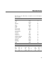


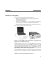

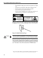
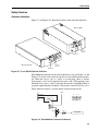
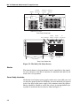
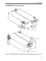
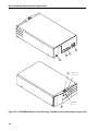
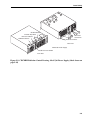
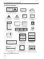
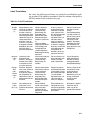


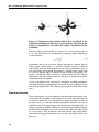
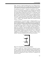
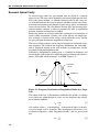
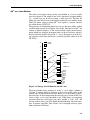
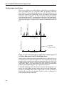
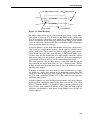
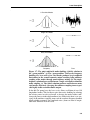
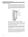
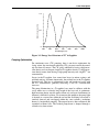
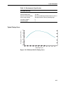
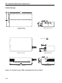
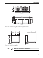

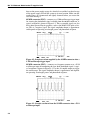
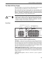
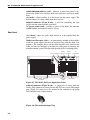
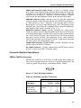
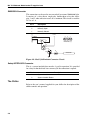
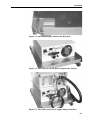
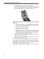
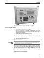
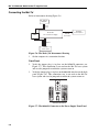
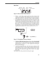
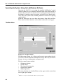
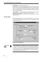
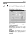
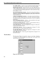
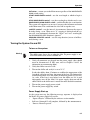
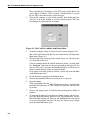

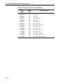


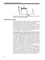
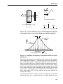
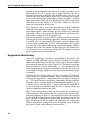
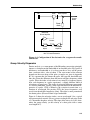
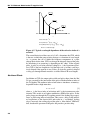
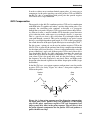

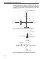
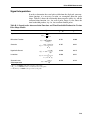
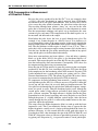
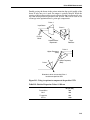
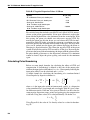
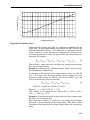

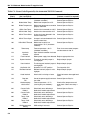


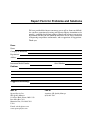


![[1 ] StorageTek SL8500](http://vs1.manualzilla.com/store/data/005684950_1-d7f31af8d49e38e9e4476c8a63e026d0-150x150.png)