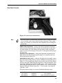
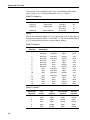
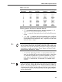
1
Stabilite 2017 Ion Laser User’s Manual Stabilite 2017 Ion Laser User’s Manual 1335 Terra Bella Road Mountain View, CA 94043 Part Number 0000-215A, Rev. D June 2001 Preface This manual contains information you need in order to safely install, operate, maintain, and service your Stabilite® 2017 ion laser system on a dayto-day basis. The system comprises three elements: the Stabilite 2017 laser head, the Model 2550 power supply, and the Model 2670 controller. The latter is a small table-top controller provided with the system for local control. If computer control is required, an optional Model 2680 computer interface is available. The “Unpacking and Inspections” section contains information on how to unpack your Stabilite 2017 system and lists the items you should have received. It also lists any options you may have purchased. Please read this short, but important, section before you begin to unpack the rest of your system. The “Introduction” contains a brief description of the Stabilite 2017 laser head, its power supply and controller. Following that section is an important chapter on laser safety. The Stabilite 2017 is a Class IV laser and, as such, emits laser radiation which can permanently damage eyes and skin. This section contains information about these hazards and offers suggestions on how to safeguard against them. It also suggests installation procedures and maintenance you must perform to keep your system in compliance with CE and CDRH regulations. To ensure your system is installed according to these regulations and to minimize the risk of injury or expensive repairs, be sure to read this chapter—then carefully follow these instructions. “Laser Description” contains a brief exposition on argon ion laser theory and is followed by a more detailed description of the Stabilite 2017 laser system. The chapter concludes with system specifications and outline drawings. The middle chapters describe the system’s controls, indicators, and connectors, then guide you through its installation and operation. A separate chapter covers the optional Model 2680 computer interface. The last part of the manual covers maintenance and service and includes a replacement parts list and a list of world-wide Spectra-Physics Service Centers you can call if you need help. Whereas the “Maintenance” section contains information you need to keep your laser clean and operational on a day-to-day basis, “Service and Repair” is intended to help you guide your Spectra-Physics field service engineer to the source of any problems. Do not attempt repairs yourself iii Stabilite 2017 Ion Laser while the unit is still under warranty; instead, report all problems to SpectraPhysics for warranty repair. This product has been tested and found to conform to “Directive 89/336/ EEC for Electromagnetic Compatibility.” Class A compliance was demonstrated for “EN 50081-2:1993 Emissions” and “EN 50082-1:1992 Immunity” as listed in the official Journal of the European Communities. It also meets the intent of “Directive 73/23/EEC for Low Voltage.” Class A compliance was demonstrated for “EN 61010-1:1993 Safety Requirements for Electrical Equipment for Measurement, Control and Laboratory use” and “EN 608251:1992 Radiation Safety for Laser Products.” Refer to the “CE Declaration of Conformity” documents in Chapter 2. Finally, if you encounter any difficulty with the content or style of this manual, please let us know. The last page is a form to aid in bringing such problems to our attention. Thank you for your purchase of Spectra-Physics instruments. iv Environmental Specifications CE Electrical Equipment Requirements For information regarding the equipment needed to provide the electrical service listed under “Service Requirements” at the end of Chapter 3, please refer to specification EN-309, “Plug, Outlet and Socket Couplers for Industrial Uses,” listed in the official Journal of the European Communities. Environmental Specifications The environmental conditions under which the laser system will function are listed below: Indoor use Altitude: up to 2000 m Temperatures: 10° C to 40° C Maximum relative humidity: 80% non-condensing for temperatures up to 31° C. Mains supply voltage: do not exceed ±10% of the nominal voltage Insulation category: II Pollution degree: 2 v Warning Conventions The following warnings are used throughout this manual to draw your attention to situations or procedures that require extra attention. They warn of hazards to your health, damage to equipment, sensitive procedures, and exceptional circumstances. All messages are set apart by a thin line above and below the text as shown here. Danger! Laser radiation is present. Laser Radiation Danger! Condition or action may present a hazard to personal safety. Danger! Condition or action may present an electrical hazard to personal safety. Warning! Condition or action may cause damage to equipment. Warning! ESD Action may cause electrostatic discharge and cause damage to equipment. Caution! Condition or action may cause poor performance or error. Note Don't Touch! Eyewear Required Text describes exceptional circumstances or makes a special reference. Do not touch. Appropriate laser safety eyewear should be worn during this operation. Refer to the manual before operating or using this device. xiii Standard Units The following units, abbreviations, and prefixes are used in this SpectraPhysics manual: Quantity Unit Abbreviation mass length time frequency force energy power electric current electric charge electric potential resistance inductance magnetic flux magnetic flux density luminous intensity temperature pressure capacitance angle kilogram meter second hertz newton joule watt ampere coulomb volt ohm henry weber tesla candela celcius pascal farad radian kg m s Hz N J W A C V Ω H Wb T cd C Pa F rad Prefixes tera 12 T deci 9 (10 ) (10-1) d nano (10-9) n giga (10 ) G centi (10 ) c pico (10 ) p mega (106) M mill (10-3) m femto (10-15) f kilo (103) k micro (10-6) µ atto (10-18) a -2 -12 xv Unpacking and Inspection Unpacking Your Laser Your Stabilite® 2017 laser was packed with great care, and its container was inspected prior to shipment—it left Spectra-Physics in good condition. Upon receiving your system, immediately inspect the outside of the shipping containers. If there is any major damage (holes in the containers, crushing, etc.), insist that a representative of the carrier be present when you unpack the contents. Carefully inspect your laser system as you unpack it. If any damage is evident, such as dents or scratches o the covers or broken knobs, etc., immediately notify the carrier and your Spectra-Physics sales representative. Keep the shipping containers. If you file a damage claim, you may need them to demonstrate that the damage occurred as a result of shipping. If you need to return the system for service at a later date, the specially designed container assures adequate protection. System Components The following components comprise the Stabilite 2017 laser system: • • • • Stabilite 2017 Laser Head Model 2550 Power Supply Model 2670 Controller Model 2680 Computer Interface (Optional) Verify all components are present. Accessory Kit Included with the laser system is this manual, a packing slip listing all the parts shipped, and an accessory kit containing the following items: • • • • • • two hoses for the water cooling system supply and return lines a water filter and two extra filter cartridges plumbing fittings to connect the water filter in the supply line plumbing fittings to connect the water filter in the supply line a tool kit containing various Allen wrenches and drivers for aligning and maintaining your laser a prism assembly with protective cap xvii Stabilite 2017 Ion Laser • • • • • • • • • xviii keys (2) for the control module 50 A fuses (3) for the power supply various small, medium-current fuses (8) for the power supply a plastic hemostat a glass solvent bottle a packet of Kodak Lens Cleaning Paper™ interlock defeat keys (2) for the laser head cover interlock a set of table clamps any optional optics assemblies that were ordered Table of Contents Preface . . . . . . . . . . . . . . . . . . . . . . . . . . . . . . . . . . . . . . . . . . . . . . . . . . . . . . . . . . . . . . iii Environmental Specifications. . . . . . . . . . . . . . . . . . . . . . . . . . . . . . . . . . . . . . . . . . . . v Warning Conventions . . . . . . . . . . . . . . . . . . . . . . . . . . . . . . . . . . . . . . . . . . . . . . . . . . xiii Standard Units . . . . . . . . . . . . . . . . . . . . . . . . . . . . . . . . . . . . . . . . . . . . . . . . . . . . . . . xv Unpacking and Inspection . . . . . . . . . . . . . . . . . . . . . . . . . . . . . . . . . . . . . . . . . . . . . . xvii Unpacking Your Laser. . . . . . . . . . . . . . . . . . . . . . . . . . . . . . . . . . . . . . . . . . . . . . . . . . . . . . . . . . . . . . xvii System Components. . . . . . . . . . . . . . . . . . . . . . . . . . . . . . . . . . . . . . . . . . . . . . . . . . . . . . . . . . . . . . . xvii Accessory Kit . . . . . . . . . . . . . . . . . . . . . . . . . . . . . . . . . . . . . . . . . . . . . . . . . . . . . . . . . . . . . . . . . . . . xvii Chapter 1: Introduction . . . . . . . . . . . . . . . . . . . . . . . . . . . . . . . . . . . . . . . . . . . . . . . . 1-1 The Stabilite 2017 System . . . . . . . . . . . . . . . . . . . . . . . . . . . . . . . . . . . . . . . . . . . . . . . . . . . . . . . . . . 1-1 The Laser Head . . . . . . . . . . . . . . . . . . . . . . . . . . . . . . . . . . . . . . . . . . . . . . . . . . . . . . . . . . . . . . . 1-1 The Model 2550 Power Supply . . . . . . . . . . . . . . . . . . . . . . . . . . . . . . . . . . . . . . . . . . . . . . . . . . . 1-2 The Model 2670 Controller . . . . . . . . . . . . . . . . . . . . . . . . . . . . . . . . . . . . . . . . . . . . . . . . . . . . . . . 1-2 Accessory Kit . . . . . . . . . . . . . . . . . . . . . . . . . . . . . . . . . . . . . . . . . . . . . . . . . . . . . . . . . . . . . . . . . 1-2 System Options. . . . . . . . . . . . . . . . . . . . . . . . . . . . . . . . . . . . . . . . . . . . . . . . . . . . . . . . . . . . . . . . . . . 1-3 The Model 2680 Computer Interface . . . . . . . . . . . . . . . . . . . . . . . . . . . . . . . . . . . . . . . . . . . . . . . 1-3 Extender Feet . . . . . . . . . . . . . . . . . . . . . . . . . . . . . . . . . . . . . . . . . . . . . . . . . . . . . . . . . . . . . . . . 1-3 Patents . . . . . . . . . . . . . . . . . . . . . . . . . . . . . . . . . . . . . . . . . . . . . . . . . . . . . . . . . . . . . . . . . . . . . . . . . 1-3 Chapter 2: Laser Safety. . . . . . . . . . . . . . . . . . . . . . . . . . . . . . . . . . . . . . . . . . . . . . . . . 2-1 Precautions for the Safe Operation of Class IV-High Power Lasers . . . . . . . . . . . . . . . . . . . . . . . . . . 2-1 Maintenance Necessary to Keep this Laser Product in Compliance with Center for Devices and Radiological Health (CDRH) Regulations . . . . . . . . . . . . . . . . . . . . . . . . 2-3 CDRH Requirements for a Custom Controller or for Operation with the Model 2180 Computer Interface . . . . . . . . . . . . . . . . . . . . . . . . . . . . . . . . . . . . . . . . . . . . 2-4 Safety Devices . . . . . . . . . . . . . . . . . . . . . . . . . . . . . . . . . . . . . . . . . . . . . . . . . . . . . . . . . . . . . . . . . . . 2-4 Emission Indicator . . . . . . . . . . . . . . . . . . . . . . . . . . . . . . . . . . . . . . . . . . . . . . . . . . . . . . . . . . . . . 2-4 Safety Interlock Keyswitch . . . . . . . . . . . . . . . . . . . . . . . . . . . . . . . . . . . . . . . . . . . . . . . . . . . . . . . 2-5 Shutter . . . . . . . . . . . . . . . . . . . . . . . . . . . . . . . . . . . . . . . . . . . . . . . . . . . . . . . . . . . . . . . . . . . . . . 2-5 Cover Safety Interlocks . . . . . . . . . . . . . . . . . . . . . . . . . . . . . . . . . . . . . . . . . . . . . . . . . . . . . . . . . 2-5 Auxiliary Safety Interlock . . . . . . . . . . . . . . . . . . . . . . . . . . . . . . . . . . . . . . . . . . . . . . . . . . . . . . . . 2-7 Operation with the Prism Cover Off . . . . . . . . . . . . . . . . . . . . . . . . . . . . . . . . . . . . . . . . . . . . . . . . . . . 2-7 CE/CDRH Radiation Control Drawings . . . . . . . . . . . . . . . . . . . . . . . . . . . . . . . . . . . . . . . . . . . . . . . . . 2-8 CE/CDRH Warning Labels . . . . . . . . . . . . . . . . . . . . . . . . . . . . . . . . . . . . . . . . . . . . . . . . . . . . . . . . . . 2-9 Label Translations . . . . . . . . . . . . . . . . . . . . . . . . . . . . . . . . . . . . . . . . . . . . . . . . . . . . . . . . . . . . . 2-10 CE Declaration of Conformity (Emissions) . . . . . . . . . . . . . . . . . . . . . . . . . . . . . . . . . . . . . . . . . . . . . . 2-11 CE Declaration of Conformity (Low Voltage) . . . . . . . . . . . . . . . . . . . . . . . . . . . . . . . . . . . . . . . . . . . . 2-12 vii Stabilite 2017 Ion Laser Sources for Additional Information . . . . . . . . . . . . . . . . . . . . . . . . . . . . . . . . . . . . . . . . . . . . . . . . . . . .2-13 Laser Safety Standards. . . . . . . . . . . . . . . . . . . . . . . . . . . . . . . . . . . . . . . . . . . . . . . . . . . . . . . . . .2-13 Equipment and Training . . . . . . . . . . . . . . . . . . . . . . . . . . . . . . . . . . . . . . . . . . . . . . . . . . . . . . . . .2-14 Chapter 3: Laser Description . . . . . . . . . . . . . . . . . . . . . . . . . . . . . . . . . . . . . . . . . . . . 3-1 Emission and Absorption of Light . . . . . . . . . . . . . . . . . . . . . . . . . . . . . . . . . . . . . . . . . . . . . . . . . . . . .3-1 Population Inversion . . . . . . . . . . . . . . . . . . . . . . . . . . . . . . . . . . . . . . . . . . . . . . . . . . . . . . . . . . . . . . .3-2 Argon as an Excitation Medium . . . . . . . . . . . . . . . . . . . . . . . . . . . . . . . . . . . . . . . . . . . . . . . . . . . . . .3-4 The Resonant Optical Cavity . . . . . . . . . . . . . . . . . . . . . . . . . . . . . . . . . . . . . . . . . . . . . . . . . . . . . . . .3-5 Power Performance Considerations . . . . . . . . . . . . . . . . . . . . . . . . . . . . . . . . . . . . . . . . . . . . . . . . . . .3-7 Stabilite 2017 System Description. . . . . . . . . . . . . . . . . . . . . . . . . . . . . . . . . . . . . . . . . . . . . . . . . . . . .3-7 The Stabilite 2017 Laser Head . . . . . . . . . . . . . . . . . . . . . . . . . . . . . . . . . . . . . . . . . . . . . . . . . . . .3-7 The Model 2550 Power Supply . . . . . . . . . . . . . . . . . . . . . . . . . . . . . . . . . . . . . . . . . . . . . . . . . . . .3-8 The Model 2670 Controller . . . . . . . . . . . . . . . . . . . . . . . . . . . . . . . . . . . . . . . . . . . . . . . . . . . . . . .3-9 Stabilite 2017 Specifications . . . . . . . . . . . . . . . . . . . . . . . . . . . . . . . . . . . . . . . . . . . . . . . . . . . . . . . . .3-9 Outline Drawings . . . . . . . . . . . . . . . . . . . . . . . . . . . . . . . . . . . . . . . . . . . . . . . . . . . . . . . . . . . . . . . . . .3-11 Chapter 4: Controls, Indicators and Connections . . . . . . . . . . . . . . . . . . . . . . . . . . . 4-1 Laser Head . . . . . . . . . . . . . . . . . . . . . . . . . . . . . . . . . . . . . . . . . . . . . . . . . . . . . . . . . . . . . . . . . . . . . .4-1 Internal Controls . . . . . . . . . . . . . . . . . . . . . . . . . . . . . . . . . . . . . . . . . . . . . . . . . . . . . . . . . . . . . . .4-1 Rear Panel Controls . . . . . . . . . . . . . . . . . . . . . . . . . . . . . . . . . . . . . . . . . . . . . . . . . . . . . . . . . . . .4-3 Indicators. . . . . . . . . . . . . . . . . . . . . . . . . . . . . . . . . . . . . . . . . . . . . . . . . . . . . . . . . . . . . . . . . . . . .4-4 Connections . . . . . . . . . . . . . . . . . . . . . . . . . . . . . . . . . . . . . . . . . . . . . . . . . . . . . . . . . . . . . . . . . .4-4 Model 2550 Power Supply. . . . . . . . . . . . . . . . . . . . . . . . . . . . . . . . . . . . . . . . . . . . . . . . . . . . . . . . . . .4-5 Controls. . . . . . . . . . . . . . . . . . . . . . . . . . . . . . . . . . . . . . . . . . . . . . . . . . . . . . . . . . . . . . . . . . . . . .4-5 Indicators. . . . . . . . . . . . . . . . . . . . . . . . . . . . . . . . . . . . . . . . . . . . . . . . . . . . . . . . . . . . . . . . . . . . .4-5 Connections . . . . . . . . . . . . . . . . . . . . . . . . . . . . . . . . . . . . . . . . . . . . . . . . . . . . . . . . . . . . . . . . . .4-5 The Model 2670 Controller . . . . . . . . . . . . . . . . . . . . . . . . . . . . . . . . . . . . . . . . . . . . . . . . . . . . . . . . . .4-6 Controls. . . . . . . . . . . . . . . . . . . . . . . . . . . . . . . . . . . . . . . . . . . . . . . . . . . . . . . . . . . . . . . . . . . . . .4-6 Indicators. . . . . . . . . . . . . . . . . . . . . . . . . . . . . . . . . . . . . . . . . . . . . . . . . . . . . . . . . . . . . . . . . . . . .4-8 Connections . . . . . . . . . . . . . . . . . . . . . . . . . . . . . . . . . . . . . . . . . . . . . . . . . . . . . . . . . . . . . . . . . .4-8 Chapter 5: Installation. . . . . . . . . . . . . . . . . . . . . . . . . . . . . . . . . . . . . . . . . . . . . . . . . . 5-1 Electrical Connections . . . . . . . . . . . . . . . . . . . . . . . . . . . . . . . . . . . . . . . . . . . . . . . . . . . . . . . . . . . . .5-1 Connecting to Electrical Service . . . . . . . . . . . . . . . . . . . . . . . . . . . . . . . . . . . . . . . . . . . . . . . . . .5-1 Connecting the Laser Head Umbilical to the Power Supply . . . . . . . . . . . . . . . . . . . . . . . . . . . . . .5-1 Control Connections . . . . . . . . . . . . . . . . . . . . . . . . . . . . . . . . . . . . . . . . . . . . . . . . . . . . . . . . . . . . . . .5-3 Installing the Model 2670 Controller . . . . . . . . . . . . . . . . . . . . . . . . . . . . . . . . . . . . . . . . . . . . . . . .5-3 Installing the Computer Interface Cable . . . . . . . . . . . . . . . . . . . . . . . . . . . . . . . . . . . . . . . . . . . . .5-3 Water Connections . . . . . . . . . . . . . . . . . . . . . . . . . . . . . . . . . . . . . . . . . . . . . . . . . . . . . . . . . . . . . . . .5-5 Cooling Water Requirements . . . . . . . . . . . . . . . . . . . . . . . . . . . . . . . . . . . . . . . . . . . . . . . . . . . . .5-5 Closed-loop Cooling Systems . . . . . . . . . . . . . . . . . . . . . . . . . . . . . . . . . . . . . . . . . . . . . . . . . . . .5-6 Laser Head Inspection . . . . . . . . . . . . . . . . . . . . . . . . . . . . . . . . . . . . . . . . . . . . . . . . . . . . . . . . . . . . .5-6 Adjusting the Height of the Laser Head . . . . . . . . . . . . . . . . . . . . . . . . . . . . . . . . . . . . . . . . . . . . . . . .5-6 Preoperation Water Leak Tests . . . . . . . . . . . . . . . . . . . . . . . . . . . . . . . . . . . . . . . . . . . . . . . . . . . . . .5-6 Chapter 6: Operation . . . . . . . . . . . . . . . . . . . . . . . . . . . . . . . . . . . . . . . . . . . . . . . . . . 6-1 Starting the Laser . . . . . . . . . . . . . . . . . . . . . . . . . . . . . . . . . . . . . . . . . . . . . . . . . . . . . . . . . . . . . . . . .6-1 Adjusting for Maximum Output Power . . . . . . . . . . . . . . . . . . . . . . . . . . . . . . . . . . . . . . . . . . . . . . . . .6-2 Turning Off the Laser. . . . . . . . . . . . . . . . . . . . . . . . . . . . . . . . . . . . . . . . . . . . . . . . . . . . . . . . . . . . . . .6-2 Automatic Fill Circuit . . . . . . . . . . . . . . . . . . . . . . . . . . . . . . . . . . . . . . . . . . . . . . . . . . . . . . . . . . . . . . .6-3 Removing and Installing Mirror Holders . . . . . . . . . . . . . . . . . . . . . . . . . . . . . . . . . . . . . . . . . . . . .6-3 Bayonet-style Mirror Holders . . . . . . . . . . . . . . . . . . . . . . . . . . . . . . . . . . . . . . . . . . . . . . . . . . . . .6-3 viii Table of Contents Removing/Replacing the Mirrors . . . . . . . . . . . . . . . . . . . . . . . . . . . . . . . . . . . . . . . . . . . . . . . . . . 6-3 Interchanging the Broadband Mirror Holder and Prism Assembly . . . . . . . . . . . . . . . . . . . . . . . . . . . . 6-5 Wavelength Selection Using a Prism . . . . . . . . . . . . . . . . . . . . . . . . . . . . . . . . . . . . . . . . . . . . . . . . . . 6-5 Setting the Aperture for TEM00 Output . . . . . . . . . . . . . . . . . . . . . . . . . . . . . . . . . . . . . . . . . . . . . . . . 6-6 Viewing the Mode . . . . . . . . . . . . . . . . . . . . . . . . . . . . . . . . . . . . . . . . . . . . . . . . . . . . . . . . . . . . . 6-7 Chapter 7: Model 2680 Computer Interface. . . . . . . . . . . . . . . . . . . . . . . . . . . . . . . . . 7-1 Description . . . . . . . . . . . . . . . . . . . . . . . . . . . . . . . . . . . . . . . . . . . . . . . . . . . . . . . . . . . . . . . . . . . . . . 7-2 Computer Control Functions . . . . . . . . . . . . . . . . . . . . . . . . . . . . . . . . . . . . . . . . . . . . . . . . . . . . . . . . 7-2 Installation . . . . . . . . . . . . . . . . . . . . . . . . . . . . . . . . . . . . . . . . . . . . . . . . . . . . . . . . . . . . . . . . . . . . . . 7-2 To Install the CI: . . . . . . . . . . . . . . . . . . . . . . . . . . . . . . . . . . . . . . . . . . . . . . . . . . . . . . . . . . . . . . 7-2 Commands . . . . . . . . . . . . . . . . . . . . . . . . . . . . . . . . . . . . . . . . . . . . . . . . . . . . . . . . . . . . . . . . . . . . . . 7-3 Status Commands . . . . . . . . . . . . . . . . . . . . . . . . . . . . . . . . . . . . . . . . . . . . . . . . . . . . . . . . . . . . . 7-3 Control Commands . . . . . . . . . . . . . . . . . . . . . . . . . . . . . . . . . . . . . . . . . . . . . . . . . . . . . . . . . . . . 7-6 Power Supply “On” Default Condition . . . . . . . . . . . . . . . . . . . . . . . . . . . . . . . . . . . . . . . . . . . . . . . . . 7-7 To use the CI: . . . . . . . . . . . . . . . . . . . . . . . . . . . . . . . . . . . . . . . . . . . . . . . . . . . . . . . . . . . . . . . . 7-7 Initializing the Interface . . . . . . . . . . . . . . . . . . . . . . . . . . . . . . . . . . . . . . . . . . . . . . . . . . . . . . . . . 7-7 IEEE-488 Interface . . . . . . . . . . . . . . . . . . . . . . . . . . . . . . . . . . . . . . . . . . . . . . . . . . . . . . . . . . . . . . . . 7-8 Operation . . . . . . . . . . . . . . . . . . . . . . . . . . . . . . . . . . . . . . . . . . . . . . . . . . . . . . . . . . . . . . . . . . . . 7-8 Remote Reset . . . . . . . . . . . . . . . . . . . . . . . . . . . . . . . . . . . . . . . . . . . . . . . . . . . . . . . . . . . . . . . . 7-8 Serial Poll Status Byte . . . . . . . . . . . . . . . . . . . . . . . . . . . . . . . . . . . . . . . . . . . . . . . . . . . . . . . . . . 7-8 SW2 DIP Switch Setting . . . . . . . . . . . . . . . . . . . . . . . . . . . . . . . . . . . . . . . . . . . . . . . . . . . . . . . . 7-10 RS-232-C Interface . . . . . . . . . . . . . . . . . . . . . . . . . . . . . . . . . . . . . . . . . . . . . . . . . . . . . . . . . . . . . . . 7-11 Operation . . . . . . . . . . . . . . . . . . . . . . . . . . . . . . . . . . . . . . . . . . . . . . . . . . . . . . . . . . . . . . . . . . . . 7-11 Data Transfer and Handshaking . . . . . . . . . . . . . . . . . . . . . . . . . . . . . . . . . . . . . . . . . . . . . . . . . . 7-12 SW1 DIP Switch Setting . . . . . . . . . . . . . . . . . . . . . . . . . . . . . . . . . . . . . . . . . . . . . . . . . . . . . . . . 7-12 SW3 DIP Switch Setting . . . . . . . . . . . . . . . . . . . . . . . . . . . . . . . . . . . . . . . . . . . . . . . . . . . . . . . . 7-13 Message Formats . . . . . . . . . . . . . . . . . . . . . . . . . . . . . . . . . . . . . . . . . . . . . . . . . . . . . . . . . . . . . . . . 7-13 Command Format . . . . . . . . . . . . . . . . . . . . . . . . . . . . . . . . . . . . . . . . . . . . . . . . . . . . . . . . . . . . . 7-13 Response Format . . . . . . . . . . . . . . . . . . . . . . . . . . . . . . . . . . . . . . . . . . . . . . . . . . . . . . . . . . . . . 7-14 Programming Example . . . . . . . . . . . . . . . . . . . . . . . . . . . . . . . . . . . . . . . . . . . . . . . . . . . . . . . . . . . . . 7-15 Chapter 8: Maintenance . . . . . . . . . . . . . . . . . . . . . . . . . . . . . . . . . . . . . . . . . . . . . . . . 8-1 Notes on the Cleaning of Laser Optics . . . . . . . . . . . . . . . . . . . . . . . . . . . . . . . . . . . . . . . . . . . . . . . . 8-1 Cleaning Optics . . . . . . . . . . . . . . . . . . . . . . . . . . . . . . . . . . . . . . . . . . . . . . . . . . . . . . . . . . . . . . . . . . 8-2 Equipment Required . . . . . . . . . . . . . . . . . . . . . . . . . . . . . . . . . . . . . . . . . . . . . . . . . . . . . . . . . . . 8-2 Cleaning Solutions Required . . . . . . . . . . . . . . . . . . . . . . . . . . . . . . . . . . . . . . . . . . . . . . . . . . . . . 8-2 Cleaning Mirrors . . . . . . . . . . . . . . . . . . . . . . . . . . . . . . . . . . . . . . . . . . . . . . . . . . . . . . . . . . . . . . 8-3 Cleaning the Prism Assembly . . . . . . . . . . . . . . . . . . . . . . . . . . . . . . . . . . . . . . . . . . . . . . . . . . . . 8-4 Cleaning Plasma Tube Windows . . . . . . . . . . . . . . . . . . . . . . . . . . . . . . . . . . . . . . . . . . . . . . . . . . 8-6 Replacing the Water Filter . . . . . . . . . . . . . . . . . . . . . . . . . . . . . . . . . . . . . . . . . . . . . . . . . . . . . . . . . . 8-8 Cleaning the Power Supply Water Filter . . . . . . . . . . . . . . . . . . . . . . . . . . . . . . . . . . . . . . . . . . . . . . . 8-9 Chapter 9: Service and Repair . . . . . . . . . . . . . . . . . . . . . . . . . . . . . . . . . . . . . . . . . . . 9-1 Vertical Search Alignment Procedure . . . . . . . . . . . . . . . . . . . . . . . . . . . . . . . . . . . . . . . . . . . . . . . . . 9-1 Electronic Repair . . . . . . . . . . . . . . . . . . . . . . . . . . . . . . . . . . . . . . . . . . . . . . . . . . . . . . . . . . . . . . . . . 9-1 Replacement Parts . . . . . . . . . . . . . . . . . . . . . . . . . . . . . . . . . . . . . . . . . . . . . . . . . . . . . . . . . . . . . . . . 9-2 Troubleshooting . . . . . . . . . . . . . . . . . . . . . . . . . . . . . . . . . . . . . . . . . . . . . . . . . . . . . . . . . . . . . . . . . . 9-2 Chapter 10: Customer Service . . . . . . . . . . . . . . . . . . . . . . . . . . . . . . . . . . . . . . . . . . . 10-1 Warranty . . . . . . . . . . . . . . . . . . . . . . . . . . . . . . . . . . . . . . . . . . . . . . . . . . . . . . . . . . . . . . . . . . . . . . . . 10-1 Return of the Instrument for Repair . . . . . . . . . . . . . . . . . . . . . . . . . . . . . . . . . . . . . . . . . . . . . . . . . . . 10-2 Service Centers . . . . . . . . . . . . . . . . . . . . . . . . . . . . . . . . . . . . . . . . . . . . . . . . . . . . . . . . . . . . . . . . . . 10-3 ix Stabilite 2017 Ion Laser List of Figures Figure 1-1: The Stabilite 2017 Laser System . . . . . . . . . . . . . . . . . . . . . . . . . . . . . . . . . . . . . . . . . . . .1-1 Figure 2-1: These CE and CDRH standard safety warning labels would be appropriate for use as entry warning signs (EN 60825-1, ANSI 4.3.10.1). . . . . . . . . . . . . . . . . . . . . . . . . . . . .2-2 Figure 2-2: Folded Metal Beam Target . . . . . . . . . . . . . . . . . . . . . . . . . . . . . . . . . . . . . . . . . . . . . . . . .2-2 Figure 2-3: Laser Head Safety Interlock Key, Intracavity Shutter, and Emission Indicator . . . . . . . . .2-4 Figure 2-4: Model 2670 Controller Emission Indicator . . . . . . . . . . . . . . . . . . . . . . . . . . . . . . . . . . . . .2-5 Figure 2-5: Power Supply Safety Interlock Switch . . . . . . . . . . . . . . . . . . . . . . . . . . . . . . . . . . . . . . . .2-6 Figure 2-6: The AUX INTLK connector . . . . . . . . . . . . . . . . . . . . . . . . . . . . . . . . . . . . . . . . . . . . . . . . .2-7 Figure 2-7: A portion of the intracavity beam is reflected upward from each face of the prism. . . . . . .2-7 Figure 2-8: CE/CDRH Radiation Control Drawing . . . . . . . . . . . . . . . . . . . . . . . . . . . . . . . . . . . . . . . .2-8 Figure 2-9: CE/CDRH Warning Labels . . . . . . . . . . . . . . . . . . . . . . . . . . . . . . . . . . . . . . . . . . . . . . . . .2-9 Figure 2-8: Electrical Safety Labels . . . . . . . . . . . . . . . . . . . . . . . . . . . . . . . . . . . . . . . . . . . . . . . . . . .2-10 Figure 3-1: Electrons occupy distinct orbitals that are defined by the probability of finding an electron at a given position, the shape of the orbital being determined by the radial and angular dependence of the probability. . . . . . . . . . . . . . . . . . . . . . . . . . . . . . . . . . . . . . . . . . . . . .3-2 Figure 3-2: A typical four-level laser transition scheme (a) compared to that of visible argon (b). One electron collision ionizes neutral argon, and a second pumps the ion to an excited state. . . .3-3 Figure 3-3: Energy Levels of the 4p-4s Argon Ion Laser Transitions . . . . . . . . . . . . . . . . . . . . . . . . . .3-4 Figure 3-4: Frequency Distribution of Longitudinal Modes for a Single Line . . . . . . . . . . . . . . . . . . . .3-6 Figure 3-5: Outline Drawings. . . . . . . . . . . . . . . . . . . . . . . . . . . . . . . . . . . . . . . . . . . . . . . . . . . . . . . . .3-11 Figure 4-1: Laser Head Interior—Output End . . . . . . . . . . . . . . . . . . . . . . . . . . . . . . . . . . . . . . . . . . .4-1 Figure 4-2: Laser Head Control Panel . . . . . . . . . . . . . . . . . . . . . . . . . . . . . . . . . . . . . . . . . . . . . . . . .4-3 Figure 4-3: The Stabilite 2017 Prism Assembly . . . . . . . . . . . . . . . . . . . . . . . . . . . . . . . . . . . . . . . . . .4-4 Figure 4-4: Front Panel of the Model 2550 Power Supply. . . . . . . . . . . . . . . . . . . . . . . . . . . . . . . . . . .4-5 Figure 4-5: The Model 2670 Controller . . . . . . . . . . . . . . . . . . . . . . . . . . . . . . . . . . . . . . . . . . . . . . . . .4-7 Figure 4-6: Model 2670 Controller Rear Panel . . . . . . . . . . . . . . . . . . . . . . . . . . . . . . . . . . . . . . . . . . .4-9 Figure 5-1: Model 2550 Power Supply with the Cover Removed . . . . . . . . . . . . . . . . . . . . . . . . . . . . .5-2 Figure 5-2: Connecting the Cooling Water Loop . . . . . . . . . . . . . . . . . . . . . . . . . . . . . . . . . . . . . . . . .5-6 Figure 6-1: The laser head showing the output coupler holder . . . . . . . . . . . . . . . . . . . . . . . . . . . . . . .6-3 Figure 6-2: Only one line of the cavity beam spread by the prism is at the proper angle to return along the beam path and become amplified. . . . . . . . . . . . . . . . . . . . . . . . . . . . . . . . . . . . .6-6 Figure 6-3: Transverse Modes . . . . . . . . . . . . . . . . . . . . . . . . . . . . . . . . . . . . . . . . . . . . . . . . . . . . . . .6-7 Figure 7-1: Model 2550 Power Supply Connector Panel . . . . . . . . . . . . . . . . . . . . . . . . . . . . . . . . . . .7-1 Figure 7-2: Diagram of the serial poll status byte indicating the function of each bit. . . . . . . . . . . . . . .7-8 Figure 7-3: Model 2680 Computer Interface . . . . . . . . . . . . . . . . . . . . . . . . . . . . . . . . . . . . . . . . . . . . .7-10 Figure 8-1: Cleaning a Mirror Surface . . . . . . . . . . . . . . . . . . . . . . . . . . . . . . . . . . . . . . . . . . . . . . . . .8-3 Figure 8-2: Prism Assembly . . . . . . . . . . . . . . . . . . . . . . . . . . . . . . . . . . . . . . . . . . . . . . . . . . . . . . . . .8-4 Figure 8-3: Lens Tissue Folded for Cleaning . . . . . . . . . . . . . . . . . . . . . . . . . . . . . . . . . . . . . . . . . . . .8-5 Figure 8-4: A portion of the intracavity beam is reflected upward from each face of the prism. . . . . . .8-6 Figure 9-1:Troubleshooting Flowchart . . . . . . . . . . . . . . . . . . . . . . . . . . . . . . . . . . . . . . . . . . . . . . . . .9-3 List of Tables Table 2-1: Label Translations . . . . . . . . . . . . . . . . . . . . . . . . . . . . . . . . . . . . . . . . . . . . . . . . . . . . . . . .2-10 Table 3-1: Argon Output Power. . . . . . . . . . . . . . . . . . . . . . . . . . . . . . . . . . . . . . . . . . . . . . . . . . . . . . .3-9 Table 3-2: Krypton Output Power . . . . . . . . . . . . . . . . . . . . . . . . . . . . . . . . . . . . . . . . . . . . . . . . . . . . .3-9 Table 3-3: Optical Characteristics . . . . . . . . . . . . . . . . . . . . . . . . . . . . . . . . . . . . . . . . . . . . . . . . . . . . .3-10 Table 3-4: Stabilite 2017 Mechanical Specifications . . . . . . . . . . . . . . . . . . . . . . . . . . . . . . . . . . . . . . .3-10 Table 4-1: Aperture Diameters . . . . . . . . . . . . . . . . . . . . . . . . . . . . . . . . . . . . . . . . . . . . . . . . . . . . . . .4-2 Table 4-2: Model 2670 Controller Interface Pin Assignments . . . . . . . . . . . . . . . . . . . . . . . . . . . . . . . .4-10 Table 5-1: Stabilite 2017 Cooling Water Requirements . . . . . . . . . . . . . . . . . . . . . . . . . . . . . . . . . . . .5-5 Table 6-1: Aperture Diameters . . . . . . . . . . . . . . . . . . . . . . . . . . . . . . . . . . . . . . . . . . . . . . . . . . . . . . .6-6 Table 7-1: SAMPLE a . . . . . . . . . . . . . . . . . . . . . . . . . . . . . . . . . . . . . . . . . . . . . . . . . . . . . . . . . . . . . .7-4 x Table of Contents Table 7-2: READ 4 . . . . . . . . . . . . . . . . . . . . . . . . . . . . . . . . . . . . . . . . . . . . . . . . . . . . . . . . . . . . . . . . 7-4 Table 7-3: READ 5 . . . . . . . . . . . . . . . . . . . . . . . . . . . . . . . . . . . . . . . . . . . . . . . . . . . . . . . . . . . . . . . . 7-4 Table 7-4: WRITE p, n . . . . . . . . . . . . . . . . . . . . . . . . . . . . . . . . . . . . . . . . . . . . . . . . . . . . . . . . . . . . . 7-6 Table 7-5: SW2 DIP switch settings for Selecting Device Address . . . . . . . . . . . . . . . . . . . . . . . . . . . 7-10 Table 7-6: Standard RS-232-C Interconnections . . . . . . . . . . . . . . . . . . . . . . . . . . . . . . . . . . . . . . . . . 7-11 Table 7-7: SW1 Baud Rate Settings . . . . . . . . . . . . . . . . . . . . . . . . . . . . . . . . . . . . . . . . . . . . . . . . . . . 7-12 Table 7-8: SW1 Mode Select Settings . . . . . . . . . . . . . . . . . . . . . . . . . . . . . . . . . . . . . . . . . . . . . . . . . 7-12 Table 7-9: CI Command Abbreviations . . . . . . . . . . . . . . . . . . . . . . . . . . . . . . . . . . . . . . . . . . . . . . . . 7-14 Table 9-1: Replacement Parts . . . . . . . . . . . . . . . . . . . . . . . . . . . . . . . . . . . . . . . . . . . . . . . . . . . . . . . 9-2 Notes Report Form for Problems and Solutions xi Stabilite 2017 Ion Laser xii Chapter 1 Introduction The Stabilite 2017 System The Stabilite® 2017 general-purpose ion laser comprises three main elements: • Stabilite 2017 laser head • Model 2550 power supply • Model 2670 controller Optional accessories for the Stabilite 2017 include: • Model 2680 computer interface • Extender feet (PN 0440-5710) Figure 1-1: The Stabilite 2017 Laser System The Laser Head The laser head is fully described in Chapter 3. It can provide several wavelengths of laser output, depending on the plasma gas used. An Argon system can provide these single-line wavelengths: 514.5 nm 488.0 nm 465.8 nm 501.7 nm 476.5 nm 457.9 nm 496.5 nm 472.7 nm 454.5 nm and these multiline wavelengths: 333.6–363.8 nm 457.9–514.5 nm A Krypton system can provide these single line wavelengths: 676.4 nm 647.1 nm and these multiline wavelengths: 647.1–676.4 nm 1-1 Stabilite 2017 Ion Laser The specifications table at the end of Chapter 3 lists the specified output power for each of these wavelengths along with the laser model required to produce them. Both the Stabilite 2017 laser head and power supply are water-cooled. Specifications for water quality and pressure are listed in Chapter 4. If your local water does not meet these quality standards or flow rate, a closed-loop system, such as the Model 315A, might be required. If this is the case, call your Spectra-Physics service representative to inquire. Caution! The Model 2550 Power Supply The Model 2550 power supply provides ample low-noise current to create a plasma discharge in the laser plasma tube. It also provides a control interface to which the Model 2670 controller or a user-supplied controller is connected. To control the laser system remotely by computer, the optional Model 2680 computer interface (see “System Options” below) is used. This option provides both RS-232 serial or IEEE-488 parallel interface connections. The power supply requires a 208 Vac ±10%, 3-phase, 42 A electrical source, and its high-power regulating devices are water cooled. Refer to the cautionary statement above. The Model 2670 Controller The easy to use Model 2670 controller, included with the system, provides all the controls necessary for local laser operation. Using this device, you can turn on and off the system, select power or current mode, set the output power or plasma current and monitor the output via the large meter. Status lamps provide information regarding the interlock system, fill circuit and laser emission. A long 3 m (10 ft) cord that attaches to the power supply allows you to place the controller anywhere on a standard table so that it is always conveniently in reach. Accessory Kit Included with the laser system is an accessory kit that contains the following items: • • • • • • • • 1-2 two hoses for the water cooling system supply and return lines a water filter and two extra filter cartridges plumbing fittings to connect the water filter in the supply line a tool kit containing various Allen wrenches and drivers for aligning and maintaining your laser a prism assembly with protective cap keys (2) for the controller 50 A fuses (3) for the power supply various small, medium-current fuses (8) for the power supply Introducation • • • • • • a plastic hemostat a glass solvent bottle a packet of Kodak Lens Cleaning Paper™ interlock defeat keys (2) for the laser head cover interlock a set of table clamps any optional optics assemblies or system options (see below) that were ordered System Options The Model 2680 Computer Interface The optional Model 2680 computer interface provides standard digital data links through RS-232-C and IEEE-488 interfaces, thus allowing a computer or terminal to operate the system. Chapter 7 provides a complete list of the commands and queries used by the Model 2680 and describes their use. Also included in that chapter is a sample program written in BASIC. Extender Feet Extender feet are used to raise the Stabilite 2017 to the appropriate height to pump a Model 375B cw dye laser. Patents The Stabilite 2017 laser system is manufactured or marketed under one or more of the following U.S.A. patents: 4,063,808 4,613,972 4,668,906 4,685,109 4,706,256 4,719,638 4,872,104 4,982,708 4,203,080 4,615,034 4,677,640 4,685,110 4,715,039 4,809,293 4,947,102 4,988,942 4,442,524 4,649,547 4,683,575 4,719,404 4,816,741 4,974,228 5,002,371 5,047,609 1-3 Stabilite 2017 Ion Laser 1-4 Chapter 2 Laser Safety The Spectra-Physics Stabilite® 2017 is a Class IV—High Power Laser whose beam is, by definition, a safety and fire hazard. Take pre cautions to prevent accidental exposure to both direct and reflected beams. Diffuse as well as specular beam reflections can cause severe eye or skin damage. Danger! Laser Radiation Precautions for the Safe Operation of Class IV-High Power Lasers • • • • • • • • • • • • • Wear protective eyewear at all times; selection depends on the wavelength and intensity of the radiation, the conditions of use, and the visual function required. Protective eyewear is available from vendors listed in the Laser Focus World, Lasers and Optronics, and Photonics Spectra buyer's guides. Consult the ANSI, ACGIH, or OSHA standards listed at the end of this section for guidance. Keep the protective cover on the laser head at all times. Avoid looking at the output beam; even diffuse reflections are hazardous. Operate the laser at the lowest beam intensity possible, given the requirements of the application. Expand the beam whenever possible to reduce beam intensity. Avoid intercepting the output beam or its reflection with any part of the body. Establish a controlled-access area for laser operation. Limit access to those trained in laser safety principles. Maintain a high ambient light level in the laser operation area so the eye's pupil remains constricted, reducing the possibility of damage. Post prominent warning signs near the laser operation area (Figure 2-1). Set up experiments so the laser beam is either above or below eye level. Provide enclosures for beam paths whenever possible. Set up shields to prevent unnecessary specular reflections. Set up an energy absorbing target to capture the laser beam, pre venting unnecessary reflections or scattering (Figure 2-2). 2-1 Stabilite 2017 Ion Laser VISIBLE AND/OR INVISIBLE* LASER RADIATION DANGER AVOID EYE OR SKIN EXPOSURE TO DIRECT OR SCATTERED RADIATION CLASS 4 LASER PRODUCT ARGON/KRYPTON MAXIMUM OUTPUT 20 W *SEE MANUAL 0451-8140 VISIBLE & INVISIBLE* LASER RADIATION RAYONNEMENT LASER VISIBLE* ET INVISIBLE AVOID EYE OR SKIN EXPOSURE TO DIRECT OR SCATTERED RADIATION EXPOSITION DANGEREUSE DE L'OEIL OU DE LA PEAU AU RAYONNEMENT DIRECT OU DIFFUS. LASER DE CLASSE 4 ARGON/KRYPTON PUISSANCE MAXIMUM 20 W *VOIR MANUEL D'UTILISATION ARGON/KRYPTON/ *SEE MANUAL 20 W CLASS IV LASER PRODUCT Figure 2-1: These CE and CDRH standard safety warning labels would be appropriate for use as entry warning signs (EN 60825-1, ANSI 4.3.10.1). Figure 2-2: Folded Metal Beam Target Caution! Danger! Laser Radiation Use of controls or adjustments, or performance of procedures other than those specified herein may result in hazardous radiation exposure. Follow the instructions contained in this manual for safe operation of your laser. At all times during operation, maintenance, or service of your laser, avoid unnecessary exposure to laser or collateral radiation* that exceeds the accessible emission limits listed in “Performance Standards for Laser Products,” United States Code of Federal Regulations, 21CFR1040 10(d). * Any electronic product radiation, except laser radiation, emitted by a laser product as a result of, or necessary for, the operation of a laser incorporated into that product. 2-2 Laser Safety Maintenance Necessary to Keep this Laser Product in Compliance with Center for Devices and Radiological Health (CDRH) Regulations This laser product complies with Title 21 of the United States Code of Federal Regulations, Chapter 1, Subchapter J, Parts 1040.10 and 1040.11, as applicable. To maintain compliance with these regulations, once a year or whenever the product has been subjected to adverse environmental conditions (e.g., fire, flood, mechanical shock, spilled solvent), check to see that all features of the product identified on the radiation control drawing (Figure 2-8) function properly. Also, make sure that all the safety warning labels shown in Figure 2-9 remain firmly attached. 1. Verify that removing the auxiliary interlock plug on the power supply prevents laser operation. 2. Verify that the laser will only operate with the key switch in the ON position, and that the key can only be removed when the switch is in the OFF position. 3. Verify that the emission indicator provides a visible signal when the laser emits accessible laser radiation that exceeds the accessible emission limits for Class I.1 4. Verify that a time delay exists between the turn-on of the emission indicator and the starting of the laser; it must give enough warning to allow action to avoid exposure to laser radiation. 5. Verify that the beam attenuator actually blocks exposure to laser radiation. 6. Verify that removing the laser head cover shuts off the laser. 7. Verify that, when the cover interlock is defeated, the defeat mechanism is clearly visible and prevents installation of the cover until disengaged. 1 0.39 mW for continuous-wave operation where output is limited to the 400 to 1400 nm range. 2-3 Stabilite 2017 Ion Laser CDRH Requirements for a Custom Controller or for Operation with the Model 2680 Computer Interface The Stabilite 2017 laser head and the Model 2550 power supply comply with all CDRH safety standards when operated with a Model 2670 control module. However, when the laser and power supply are operated without the Model 2670 controller, through either the REMOTE interface or the Model 2680 computer interface, you must provide the following in order to satisfy CDRH regulations: Key Switch—a means of limiting laser access. It can be a real key lock, a removable computer disk, a password that limits access to computer control software, or similar implement. The laser must be capable of operation only when the key is present and in the on position. Emission Indicator—indicates that laser energy is, or can be, accessible. It can be a “power-on” lamp, computer display or similar indicator on the control equipment. It need not be marked as an emission indicator so long as its function is obvious. Its presence is required on any control panel that affects laser output. Remote Interlock Connector—prevents laser operation when removed. A jumper between pins 23 and 24 on the REMOTE connector is required for operation. The jumper connected to the auxiliary interlock (AUX INTLK) connector on the Model 2670 controller provides this function. Safety Devices Emission Indicator Figure 2-3 shows the location of the emission indicator on the laser head (white). Figure 2-4 shows the location of the emission indicator on the Model 2670 controller (red). These indicators turn on immediately when emission is requested and remain on to indicate emission is present or imminent. A CDRH safety delay is imposed between initial indicator turn on and actual laser emission to allow personnel to take appropriate evasive action (to move out of the way or turn the laser off) if necessary. Intracavity Shutter Emmission Indicator Safety Interlock Key Repository for Interlock Key when not in use Figure 2-3: Laser Head Safety Interlock Key, Intracavity Shutter, and Emission Indicator 2-4 Laser Safety Safety Interlock Keyswitch Emission Indicator Figure 2-4: Model 2670 Controller Emission Indicator Safety Interlock Keyswitch The safety interlock keyswitch on the Model 2670 controller (Figure 2-4) limits laser access to only those personnel with permission and who have had adequate laser safety training. Without the key, the laser cannot be turned on. Nor can the laser be left on and the key removed. The key can only be removed in the “off” position. Always remove the key when done operating the laser. Shutter The laser head shutter is a lever-actuated mechanical device (Figure 2-3) that, when closed, interrupts the intracavity beam and prevents the laser from lasing. “O” is the open position, “Ø” is the closed position. Cover Safety Interlocks The Stabilite 2017 has safety interlocks for both the laser head cover and power supply cover. Removing either of these covers causes the main power contactor to open, which shuts off electrical power to the laser. The covers must be in place or their interlocks defeated before the laser will operate. Danger! Both the laser head and power supply contain electrical circuits operating at lethal voltage and current levels. Be extremely careful whenever the cover is removed from either unit. Avoid contact with the high voltage terminals and components inside each unit. Laser Head Danger! Laser Radiation While the laser head cover is removed, be extremely careful to avoid exposure to laser or collateral radiation. 2-5 Stabilite 2017 Ion Laser Installing the key in the laser head safety interlock switch allows you to operate the laser with its cover removed (Figure 2-3). It also prevents the cover from being replaced while the laser is running (an electrical hazard) by providing mechanical interference with the cover. Shut off the laser first, then remove the interlock key, store the key in the clamp on the side of the interlock switch and replace the cover. Power Supply The power supply cover interlock switch (Figure 2-5) is a 3-position, plunger-actuated switch. When the cover is in place, the plunger is pressed down into its momentary, normally-closed position and the power supply is permitted to operate. When the cover is removed, a spring inside the switch moves it to its normally-open center position where it opens the interlock circuit and turns off the laser or prevents it from turning on. Pulling up the plunger defeats the switch (it closes) and allows you to operate the laser with the power supply cover removed. When you replace the cover, the plunger moves the switch back through its normally-open position where it again turns off the laser. It is best to shut off the laser and power down the high-voltage components in the power supply before replacing the cover. Danger! Be extremely careful to avoid contact with high voltage if operating the laser with the cover off. Safety Interlock Switch (shown pulled up in defeat position) Figure 2-5: Power Supply Safety Interlock Switch 2-6 Laser Safety Auxiliary Safety Interlock The 2-pin Molex AUX INTLK interlock connector on the back of the Model 2670 controller (Figure 2-6) is meant to be wired to a CDRH external interlock switch. Remove the jumper plug supplied and either rewire it or use a similar connector to wire to a perimeter safety switch. Then attach the switch to an access door or to other auxiliary safety equipment. Wire the switch as “normally closed” so that when the door or safety device opens and the switch opens, the power supply will immediately turn off the laser as a safety precaution to prevent unaware personnel from getting hurt. MONITOR REMOTE AUX INTLK MODULATION Spectra-Physics MODEL NUMBER 2670 SERIAL NUMBER 3862 MADE IN U.S.A. 404-471 Figure 2-6: The AUX INTLK connector (shown in the lower left corner). Operation with the Prism Cover Off Danger! Laser Radiation If the prism assembly is installed with its cover off, a portion of the intracavity beam is reflected upward from each face of the prism (Figure 27). Avoid eye contact with these beams. Intracavity Beam Prism Reflected Beams Mirror Figure 2-7: A portion of the intracavity beam is reflected upward from each face of the prism. 2-7 Stabilite 2017 Ion Laser CE/CDRH Radiation Control Drawings 23 22 8 9 6 Stabilite® 2017 Laser Head 10 23 1 22 9 10 26 12 11 5 7 e ilit 201 26 10 b Sta 4 16 17 14 25 5 24 3 2 8 13 7 1 15 Model 2550 Power Supply 19 18 21 20 Model 2670 Controller 24 HORIZ Water Out Water In VERT VISIBLE AND INVISIBLE* LASER RADIATION IS EMITTED FROM THIS APERTURE 3 AVOID OID EXPOSURE Output End View 1 2 3 4 5 6 7 8 9 10 11 12 13 Certification & Identification Label Danger Class IV Warning Logo Label Aperture Label Danger Interlocked Housing Label Danger When Open Label Danger Cavity Seal Label Aperture, Shutter, Beam Diameter Label Ground Label Lightning Bolt Label, Large European High Voltage Label Head Cover Interlock Switch Emission Indicator Light (Laser Head) Mechanical Shutter Rear Panel View 14 15 16 17 18 19 20 21 22 23 24 25 26 Top Cover (Protective Housing) Configuration Label Patent Label Remote Connector (Includes Interlock) Interlock Shorting Cap Serial Label, Remote Control Key Switch (On/Off) Emission Indicator Light (Remote Control) Caution High Voltage Label Lightning Bolt Label, Small CE Aperture Label CE Certification Label CE Caution Label Figure 2-8: CE/CDRH Radiation Control Drawing (refer to the warning labels on next page) 2-8 Laser Safety CE/CDRH Warning Labels SPECTRA-PHYSICS LASERS P. O. BOX 7013 MT. VIEW, CALIFORNIA 94023-7013 MANUFACTURED: VISIBLE AND/OR INVISIBLE* LASER RADIATION YR MONTH AVOID EYE OR SKIN EXPOSURE TO DIRECT OR SCATTERED RADIATION S/N MODEL THIS LASER PRODUCT COMPLIES WITH 21 CFR 1040 AS APPLICABLE VISIBLE VISIBLE AND AND INVISIBLE* INVISIBLE* LASER LASER RADIATION RADIATION IS IS EMITTED EMITTED FROM FROM THIS THIS APERTURE APERTURE CLASS 4 LASER PRODUCT ARGON/KRYPTON MAXIMUM OUTPUT 20 W MADE IN U.S.A. *SEE *SEE MANUAL MANUAL *SEE MANUAL 0451-8140 Aperture Label (3) CE Danger Class IV Warning Label (2) Certification and Identification Label (1) VISIBLE INVISIBLE DANGER DANGER LASER RADIATION AND/OR LASER RADIATION IS EMITTED VISIBLE AND INVISIBLE* LASER RADIATION WHEN OPEN-AVOID SKIN OR EYE EXPOSURE TO DIRECT OR SCATTERED RADIATION V I S I B L E A N D I N V I S I B L E LASER RADIATION WHEN OPEN AND INTERLOCK DEFEATED AVOID EYE OR SKIN EXPOSURE TO DIRECT OR SCATTERED RADIATION* AVOID OID EXPOSURE AS FRONT SHOWN WHEN CAVITY SEAL IS RETRACTED. LASER RADIATION 0452-0160 REAR *SEE MANUAL *SEE MANUAL Danger When Open Label (5) Danger Interlocked Housing Label (4) Danger Cavity Seal Label (6) HIGH V 1 2 3 4 5 6 7 8 9 10 Aperture, Shutter Beam Diameter Label (7) Lightning Bolt Label (9)(23) Ground Label (8) O LTA G E European High Voltage Label (10) Spectra-Physics Lasers, Inc. Spectra-Physics Lasers 1330 TERRA BELLA AVENUE MOUNTAIN VIEW, CALIF. 94043 POWER SUPPLY CONFIGURATION WATER COOLING REQUIREMENTS RATED INPUT CUR/PWR 1.7 GPM 45A/16 KW Spectra-Physics MANUFACTURED OR MARKETED UNDER ONE OR MORE OF THE FOLLOWING U.S.A. PATENTS 3 PHASE INPUT POWER 4,063,808 4,613,972 4,668,906 4,685,109 4,706,256 4,719,638 4,872,104 4,982,078 5,047,609 208 V ~ ± 8%, 50/60 Hz OPERATING MODE: CONTINUOUS DUTY MADE IN USA 4,442,542 4,619,547 4,683,575 4,689,796 4,719,404 4,816,741 4,974,228 5,002,371 Configuration Label (15) SERIAL NUMBER IN U.S.A. 404-471 0445-4020 Patent Label (16) CE Aperture Label (24) MODEL NUMBER MADE 0451-4040 ION High Voltage Label (22) 4,203,080 4,615,034 4,677,640 4,685,110 4,715,039 4,809,203 4,947,102 4,988,942 CE Certification Label (25) Identification Label Controller (19) CE Caution Label (26) Figure 2-9: CE/CDRH Warning Labels 2-9 Stabilite 2017 Ion Laser Label Translations For safety, the following translations are provided for non-English speaking personnel. The number in parenthesis in the first column corresponds to the label number listed on the previous page. Table 2-1: Label Translations Label # French German Spanish Dutch European Warning Logotype Label (2) Rayonnement laser visible et invisible. Exposition dangereuse de l’œil ou de la peau au rayonnement direct ou diffus. Laser de classe 4 - Argon/Krypton Puissance Maximum 20 W. *Voir Manuel D’Utilisation Sichtbare und/oder unsichtbare Laserstrahlung. Bestrahlung von Auge oder Haut durch directe oder Streustrahlung vermeiden. Laserklasse 4 - Argon/ Krypton - maximale Ausgangslestung 20 W. *Zie Handleieding Radiación láser visible y/o invisible. Evite que los ojos y la piel queden expuestos tanto a la radiación directa como a la ispersa. Producto Laser Clase 4 Argon/Kryton - Potencia maxima da salida 20 W. *Ver Manual Zichtbare en niet zichtbare laser-straling. Vermijd blootstelling van huid of oog aan directe straling of weerkaatsingen. Klasse 4 Laser Produkt - Argon/ Krypton - Maximum output 20 W. *Siehe Bedienungsanleitung Aperture Label (3) Ouverture Laser—Exposition Dangereuse—Un rayonnement laser visible et invisible est emis par cette ouverture. Austritt von sichtbarer und unsictbarer Laserstrahlung! Bestrahlung vermeiden! Por esta abertura se emite radiacion laser visible e invisible; evite la exposicion. Vanuit dit apertuur wordt zichtbare en onzichtbare laserstraling geemiteerd! Vermijd blootstelling! Danger, Defeatable Interlock (4) Attention—Rayonnement Laser visible et invisible en cas D’Ouverture et lorsque la securite est neutralisse; exposition dangereuse de l’œil ou de la peau au rayonnement dirct ou diffus. Gefahr! Austritt von sichtbarer und unsichtbarer Laserstrahlung, wenn Abdeckung geöffnet und Sicherheitsverschluß überbrückt! Bestrahlung von Auge oder Haut durch direkte oder Streustrahlung vermeiden! Bedienungsanleitung beachten! Peligro, al abrir y retirar el dispositivo de seguridad exist radiación laser visible e invisible; evite que los ojos o la piel queden expuestos tanto a la radiación dircta como a la dispersa. Gevaar! Zichtbare en onzichtbare laserstraling wanneer geopend en interlock uitgeschakeld! Vermijd blootstelling van oog of huid aan directe straling of terugkaatsingen daarvan! Danger, Non Interlocked (5) Attention; Rayonnement Laser Visible et Invisible en Cas D’Ouverture; Exposition Engereuse de l’œil ou de la Peau au Rayonnement Direct ou Diffus. Vorsicht; beim Offnen Austritt von sichtbare und unsichtbare Laserstrahlung; Bestrahlung von Auge oder Haut durch direkte oder Streustrahlung vermeiden. Peligro, Cuando se abre existe Radiacion Laser Visible e Invisible; Evite que los ojos y la piel queden expuestos tanto a la radiaicion directa como a la dispersa. Gevaar; zichtbare en niet zichtbare laser-straling wanneer geoend; vermijd blootsteling aan huid of oog aan disecte straling of weerkaatsingen. Cavity Seal Label (6) Rayonnement Laser visible et invisible en cas D’Ouverture. Sichtbare und/oder unsichtbare Laserstrahlung; nicht dem Strahl aussetzen. Cuando se retira el cierre de la cavidad, hay emision de radiación laser visible y/ o invisible, tal como se muestra. Zichtbare en/of niet zichtbare laser-straling wordt geemitteerd, zoals aangegeven wanneer caviteit afscherming wordt verwijderd. Patent Label (16) Ce produits est fabriqué sous l’un ou plusieurs des brevets suivants. Dieses Produkt wurde unter Verwendung einer oder mehrerer der folgenden US-Patente hergestellt. Este producto esta fabricado con una o más de las siguientes patentes de los Estados Unidos. Dit product is gefabriceerd met een of meer van de volgende USA patenten. 2-10 Laser Safety CE Declaration of Conformity (Emissions) We, Spectra-Physics, Inc. Industrial and Scientific Lasers 1330 Terra Bella Avenue P.O. Box 7013 Mountain View, CA 94039-7013 United States of America declare under sole responsibility that the 2017 Argon Ion Laser System with a Model 2550 Power Supply, and Model 2670 Remote control box, Manufactured after December 31, 1995, meets the intent of “Directive 89/336/EEC for Electromagnetic Compatibility.” Compliance was demonstrated (Class A) to the following specifications as listed in the official Journal of the European Communities: EN 50081-2:1993 Emissions: EN 55011 Class A Radiated EN 55011 Class A Conducted EN 50082-1:1992 Immunity: IEC 801-2 Electrostatic Discharge IEC 801-3 RF Radiated IEC 801-4 Fast Transients I, the undersigned, hereby declare that the equipment specified above conforms to the above Directives and Standards. Steve Sheng Vice President and General Manager Spectra-Physics, Inc. Industrial and Scientific Lasers January 1, 1998 2-11 Stabilite 2017 Ion Laser CE Declaration of Conformity (Low Voltage) We, Spectra-Physics, Inc. Industrial and Scientific Lasers 1330 Terra Bella Avenue P.O. Box 7013 Mountain View, CA. 94039-7013 United States of America declare under sole responsibility that the 2017 Argon Ion Laser System with a 2550 Power Supply and a 2670 Remote Control Box meet the intent of “Directive 73/23/EEC, the Low Voltage directive.” Compliance was demonstrated to the following specifications as listed in the official Journal of the European Communities: EN 61010-1: 1993 Safety Requirements for Electrical Equipment for Measurement, Control and Laboratory use: EN 60825-1: 1993 Safety for Laser Products. I, the undersigned, hereby declare that the equipment specified above conforms to the above Directives and Standards. Steve Sheng Vice President and General Manager Spectra-Physics, Inc. Industrial and Scientific Lasers February 21, 1997 2-12 Laser Safety Sources for Additional Information The following are some sources for additional information on laser safety standards, safety equipment, and training. Laser Safety Standards Safe Use of Lasers (Z136.1: 1993) American National Standards Institute (ANSI) 11 West 42nd Street New York, NY 10036 Tel: (212) 642-4900 Occupational Safety and Health Administration (Publication 8.1-7) U. S. Department of Labor 200 Constitution Avenue N. W., Room N3647 Washington, DC 20210 Tel: (202) 219-8151 A Guide for Control of Laser Hazards American Conference of Governmental and Industrial Hygienists (ACGIH) 1330 Kemper Meadow Drive Cincinnati, OH 45240 Tel: (513) 742-2020 Compliance Engineering One Tech Drive Andover, MA 01810-2452 Tel: (508) 681-6600 or (508) 681-6673 International Electrotechnical Commission Journal of the European Communities EN60825-1 TR3 Ed.1.0—Laser Safety Measurement and Instrumentation IEC-309—Plug, Outlet and Socket Coupler for Industrial Uses Tel: +41 22-919-0211 Fax: +41 22-919-0300 Internet: [email protected] Cenelec European Committee for Electrotechnical Standardization Central Secretariat rue de Stassart 35 B-1050 Brussels Document Center 1504 Industrial Way, Unit 9 Belmont, CA 94002-4044 Tel: (415) 591-7600 2-13 Stabilite 2017 Ion Laser Equipment and Training Laser Safety Guide Laser Institute of America 12424 Research Parkway, Suite 125 Orlando, FL 32826 Tel: (407) 380-1553 Laser Focus World Buyer's Guide Laser Focus World Penwell Publishing 10 Tara Blvd., 5th Floor Nashua, NH 03062 Tel: (603) 891-0123 Lasers and Optronics Buyer's Guide Lasers and Optronics Gordon Publications 301 Gibraltar Drive P.O. Box 650 Morris Plains, NJ 07950-0650 Tel: (201) 292-5100 Photonics Spectra Buyer's Guide Photonics Spectra Laurin Publications Berkshire Common PO Box 4949 Pittsfield, MA 01202-4949 Tel: (413) 499-0514 2-14 Chapter 3 Laser Description Emission and Absorption of Light* Laser is an acronym derived from Light Amplification by Stimulated Emission of Radiation. Thermal radiators, such as the sun, emit light in all directions, the individual photons having no definite relationship with one another. But because the laser is an oscillating amplifier of light and because its output comprises photons that are identical in phase, direction and amplitude, it is unique among light sources. Its output beam is singularly directional, intense, monochromatic and coherent. Radiant emission and absorption take place within the atomic or molecular structure of materials. The contemporary model of atomic structure describes an electrically neutral system composed of a nucleus with one or more electrons bound to it. Each electron occupies a distinct orbital that represents the probability of finding the electron at a given position relative to the nucleus. Each orbital has a characteristic shape that is defined by the radial and angular dependence of that probability, e.g., all s orbitals are spherically symmetrical, and all p orbitals surround the x, y, and z axes of the nucleus in a double-lobed configuration (Figure 3-1). The energy of an electron is determined by the orbital that it occupies, and the over-all energy of an atom—its energy level—depends on the distribution of its electrons throughout the available orbitals. Each atom has an array of energy levels: the level with the lowest possible energy is called the ground state, and higher energy levels are called excited states. If an atom is in its ground state, it will stay there until it is excited by an external source. Movement from one energy level to another—a transition—happens when the atom either absorbs or emits energy. Upward transitions can be caused by collision with a free electron or an excited atom, and transitions in both directions occur as a result of interaction with a photon of light. Consider a transition from a lower level whose energy content is E1 to a higher one with energy E2. It will only occur if the energy of the incident photon matches the energy difference between levels, i.e., hν = E2 – E1 [1] where h is Planck's constant, and ν is the frequency of the photon. * “Light” is used to describe the portion of the electromagnetic spectrum from far infrared to ultraviolet. 3-1 Stabilite 2017 Ion Laser Figure 3-1: Electrons occupy distinct orbitals that are defined by the probability of finding an electron at a given position, the shape of the orbital being determined by the radial and angular dependence of the probability. Likewise, when an atom excited to E2 decays to E1, it loses energy equal to E2 – E1. Because its tendency is toward the lower energy state, the atom may decay spontaneously, emitting a photon with energy hν and frequency E –E 2 1 v = ----------------- h [2] Spontaneous decay can also occur without emission of a photon, the lost energy taking another form, e.g., transfer of kinetic energy by collision with another atom. An atom excited to E2 can also be stimulated to decay to E1 by interacting with a photon of frequency ν , shed ding energy in the form of a pair of photons that are identical to the incident one in phase, frequency, and direction. By contrast, spontaneous emission produces photons that have no directional or phase relationship with one another. A laser is designed to take advantage of absorption, and both spontaneous and stimulated emission phenomena, using them to create conditions favorable to light amplification. The following paragraphs describe these conditions. Population Inversion The absorption coefficient at a given frequency is the difference between the rates of emission and absorption at that frequency. It can be shown that the rate of excitation from E1 to E2 is proportional to both the number of atoms in the lower level (N1) and the transition probability. Similarly, the rate of stimulated emission is proportional to the population of the upper level (N2) and the transition probability. Moreover, the transition probability depends on the flux of the incident wave and a characteristic of the transition called its “cross section.” It can also be shown that the transition cross section is the same regardless of direction. Therefore, the absorption coefficient depends only on the difference between the populations involved, N1 and N2, and the flux of the incident wave. When a material is at thermal equilibrium, a Boltzmann distribution of its atoms over the array of available energy levels exists with nearly all atoms 3-2 Laser Description in the ground state. Since the rate of absorption of all frequencies exceeds that of emission, the absorption coefficient at any frequency is positive. If enough light of frequency ν is supplied, the populations can be shifted until N2 = N1. Under these conditions, the rates of absorption and stimulated emission are equal, and the absorption coefficient at frequency ν is zero. If the transition scheme is limited to two energy levels, it is impossible to drive the populations involved beyond equality; that is, N2 can never exceed N1 because every upward transition is matched by one in the opposite direction. However, if three or more energy levels are employed, and if their relationship satisfies certain requirements described below, additional excitation can create a population inversion, in which N2 > N1. A model four-level laser transition scheme is depicted in Figure 3-2(a). A photon of frequency ν1 excites—or “pumps”—an atom from E1 to E4. If the E4 to E3 transition probability is greater than that of E4 to E1, and if E4 is unstable, the atom will decay almost immediately to E3. If E3 is metastable, i.e., atoms that occupy it have a relatively long lifetime, the population will grow rapidly as excited atoms cascade from above. The E3 atom will eventually decay to E2, emitting a photon of frequency ν2. Finally, if E2 is unstable, its atoms will rapidly return to the ground state, E1, keeping the population of E2 small and reducing the rate of absorption of ν2. In this way the population of E3 is kept large and that of E2 remains low, thus establishing a population inversion between E3 and E2. Under these conditions, the absorption coefficient at ν2 becomes negative. Light is amplified as it passes through the material, which is now called an “active medium”—the greater the population inversion, the greater the gain. E4 4p E3 Visible Laser Trasition Visible Laser Trasition E2 4s E1 3p5 2 2 Ar + 15.75 eV 1 3p6 (a) Pumping Transition Ionizing Transition Ar Ground (b) Figure 3-2: A typical four-level laser transition scheme (a) compared to that of visible argon (b). One electron collision ionizes neutral argon, and a second pumps the ion to an excited state. 3-3 Stabilite 2017 Ion Laser A four-level scheme has a distinct advantage over three-level systems, where E1 is both the origin of the pumping transition and the terminus of the lasing transition. In the four-level arrangement, the first atom that is pumped contributes to the population inversion, while over half of the atoms must be pumped from E1 before an inversion is established in the three-level system. In commercial laser designs the source of excitation energy is usually optical or electrical: arc lamps are often employed to pump solid-state lasers; the output of one laser can be used to pump another, e.g., a liquid dye laser is often pumped by an ion laser and, more recently, a diode laser is used to pump a solid-state laser; and an electric discharge is generally used to excite a gaseous media like argon or krypton. Argon as an Excitation Medium The properties of argon are probably the best understood of all the ionized gas laser media. Its transition scheme is similar to the model in Figure 32(b), and its visible energy level diagram is depicted in Figure 3-3. The neutral atom is pumped to the 4p energy level—the origin of the lasing transition—by two collisions with electrons. The first ionizes the atom, and the second excites the ion from its ground state, E1, either directly to the 4p energy level, E3, or to E4, from which it cascades almost immediately to 4p. The 4p ions will eventually decay to 4s (E2), emitting a photon either spontaneously or when stimulated to do so by a photon of equivalent energy. The wavelength of the photon depends on the specific energy levels involved, but it will be between 400 and 600 nm with its strongest lines at 488 and 514.5 nm. The ion decays spontaneously from 4s to the ionic ground state, emitting a photon in the vacuum ultraviolet (uv)—about 74 nm—as it leaves the lower level of the lasing transition. 1/2 4p2S0 } 4p2P0 3/2 } 4p2D0 5/2 3/2 1/2 4579 4658 4765 5287 { 1/2 4545 1/2 3/2 4965 4s2P 4880 4727 5/2 } 4p D 4 0 7/2 5145 3/2 Figure 3-3: Energy Levels of the 4p-4s Argon Ion Laser Transitions The population in the ionic ground state at any given time is small. Recombination processes return ions to the neutral atom energy level scheme; therefore, there is no tendency toward a self-absorption “bottleneck,” a population buildup in the lower laser levels. 3-4 Laser Description The existence of only two lower states for a large number of visible laser transitions suggests that strong competition between lines with a common lower level may exist. Such competition would manifest itself as improved performance of a given line during single-line operation, compared to its strength when all lines are present. Although competition exists, its effect is minor, and single-line operation improves the power of principal lines by less than 10%. Even those upper state populations that are shared by more than one laser transition only exhibit mi nor competition effects. Therefore, the use of a prism or other dispersing element in continuous-wave (cw) argon ion lasers is not necessarily advantageous, except in single-line applications. Ion laser gain is directly affected by several factors, including discharge current density, magnetic field and gas pressure. Since two collisions with free electrons are required to pump an argon atom to the upper level of visible lasing transitions, the gain of the medium varies as the square of the current density. Below saturation, the multimode, all-lines output of an ion laser can be expressed as P = kJ2V [3] where P is the output power, J is the current density (A/cm2), V is the volume of the active medium, and k is a constant. A magnetic field enveloping the plasma discharge enhances the population inversion. It tends to force free electrons toward the center of the plasma tube bore, thus increasing the probability of a pumping collision. Unfortunately, the magnetic field also causes Zeeman splitting of the laser lines, which elliptically polarizes the output, causing partial loss at the polarization-sensitive plasma tube windows. Susceptibility to the Zeeman effect varies from line to line, and each has an optimum magnetic field strength. Krypton laser transitions do not have as much gain as argon transitions, and are generally less powerful. Krypton lasers exhibit emission across a broader visible spectrum than do argon lasers, and are often attractive for this reason. The primary wavelength from a krypton laser is the strong red line at 647.1 nm, although there are other significant lines in the blue, green, yellow, red, and near infrared (ir) regions. Krypton lasers are nominally referred to by the optical output power of the 647.1 nm line. The Resonant Optical Cavity A resonant cavity defined by two mirrors provides feedback to the active medium. Photons emitted parallel to the cavity axis are reflected, returning to interact with other excited ions. Stimulated emission produces two photons of equal energy, phase and direction from each interaction. The two become four, four become eight, and the numbers continue to increase geometrically until an equilibrium between excitation and emission is reached. Both mirrors are coated to reflect the wavelength, or wavelengths, of interest while transmitting all others. One of the mirrors, the output coupler, transmits a fraction of the energy stored within the cavity, and the escaping radiation becomes the output beam of the laser. 3-5 Stabilite 2017 Ion Laser For broadband, or “all-lines,” operation the mirrors reflect a number of lines within a limited wavelength range (about 70 nm maximum). Adding a prism to the cavity limits oscillation to a single line. The dispersion of the prism allows only one line to be perfectly aligned with the high reflector, so that the tilt of the prism determines which line will oscillate. The laser oscillates within a narrow range of frequencies around the transition frequency. The width of the frequency distribution, the “linewidth,” and its amplitude depend on the gain medium, its temperature and the magnitude of the population inversion. Linewidth is determined by plotting the gain of each frequency and measuring the width of the curve where the gain has fallen to one half maximum (“full width at half maximum,” Figure 3-4). C 2L Gain Longitudinal Modes Gain Envelope ~ ~ 6-10 GHz Frequency (ν) Figure 3-4: Frequency Distribution of Longitudinal Modes for a Single Line Line broadening depends on the relative velocities of the excited ions as they radiate. If the ion is stationary at the time of stimulated emission, the product photons will possess exactly the transition frequency. If the ion is moving toward the stimulating photon, the resultant frequency will be higher than that of the transition; likewise, if the ion is moving away, the frequency will be lower. The output of the laser is discontinuous within this Doppler-broadened line profile. A standing wave propagates within the optical cavity, and any frequency that satisfies the resonance condition mc v m = -----2L [4] will oscillate, where υ m is the frequency, c is the speed of light, L is the optical cavity length, and m is an integer. Thus, the output of a given line is a set of discrete frequencies, called “longitudinal modes,” that are spaced such that c∆v = ----2L 3-6 [5] Laser Description Power Performance Considerations Several factors influence ion laser output. The optical power can be calculated from 2α0 L -–1 P 0 = TAI s -----------T + β [6] where T is the output coupler transmission, A is the cross-sectional area of the beam, Is is a saturation parameter, αo is the small signal gain, L is the gain length, and β is the sum of all cavity losses. The transmission of the output coupler should be the greatest of the cavity losses: it should be greater than the sum of all others. Ideally β, which is caused by unwanted absorption, reflection, diffraction and transmission, should be zero. Some of the contributors to β are unavoidable due to minute impurities or flaws in the windows, flaws in the mirrors and impurities in the gain medium. However, many of these impurities and flaws can be minimized. The cleanliness of plasma tube processing operations, which eliminates contaminants that can find their way to the inside surfaces of the mirrors, is essential to improved ion laser output. Cleanliness of other cavity elements, including both mirrors and the outside window surfaces, is also very important. A sealed cavity with an incorporated intracavity passive catalyst contributes to overall performance by minimizing the effect of ozone on the window surface. Stabilite 2017 System Description The Stabilite 2017 Laser Head The coaxial resonator defines the optical cavity and holds the cavity stable to avoid changes in output power. It also contributes significantly to the laser’s good beam pointing stability. A brass cylinder serves as both the resonator structure and the outer jacket for the water cooling system. The high thermal conductivity and excellent rigidity of brass makes it a good material for resonator construction. The brass material, its cylindrical configuration and the helical flow of the cooling water create a “thermal short” that prevents the creation of thermal gradients that might otherwise distort the resonator. The output coupler and high reflector are mounted in mirror plates that are attached to the ends of the resonator. The high reflector plate features interchangeable prism and broadband optic assemblies for single-line or multiline operation. The resonator is mechanically isolated from its environment to avoid the disruptive effects of stress and vibration on the optical cavity. To do this, the feet and base of the laser head support the magnet while two o-rings, one at each end, decouple the resonator from the magnet by allowing the plasma tube to “float” inside. The unique design and stability of the resonator lead to another important feature: to maintain optimal mirror alignment, only the fine adjustment control on the high reflector mirror plate is needed—it even allows you to 3-7 Stabilite 2017 Ion Laser scan the entire single-line wavelength range when the prism assembly is installed. The coarse adjustments on both mirror plates are locked at the factory after the plasma tube has been aligned. The plasma tube features metal-ceramic construction, clean room manufacturing, and Q-M Endbells.™ These features result in a rugged, reliable, high-performance plasma tube. Tungsten disks are used in the plasma tube to confine the plasma discharge, and copper webs link the disks to a ceramic envelope. The webs transfer heat from the disks to the envelope where the heat dissipates into the cooling water. The bore elements are made of tungsten because of tungsten’s high melting point and resistance to sputtering under high current densities. These properties minimize erosion of bore elements, which is necessary to keep beam diameter, mode quality and output power constant over the lifetime of the tube. In order to create plasma tubes that are free of internal contamination, Spectra-Physics manufactures them in Class 100 clean rooms. All tubes are evacuated at high temperatures to drive out residual contaminants. Residual gas analysis monitors plasma tubes during processing to ensure cleanliness. A scanning electron microscope/energy dispersive spectrometer is used to check parts and processes for contamination. Such monitoring provides immediate feedback on plasma tube cleanliness. Q-M Endbells technology is a Spectra-Physics innovation that permits extended plasma tube lifetime. A patented window coating protects the windows from long-term uv radiation damage, and a modified optical contact bond is used to seal each window to an endbell assembly, essentially eliminating residual contamination inherent in conventional “hard seal” bonding agents. Q-M Endbells are sturdy enough to withstand high temperature processing methods and they produce a window that remains free of internal deposits that degrade performance. An automatic gas fill system is incorporated that monitors the gas pressure in the plasma tube. Whenever tube pressure falls below the optimal range, the system meters a precise volume of gas into the tube from a high pressure reservoir located on the end of the tube. This autofill feature contributes to the dependability and convenience of the Stabilite 2017 ion laser. The Stabilite 2017 does not require a cavity purge. Instead, an intracavity passive catalyst inside each cavity seal minimizes contaminating ozone (O3) inside the resonator cavity (between each window and mirror) by converting it to molecules of harmless oxygen (O2). This eliminates the requirement for a gas supply, filters, driers, and air tubing. The Model 2550 Power Supply The power supply provides ample low-noise current to create a plasma discharge in the laser plasma tube. To this end, and to keep the power supply compact, cost effective, and efficient, Spectra-Physics switched-resistor technology is used for its regulator and passbank. An EMI filter is placed between the supply and the utility power source to minimize the conduction of electrical noise to the utility line. Such noise can interfere with other sensitive electronic devices also on that line. This 3-8 Laser Description filter is required for compliance with FCC Class A and VDE 0871A conducted emissions standards. The Model 2670 Controller This small control module provides convenient control of the laser system and connects to an analog/TTL interface on the power supply. A user-supplied controller can also operate the system through this interface. Note, however, that repair for power supply damage resulting from the use of a control device other the Model 2670 controller or the optional Model 2680 computer interface is not covered under your warranty. Stabilite 2017 Specifications1 Table 3-1: Argon Output Power λ (nm) Model 2017-AR Multiline (W)2 333.6–363.8 457.9–514.5 0.100 6.0 Single Line (W)2 514.5 501.7 496.5 488.0 476.5 472.7 465.8 457.9 454.5 2.00 0.30 0.60 1.50 0.45 0.17 0.12 0.20 0.10 Table 3-2: Krypton Output Power λ (nm) Model 2017-KR Multiline (W) 647.1–676.4 0.60 Single Line (W) 676.4 647.1 1 2 2 0.12 0.50 Specifications subject to change without notice. Single-line powers for argon lasers are specified at 514.5 and 488.0 nm and for krypton lasers at 647.1 and 676.4 nm only. Powers for all other lines indicated are nominal. Firm specifications require special testing and are only available at the time of purchase. All output power specifications, except multiline, refer to TEM00 operation. 3-9 Stabilite 2017 Ion Laser Table 3-3: Optical Characteristics Optical Characteristics Specification Optical Noise1 Power Mode Current Mode 0.5% rms 0.5% rms Power Stability2 Power Mode Current Mode ±0.5% ±1.0% Beam Pointing Stability3 Beam Divergence4 at 1/e2 points Argon Krypton Beam Divergence4 ,full angle Argon Krypton Cavity Length With prism Without prism Mode Spacing With prism Without prism Polarization 1 2 3 4 1.4 mm 1.1 mm 0.5 mrad 0.7 mrad 0.960 m 0.920 m 156 MHz 163 MHz 100:1 vertical; Performance at 514.5 nm for argon, 647.1 nm for krypton, 10 Hz to 2 MHz. In any 30 min period after a 2 hr warm-up. Specification applies after a 2-hour warm-up. Data for 514.5 nm for argon, 647.1 nm for krypton. At other wavelengths, assuming no change in optical configuration, the diameter is given by: dia1/dia2 = (l1/l2)1/2 Table 3-4: Stabilite 2017 Mechanical Specifications Electrical Input Power Voltage Current Frequency Power Dissipation Into water Into air Specification 3 phase with ground 208 Vac ± 10% 42 A @ 208 Vac 50/60 Hz 16 kW (850 Btu/min) 150 W (9 Btu/min) Water Flow Rate (min) Differential Pressure1 (min) Leakproof Inlet Pressure (max) IEC-601 Pressure Rating Inlet Temperature (max) pH Level Hardness (max) Particulate Size (max) 8.41/min (2.2 gal/min) 172 kPa (25 lb/in.2) 690 kPa (100 lb/in.2) 228 kPa (33 lb/in.2) 10 to 35°C (50 to 90°F) 7.0 to 8.5 <150 ppm dissolved solids <200 µm dia. Weight Laser Head Power Supply 1 3-10 43 kg (95 lb) 32 kg (70 lb) Defined as the difference between the exit back pressure and the input pressure. Laser Description Outline Drawings 43.17 (109.65) 7.00 (17.78) 2.35 (5.97) 1.00-32 Thread 4.75 (12.06) Stabilite 2017 0.94 ± 0.31 (2.39 ± 0.79) 2.50 (6.35) 1.00 (2.54) Output Beam 8.11 (20.60) 1.94 (4.93) 5.00 (12.70) 28.00 (71.12) Umbilical Assy 1.50 Dia. X 120.00 Lg. (3.81 Dia. X 305.00 Lg.) 6 in. (15 in.) Minimum Bend Radius Output End View Side View Stabilite 2017 Laser Head 1.60 (4.06) 1.00 ~ (2.54) 18.50 (46.99) 16.75 (42.55) 0.75 (1.90) 5.22 (13.26) End View Top View Model 2550 Power Supply All dimensions in inches (cm) Figure 3-5: Outline Drawings 3-11 Stabilite 2017 Ion Laser 3-12 Chapter 4 Controls, Indicators and Connections This section describes the use and location of the Stabilite® 2017 controls, indicators and connectors. To familiarize yourself with your laser system and to prevent errors in installation, alignment or operation, read this section prior to performing any of these. Laser Head Internal Controls Safety Accessory Output Interlock Holder Coupler Key and Switch Holder Emission Indicator Itracavity Shutter Aperture Auto-fill PC Board Lever Cavity Seal Figure 4-1: Laser Head Interior—Output End Safety interlock switch and key—disables the interlock switch (Figure 41) to allow the laser to lase when the cover is removed. To disable the switch, place the key in the slot and turn it 90° clockwise to lock it in place. To remove it, do just the opposite. When the key is in place, it stands up and prevents the cover from being installed. When not being used, the key is stored in a clip located near the interlock switch. Accessory holder—provides means of attachment for various accessories, including lenses, fiber-optic connectors, etc. 4-1 Stabilite 2017 Ion Laser Output coupler—(OC) is one of two intracavity mirrors and it is located at the output end of the laser. Whereas the high reflector at the other end of the laser reflects all light back into the cavity, the output coupler allows part of the intracavity beam to escape as the laser beam. The OC is held in a cup-shaped retainer at the end of a bayonet-type holder (Figure 4-1). Turning the holder counterclockwise 30° disengages the holder from the output mirror plate and allows it to be pulled straight out of the laser. To replace the mirror holder, insert it back into the laser and rotate it until it goes all the way in. Then turn it clockwise 30° until it clicks into place. Once the holder is out of the laser, the mirror can be removed by simply pulling it out of the cup. When replacing the mirror, note the small arrow on the barrel which points to the coated surface. The coated side must always face the cavity. Intracavity shutter lever—moves a mechanical shutter that blocks the laser cavity beam to prevent the laser from lasing. The control lever is located on top of the laser head near the aperture lever. The shutter is open when the lever is in the “O” position and closed when in the “⊗” position. Aperture lever—provide a means to control beam size and mode by introducing various sizes of restricting apertures into and centered on the intracavity beam. Aperture 1 has the smallest diameter, aperture 10 the largest. The setting marked “O” is not an aperture, but is “wide open.” Table 4-1 lists the aperture diameters. Table 4-1: Aperture Diameters Aperture Number Diameter mm (in.) 1 2 3 4 5 6 7 8 9 10 O 1.93 (.076) 2.06 (.081) 2.16 (.085) 2.24 (.088) 2.31 (.091) 2.39 (.094) 2.46 (.097) 2.54 (.100) 2.64 (.104) 2.74 (.108) 3.81 (.150) Cavity seal—together with the dust tube, they seal the cavity between the plasma tube and the mirror plate. The seals (2) can be slid back onto their respective dust tubes to expose the windows for cleaning. An intracavity passive catalyst inside the seal eliminates the build-up of contaminating ozone (O3) by converting it to molecules of harmless oxygen (O2). This eliminates the requirement for the typical gas supply, filters, driers, etc. Foot adjustments—provides means to raise and lower the laser head. The laser head rests on four adjustable feet and is raised or lowered by loosening the threaded clamping ring under the bottom cover and screwing each foot in or out from the inside of the laser using a 5/32 in. ball driver. The clamping ring is then tightened to lock the foot in place after the height is adjusted. 4-2 Controls, Indicators and Connections Rear Panel Controls Figure 4-2: Laser Head Control Panel Note The coarse vertical and horizontal adjustment screws at both ends of the laser are locked at the factory and do not need adjustment. These adjustments are used only to achieve the initial alignment after installing the plasma tube. VERTical fine adjustment—changes the vertical alignment of the high reflector for fine tuning the optical output. Located on the laser head control panel (Figure 4-2), this control scans the entire visible wavelength range (514.5 to 457.9 nm argon, 676.4 to 647.1 nm krypton) during singleline operation. HORIZontal fine adjustment—changes the horizontal alignment of the high reflector for fine tuning the optical output. It is located on the laser head control panel (Figure 4-2). WAVELENGTH (nm) switch—calibrates the light pick-off assembly so that the power meter reading remains accurate at different wavelengths (refer to Figure 4-2). Pressing the upper button increases the count; the lower button decreases the count. When operating single-line, set the switch to the active wavelength. When using broadband visible optics, set the switch to “500.” When using broadband uv optics, set the switch to “350.” For wavelengths between 1000 and 1090 nm, ignore the “1.” For example, the setting for 1090 nm is “090.” The power meter readings are accurate within the following ranges: 275–799 nm 275–799 nm 800–1090 nm single line broadband single line ±10% maximum/±5% typical ±15% maximum ±20% maximum/±15% typical 4-3 Stabilite 2017 Ion Laser High Reflector—is one of two intracavity mirrors and it reflects all light back into the cavity. The mirror itself is held in a cup-shaped retainer at the end of a bayonet-type holder (Figure 4-2). Turning the holder counter clockwise 30° disengages the holder from the output mirror plate and allows it to be pulled straight out of the laser. To replace the mirror holder, insert it back into the laser and rotate it until it goes all the way in. Then turn it clockwise 30° until it clicks into place. Once out, the mirror can be removed by simply pulling it out of the cup. When replacing the mirror, note the small arrow on the barrel which points to the coated surface. The coated side must always face the cavity. Prism assembly—replaces the high reflector assembly and adds a prism to the cavity to provide wavelength tuning capability. The prism assembly includes an integral high reflector. The prism disperses the laser beam, bending individual lines according to their wavelength, and a line will oscillate if its angle of refraction through the prism matches the vertical rotation angle of the prism. As you adjust the high reflector vertically, the angle at which the beam strikes the prism changes, and with it the wavelength of the oscillating line. Protective Cap Prism Assembly Figure 4-3: The Stabilite 2017 Prism Assembly Indicators Emission indicator (white)—glows either when the laser is on, or capable of emitting laser radiation. Connections Umbilical—provides a conduit for high-current power from the power supply for the laser head, as well as control cables for operating the laser. It is permanently attached to the laser head. The other end is semi-permanently attached to the power supply (see the “Model 2550 Power Supply” below). Cooling hoses (2)—provide cooling water to the laser head from the power supply and returns the heated water to either a drain or a “return” conduit of a cooling tower. They are permanently attached to the laser head. The other ends are terminated with standard U.S. garden hose fittings. 4-4 Controls, Indicators and Connections Model 2550 Power Supply In each category below, the power supply control panel is described from left to right, top to bottom as shown in Figure 4-4. Safety Ground Lug Optional RS-232-C Connector Model 2670 REMOTE Connector Optional IEEE-488 Connector Spectra-Physics Lasers 12 1330 TERRA BELLA AVENUE MOUNTAIN VIEW, CALIF. 94043 MANUFACTURED: YR MONTH S/N THIS LASER PRODUCT COMPLIES WITH 21 CFR 1040 AS APPLICABLE MODEL ION 4,203,080 4,615,034 4,677,640 4,685,110 4,715,039 4,809,203 4,947,102 4,988,942 1 24 MANUFACTURED OR MARKETED UNDER ONE OR MORE OF THE FOLLOWING U.S.A. PATENTS 4,063,808 4,613,972 4,668,906 4,685,109 4,706,256 4,719,638 4,872,104 4,982,078 5,047,609 Power SUPPLY STATUS LED RS232C 13 IEEE/488 4,442,542 4,619,547 4,683,575 4,689,796 4,719,404 4,816,741 4,974,228 5,002,371 0445-4020 SUPPLY STATUS REMOTE MADE IN U.S.A. Spectra-Physics Lasers, Inc. INPUT POWER WATER IN WATER TO HEAD POWER SUPPLY CONFIGURATION WATER COOLING REQUIREMENTS RATED INPUT CUR/PWR 1.7 GPM 45A/16 KW 3 PHASE INPUT POWER 208 V ~ ± 8%, 50/60 Hz OPERATING MODE: CONTINUOUS DUTY MADE IN USA 0446-2210 Umbilical Attachment INPUT POWER Cable WATER IN Connector WATER TO HEAD Connector Figure 4-4: Front Panel of the Model 2550 Power Supply Controls The only control on the power supply is inside: the cover interlock switch. Refer to . When the cover is in place, it pushes down on a lever that closes a spring-loaded switch. When the cover is removed, the spring raises the plunger and opens the switch. It is this condition that opens the interlock loop and turns off the laser. The switch can be defeated when the cover is off by pulling up on the plunger, which again closes the switch. Danger! Be vary careful when operating the power supply with the cover removed and interlock switch defeated. There are several high-voltage, high-current devices inside that can prove lethal if accidentally touched. Indicators SUPPLY STATUS (green)—located near the REMOTE connector on the power supply, glows to indicate the 5 Vdc power supply is working properly. It must be glowing before the laser will start. Connections Safety Ground Lug—provides connection for a safety ground strap for accessories. Umbilical attachment—provides a means to attach the umbilical to the power supply. The cable hub is an anchor point for the umbilical and a pass-through for the laser head high current and control cables, which connect to the power pc board. Although the umbilical can be disconnected, for convenience we suggest you place both the laser head and power supply on a gurney to transport them. 4-5 Stabilite 2017 Ion Laser Optional RS232C serial interface (25-pin D-sub)—provides attachment for an RS-232 serial connector for remote control operation by a computer or terminal. REMOTE interface—provides attachment for either the standard Model 2670 controller or a user-supplied device. Refer to Chapter 7, “Model 2680 Computer Interface,” for information on using this interface. Optional IEEE-488 interface—provides attachment for an IEEE-488 parallel connector for remote control operation by a computer or controller. Refer to Chapter 7, “Model 2680 Computer Interface,” for information on using this interface. Input power cable—provides high-voltage ac power to the power supply. The 3 m (10 ft) cable is permanently attached to the control panel, but has flying leads for attachment to your local service supply. WATER IN connector—provides attachment for the water supply hose that supplies cooling water to the power supply and laser head. This hose is usually attached to a water supply source or to the “source” conduit of a cooling tower. WATER TO HEAD connector—provides attachment for the water hose that supplies cooling to the laser head. The Model 2670 Controller This section describes the Model 2670 controller that is supplied with the Stabilite 2017 system. Installation instructions are covered in Chapter 5, “Installation,” and operating instructions are covered in Chapter 6, “Operation.” The Stabilite 2017 laser head and the Model 2550 power supply are controlled via analog and TTL logic signals supplied through the REMOTE connector on the power supply control panel. A description of the pin assignments and signal requirements for this connector is provided later in this chapter. The Model 2670 is provided as a standard unit for controlling and monitoring these signals. Controls Key Switch—turns on the laser. When turned to PLASMA ON, the emission indicator begins glowing and emission will occur after about a 15 sec safety delay. MODE switch—selects the laser control mode. Set to CURrent, the power supply maintains constant tube discharge current. Set to LIGHT, the power supply maintains constant optical output power. Power RANGE switch—sets the full scale reading on the remote control meter to 2 W or 10 W when the meter switch is set to WATTS. If the MODE switch is set to LIGHT, the output power of the laser adjusts to reflect the meter setting; if set to CURrent, the meter reflects the present laser output power. Note, if the previous setting was >2 W on the 10 W scale, the needle will now indicate maximum range on the 2 W scale (peg the meter). 4-6 Controls, Indicators and Connections Figure 4-5: The Model 2670 Controller switch—switches power supply output between two laser heads. Select “A” if you have only one head. A dual head switch box is required to use the “B” setting. CONTROL switch—selects the external control state for the power supply. In the REMOTE position the power supply is controlled by the Model 2670 remote control module or a user-supplied controller attached to the REMOTE connector. In the IEEE 488/RS-232 position the power supply is controlled by a computer or terminal connected through the optional Model 2180 computer interface board. CURRENT control—adjusts the plasma discharge current when the MODE switch is set to CURrent. It has no effect while the MODE switch is set to LIGHT. POWER control—adjusts the optical output power when the MODE switch is set to LIGHT. It has no effect while the MODE switch is set to CURrent. METER switch—selects one of three conditions for display on the meter. In the AMPS position the meter displays the plasma discharge current on the 0–50 scale. In the VOLTS position the meter displays the voltage across the plasma tube on the 0-300 scale. In the WATTS position the meter displays the optical output power of the laser on either the 0-2 or 0-10 scales, depending on the position of the RANGE switch. After the main power is turned on, the system must warm up for about 5 min before power readings can be considered accurate. The photodiode in the light pick-off housing is temperature stabilized and the 5 min allows it reach operating temperature. The power meter/photodiode circuit remains stabilized as long as the main power is on. Turning the key switch on or off has no effect. HEAD SELECT 4-7 Stabilite 2017 Ion Laser Indicators The five interlock indicators listed below help you identify why the laser has shut off. Generally, the laser shuts off only if a condition exists that could damage the laser or violates CDRH safety regulations. With the exception of an over-current fault, once the fault is corrected, the laser can be re started by turning off the key switch (to reset the controller and turn off the indicator), then turning it back on. If the over-current interlock is set, you must turn off the main power to the system, then turn it back on to reset the interlock. If a computer is being used with the Model 2680 computer interface (CI) and the main power is turned off then on, the CI must once again be initialized before it can be used (refer to Chapter 7, “Model 2680 Computer Interface”). WATER FLOW interlock—denotes insufficient water flow through the laser head. The laser automatically shuts off to prevent overheating and damage. WATER TEMP interlock—denotes water exiting the laser head exceeds 60°C (140°F). The laser automatically shuts off to prevent overheating and damage. OVER CURRENT interlock—denotes excessive plasma tube current has occurred, shutting off the laser. Look for the cause of the current surge before restarting the laser or damage to the power supply or plasma tube may result. HEAD COVER interlock—denotes an open laser head interlock switch. Replace the laser head cover or insert the interlock defeat key prior to restarting the laser. AUX INTLK interlock—denotes an open auxiliary interlock circuit. The interlock connector is on the rear panel of the remote control module. Removing the factory-installed jumper plug opens the circuit. The jumper can be replaced with an auxiliary safety device that shuts off the laser (e.g., a safety switch attached to a door). When this inter lock is open, the laser is prevented from starting or, if opened while the laser is running, shuts it off. Verify that the interlock is closed prior to restarting the laser. FILL STATUS —when off, denotes tube pressure is normal. When glowing continuously, it indicates tube pressure has dropped below the factory setting and that a fill is in process. When blinking, it also indicates tube pressure has dropped below the factory setting, but that the fill system cannot fill the tube. If this occurs, immediately turn off the laser and contact your Spectra-Physics service representative. Connections Refer to Figure 4-6. MONITOR (BNC)—outputs 0 to 5 Vdc proportional to the panel meter reading, depending on the position of the METER and RANGE switches as shown in the following table: 4-8 Controls, Indicators and Connections METER Switch Range Switch 0–5 Vdc Represents AMPS WATTS WATTS VOLTS N/A 2W 10 W N/A 0–50 A 0–2 W 0–10 W 0–300 V (37-pin D-Sub)—provides connection for the control cable that attaches it to the REMOTE connector on the power supply. MODULATION (BNC)—allows the laser output to be modulated externally by a signal applied to this connector. Modulation specifications are listed in the chart below. REMOTE Category Specifications Input Impedance Input Voltage Range Modulation Sensitivity: Current mode Light mode (10 W) Light mode (2 W) 20 kΩ ±5 V 10 A tube current/volt 2.0 W optical output power/volt 0.4 W optical output power/volt The control signal to the power supply is the sum of the signals from the MODULATION connector and the active CURRENT or POWER control knob. To illustrate, with the system in current mode and the CURRENT control set so the meter reads 25 A, a ± 1 V signal applied to the MODULATION connector modulates the plasma tube current ± 10 A; that is, it varies the current from 15 A to 35 A. AUX INTLK (2-pin Cinch-Jones)—these contacts must be shorted together before the laser will operate. A jumper is installed at the factory. It can be rewired or replaced to allow auxiliary safety equipment such as a door switch to shut off the laser. MONITOR REMOTE AUX INTLK MODULATION Spectra-Physics MODEL NUMBER 2670 SERIAL NUMBER 3862 MADE IN U.S.A. 404-471 Figure 4-6: Model 2670 Controller Rear Panel 4-9 Stabilite 2017 Ion Laser Remote Interface Pin Assignments Table 4-2 describes the function of each pin in the REMOTE interface connector. All logic inputs are optically coupled and require driving logic that can sink 10 mA with a “logic low” voltage of less than 0.8 V. Table 4-2: Model 2670 Controller Interface Pin Assignments Pin Name Type 1 2 3 GND GND Computer/Remote 4 Head Select 5 6 Power Range Select Control 7 8 Not Connected Plasma On/Off 9 10 Auxiliary Interlock Open High Water Temp Output 11 Head Cover Interlock Output 12 Low Water FLow Output 13 14 15 Over Current Fault Tube Voltage Monitor Tube Current Monitor Output Output Output 16 Power Monitor Output 17 Buffered + 5V Reference Modulation Set Point Output 19 Current COntrol Set Point Input 20 21 Not Connected Not Connected 18 4-10 Description Common Model 2550 power supply digital ground Common Model 2550 power supply digital ground Input Selects control source. When this input is pulled low, control signals on input pins 4, 5, 6, 7 and 8 are enabled. When the input is inactive (high), signals on pins 4, 5, 6, 7 and 8 are ignored, and control inputs are taken from a computer connected through the Model 2180 computer interface. Input Either one of two laser heads may be selected. Inactive = head A, pulled low = head B Input Selects power range. Inactive = 2 W, pulled low = 10 W. Input Selects feedback mode. Inactive = current mode, pulled low = power mode. Input Output Input The main on/off switch. Pulling this input low closes the power contactor and begins warming the tube cathode. The laser will light after approximately 15 sec. If the interlock is open, the output is inactive (high); if it is closed, the output is pulled low. If the head outlet water temperature exceeds 60°C (140°F), the output is inactive (high); otherwise, the output is pulled low. If the head cover is removed, the output is in active (high); otherwise, output is pulled low. If the cooling water falls below 1.8 US gal/min, the output is inactive (high); otherwise, the output is pulled low. Inactive (high) indicates over current; pulled low indicates no fault. 0 to 5 V represents 0 to 300 V. 0 to 5 V represents 0 to 50 V. 0 to 5 V represents 0 to 2 W in the low power range or 0 to 10 W in the high power range. 5 V reference (10 mA maximum) Command signal (0 to 5 V, full scale) that modulates both the current control input (pin 19) and the power control input (pin 36). (See MODULATION connector description). Command signal (0 to 5 V, full scale) that selects the desired tube current with the laser in current mode (pin 6 inactive). May manually select the current set point when it is connected to the wiper arm of a 10 kW pot. Connect the other two terminals of the pot across pins 17 (buffered +5 V REF) and 37 (control common). The input selects from 0 to 50 A of tube current at 10 A/V. Inputs exceeding minimum and maximum current limits of the power sup ply will be clipped. Controls, Indicators and Connections Table 4-2: Model 2670 Controller Interface Pin Assignments Pin Name Type Description 22 Digital Input Common Input 23 Auxiliary Interlock Input 24 Auxiliary Interlock Return Input 25 Key Interlock Input 26 Key Interlock Open Output 27 28 29 30 +5V +12V –12V Tube Fill Status Output Output Output Output 31 Remote Emission Indicator Not Connected Current Monitor Return Power Monitor Return Volt/REF Monitor Return Power Control Set Point Output Current source for optically coupled logic in puts. Requires +5 V pull-up at 50 mA, which may be user supplied or taken from pin 27. One side of the interlock input. Must be jumpered with pin 24 for normal use (the interlock requires a floating contact to make or break the interlock).1 Common interlock input. Must be jumpered with pin 23 and with pin 25 for normal use.1 One side of the interlock input. Must be jumpered with pin 24 for normal use.1 If key interlock is open, the output is inactive (high), otherwise, the output is pulled low. +5 V at 500 mA (max) for customer use +12 V at 50 mA (max) for customer use –12 V at 50 mA (max) for customer use If the automatic gas fill circuit is filling the plasma tube, the output is inactive (high). If the tube cannot be filled because the gas reservoir is empty, the output is repeatedly pulled low and high (1 Hz square wave). When the output is held constantly low it indicates that the plasma tube is maintaining sufficient gas pressure. If the laser is turned off, the output is inactive (high); otherwise, output is pulled low. 32 33 34 35 36 37 1 Control Common Output Return for pin 15, 0 to 5 V current monitor output. Output Output Return for pin 16, 0 to 5 V power monitor out put. Return for pin 17, (buffered +5 V reference output) and pin 4 (voltage monitor output). Command signal (0 to 5 V, full scale) that selects the optical output power when the laser is operated in the power mode (pin 6 low). May be used to manually select the power set point when it is connected to the wiper arm of a 10 kW potentiometer. Connect the other two terminals of the pot across the pins 17 (buffered +5 V REF) and 37 (control common). a. When the 10 W power range is selected (pin 5 pulled low), the input selects from 0 to 10 W at 2 W/V. b. When the 2 W power range is selected (pin 5 inactive), the input selects from 0 to 2 W at 0.4 W/V. Inputs exceeding the minimum and maximum current limits of the power supply will be clipped. Return for set point inputs: pin 18 (modulation), pin 19 (current control) and pin 36 (power control). Input Input The laser is turned off automatically when this or any other system interlock is open (an open system interlock is indicated when pin 9, 10, 11, 12 or 13 of the REMOTE interface connector is inactive). Once an open interlock has caused the laser to turn off, the laser will remain off even after the interlock is closed again. The laser may be restarted by: a opening the key interlock (removing the jumper between pins 24 and 25) for 15 sec, then closing it again; or b turning off and on the circuit breaker in the main power line. 4-11 Stabilite 2017 Ion Laser 4-12 Chapter 5 Note Installation The following installation procedures are provided for reference only; they are not intended as guides to the initial installation and set-up of your Stabilite® 2017 laser. Please call your Spectra-Physics service representative to arrange an installation appointment, which is part of your purchase agreement. Allow only those qualified and authorized by SpectraPhysics to install and set up your laser. You will be charged for repair of any damage incurred if you attempt to install the laser yourself, and such action may void your warranty. Electrical Connections Connecting to Electrical Service The Model 2550 power supply requires three-phase, 208 Vac (±10%), 42 A electrical service. Connect the green lead of the power cable to earth ground, not neutral. Connect the remaining three leads to the legs of the three-phase service; sequence is not important. To comply with IEC 601-1 safety standards, the installation must include a switch that simultaneously separates all three phases. A circuit breaker or wall switch should be placed between the electrical service and the power supply; the breaker or switch must be rated for at least 50 A. Warning! If your electrical service does not fall within the range 208 Vac ±10%, use a transformer to convert your line voltage so that it does. Contact your Spectra-Physics service representative for details. Connecting the Laser Head Umbilical to the Power Supply Two multiconductor cables and two ground wires in a protective flexible hose comprise the umbilical that connects the laser head to the power supply. The umbilical is permanently attached to the laser head, while a metal flange anchors it to the power supply cabinet. Figure 5-1 shows the power supply with the cover off and lists the connections for the laser head umbilical. 5-1 Stabilite 2017 Ion Laser 1. 2. 3. 4. 5. Warning! Remove the cover from the power supply (14 screws). Attach the umbilical to the power supply. a. Insert the umbilical cables and ground wires through the access hole in the power supply cabinet. b. Anchor the umbilical flange to the power supply using all four mounting screws. Fasten the ground wires. Insert the two green/yellow ground wires into the opening of the power supply grounding lug, then tighten the lug screw to anchor the wires. Attach the black umbilical cable connector to J2 on the laser control pc board. Attach the red umbilical cable connector to J1 on the power pc board. Before connecting the large, red connector group, be sure they are properly aligned. Improper alignment will short the power supply and may damage both the supply and the plasma tube. Grounding Lug J2 Power PC Board J1 Figure 5-1: Model 2550 Power Supply with the Cover Removed 5-2 Installation Control Connections Before the laser can be operated, a controller must be installed, typically the Model 2670. If the Model 2680 computer interface (CI) was ordered at the time of purchase, it will already be installed, and either the controller or a computer or terminal may be used to control the laser. If a user-supplied controller is to be used, connected it to the Model 2550 power supply in the same manner described for the Model 2670 controller below. Specifications for the REMOTE connector signals are given in Table 4-2. CDRH requirements for the user-supplied controller are listed in Chapter 2, “Laser Safety: CDRH Requirements for a Custom Remote Control or for Operation with the Model 2680 Computer Interface.” Installing the Model 2670 Controller 1. 2. 3. 4. Attach the cable from the Model 2670 controller to the connector marked REMOTE on the control panel of the Model 2550 power supply. This cable terminates in a polarized, 37-pin D-sub connector: it can only go in one way. Push it in until it seats, then tighten the screws (2) until they are just tight enough to keep the cable from pulling loose during use. Place the controller on the table in an easily accessible position. Connect the perimeter laser safety switch, if used. If a laser safety switch is used as part of the laser safety interlock system (a door switch for example), remove the jumper plug from the auxiliary interlock (AUX INTLK) connector on the back of the Model 2670 controller, and replace it with a plug wired to the safety switch. The supplied jumper plug may be modified for this purpose (i.e., remove the shorting jumper inside) and wired so that it is shorted during laser operation. The laser should shut off if the contacts opens. If no safety switch is used, verify that the unmodified jumper plug is secure in the auxiliary interlock connector. The system will not start without these contacts shorted. Refer to Chapter 4, “Controls, Indicators and Connections: The Model 2670 Controller,” for information on its controls and functions, and to Chapter 6, “Operation,” for information on how to use it to operate the laser system. Installing the Computer Interface Cable When the optional Model 2680 computer interface is installed, a computer or terminal can be connected to either the RS-232 serial interface or the IEEE-488 parallel interface on the power supply connector panel. Refer to your computer manual for information on the type of interface it uses. RS-232-C Interface To use the RS-232 interface: 1. Connect the computer to the laser system. 5-3 Stabilite 2017 Ion Laser 2. Connect a serial cable between the RS-232 connector on the power supply and the mating connector on the back of the computer or terminal. IBM-PCs and compatibles use a polarized 25- or 9-pin connector with pins (not sockets) for the serial port. The other 25-pin connector with sockets is a modified, Centronics parallel printer port. Do not connect to this port. Refer to Chapter 7, “The Model 2680 Computer Interface: RS-232 Interface: Operation,” for a description of the RS-232 serial interface, for information on how to set the CI dip switches for baud rate, parity, etc., and on how to use it. Table 7-6 in that same section shows the connector pinout for both the IBM-PC 25-pin and IBM-PC AT 9-pin connectors. Use this as a guide for wiring your connecting cable. Manufacturers of terminals use various types of connectors for an RS232 interface. Some use pins, others use sockets. In all cases, not all 25 pins are wired for use. Refer to the terminal manual to be sure which port is to be used to connect to the Model 2550. Push the connectors in until they seat, then tighten the screws (2 ea.) until they are just tight enough to keep the cable from pulling loose. IEEE 488 Interface Many computers and engineering test and measurement equipment from vendors such as Hewlett-Packard, Keithly, and Fluke incorporate the IEEE488 parallel bus into their products. This allows the computer to be used as automated controllers for operating the test equipment and to provide a datalogging function. This makes the job of running and monitoring otherwise tedious tests easier for the manufacturing or test engineer. Because of its popularity, this bus is provided as an alternative control interface on the CI. The IEEE-488 connector is a 24-pin, polarized shell with metric fasteners. Up to 32 IEEE-488-compatible devices can be daisy-chained together in either a serial or star network, with one master controller and various “talkers” and “listeners” for drivers, monitors, and measuring devices. Refer to Chapter 7, “The Model 2680 Computer Interface: IEEE-488 Interface,” for a description of the interface and the CI commands, for information on how to set the dip switches on the CI, and for information on programming the device. Refer to your computer manual or to your third party IEEE-488 controller manual for information on how to use their IEEE-488 interface product. 1. Connect the IEEE-488 parallel cable (supplied by your computer or controller vendor) between the IEEE-488 connector on the power supply and the IEEE-488 connector on the back of your computer, terminal, or controller. Unlike the RS-232 interface, the IEEE-488 cable is standardized: there are no wires to modify. Simply buy a cable from your IEEE-488 vendor and plug it in. 2. Push the connectors in until they seat, then tighten the screws (2 ea.) until they are just tight enough to keep the cable from pulling loose. Remember, the screws are metric and will not screw into a similar, but non-IEEE-488-compatible connector. 5-4 Installation Water Connections Cooling Water Requirements Refer to Table 5-1 for flow, pressure and thermal ratings, and for requirements for water quality. The diameter of the incoming water service line should be at least 16 mm (5/8 in.). All hose connections are U.S. garden hose variety. Table 5-1: Stabilite 2017 Cooling Water Requirements Flow Rate (min) Inlet Temperature (max) Differential Pressure (min)1 Inlet Pressure (max) Hardness (max) pH Level Particulate Size (max)2 Heat Load 1 2 8.4 l/min (2.2 gal/min) 35°C (95°F) 172 kPa (25 psi) 690 kPa (100 psi) <100 ppm calcium 7.0 to 8.5 <200 µm dia. 15 kW (850 Btu/min) Defined as the difference between the exit back pressure and the input pressure. A 25 µm filter is provided with the laser. Cooling water may be supplied from an open-loop system. Typically such a system consists of a water supply source for cooling and a direct connection to a drain to discard the heated waste water. A 25 µm filter is provided and should be installed into the incoming water line as shown in Figure 5-2. Spectra-Physics also recommends you include in this line valves for selecting either the water supply or a source of compressed air (< 690kPa or 100 psi). To minimize spillage, use the compressed air to drive the water out of the system before the hoses are disconnected. Always turn off the water before opening the air valve, and vice versa. Laser Head To Drain Filter Cooling Water Power Supply From Source Valves Compressed Air Figure 5-2: Connecting the Cooling Water Loop 1. Install the water filter (supplied). Install the water filter case in the supply line; the direction of flow is marked on the case. Unscrew the lower housing and insert a 25 µm filter (supplied). Screw the housing back on. 5-5 Stabilite 2017 Ion Laser 2. 3. 4. 5. Warning! It is highly recommended that a pressure regulator be included in the installation and that it be set for the rated pressure found in Table 5-1. Connect the cooling water supply line to the female fitting on the power supply as shown in Figure 5-2. Connect the male fitting on the power supply to the female fitting on the laser head. Connect the male fitting on the laser head to the water return drain line. Verify the water enters the power supply first, before going to the laser head. If the supply line is connected incorrectly, significant damage can occur. Such damage is not covered by your warranty. Figure 5-2 shows a properly connected system. Closed-loop Cooling Systems Because local water varies in pressure and temperature throughout the day or may have a high calcium content (hard water), a closed-loop cooling system (such as the Model 315A water conditioner) may be used to regulate the pressure, temperature, and flow rate of the cooling water. It also greatly reduces the amount of water used to cool the system; it’s recycled. Such a system also enhances the stability of the laser and improves its performance. Like the Model 315A, your closed-loop cooling system specifications must meet or exceed the Stabilite 2017 cooling requirements listed in Table 3-4. Laser Head Inspection Great care was taken in preparing your laser for shipping. Remove the laser head cover and inspect the interior. 1. Inspect the cavity seal on each end of the plasma tube. If the seal was dislodged during shipping, the plasma tube window will have to be cleaned; refer to Chapter 8, “Maintenance: Cleaning the Plasma Tube Windows,” for details. 2. Inspect the shutter and aperture. Both should operate easily, and the shutter should open fully. “O” is the open position for both the aperture lever and shutter switch. Adjusting the Height of the Laser Head The laser head rests on four adjustable feet. To raise or lower the head, loosen the threaded jam nut on each foot (where the foot meets the bottom panel) then screw the feet in or out using an Allen wrench from inside the laser head. The feet should all be the same height, especially from side to side, and their heights must be within 0.3 cm (1/8 in.) of one another. Tighten the jam nuts when the adjustments are complete. 5-6 Installation Pre-Operation Water Leak Tests Perform the following test before you start your laser for the first time. 1. Remove the laser head cover. 2. Slowly open the water supply valve until you hear water begin to flow. 3. Check for leaks at all plumbing connections within the laser head and at the ends of all water hoses. 4. Look for water under the power supply. 5. If there are no leaks, open the valve and apply full pressure up to the rating specified in Table 5-1. 6. If leaks are present, check all water seals for proper seating. If leaks persist, shut off the water supply, drain the cooling system, and call your Spectra-Physics representative. 7. When you are satisfied there are no leaks, install the laser head and power supply covers. Verify the each cover actuates the cover interlock switch located near the umbilical entry. Transporting the System to Another Location When moving the system to another location: 1. Disconnect the power supply from the power source. 2. When the system is cool, turn off the water and blow out the remaining water with compressed air before disconnecting the hoses. If air is not available, use a wet/dry shop vac to suck the remaining water out through the source hose. 3. Disconnect the laser head from the power supply. Refer to “Connecting the Laser Head Umbilical to the Power Supply” earlier in this chapter and reverse the procedure to disconnect the umbilical from the power supply. If the transport distance is not great, two people can carry the laser head to the destination (loop the umbilical over your shoulder). A single person can carry the power supply with the controller placed on top. If it is a long distance, it is best to place all three items on a heavy-duty gurney for transport. 4. Upon arriving at your destination, reassemble the laser system according to these instructions, starting at the beginning of this chapter. 5-7 Stabilite 2017 Ion Laser 5-8 Chapter 6 Operation The Stabilite® 2017 laser can be operated in one of three ways using: • the Model 2670 controller connected to the power supply REMOTE connector, or • a computer or terminal connected to the optional Model 2680 computer interface (CI) through either the IEEE-488 or RS-232 interface, or • a user-supplied controller connected to the power supply REMOTE connector. Warning! Spectra-Physics recommends using the Model 2670 controller or the optional Model 2680 computer interface for controlling the Stabilite 2017. Repair for power supply damage resulting from the use of any other controller is not covered under your warranty. Starting the Laser This section describes the start-up sequence using the Model 2670 controller. This procedure is also typical of operation when using a custom control device connected to the REMOTE interface, or when using a terminal or computer attached to either the IEEE-488 or RS-232 connectors of the CI. Danger! Laser Radiation The output beam of this laser is a safety and fire hazard. Avoid directly viewing the beam or its reflections. Avoid blocking it with clothing or parts of the body. 1. 2. 3. 4. 5. Place a folded metal target (see Chapter 2, “Laser Safety”) or a power meter in the beam path and close the shutter. Verify power line input voltage is nominally 208 Vac (between 188 and 228 Vac). Extended operation near the limits of this range is not recommended. Verify the green/yellow lead of the power cable is connected to earth ground, not neutral. Turn on the cooling water and verify there are no leaks. Set the controller for the desired turn-on conditions: • MODE —current or power • Power RANGE —2 W or 10 W, if power mode is selected 6-1 Stabilite 2017 Ion Laser 6. 7. 8. • HEAD SELECT —A or B, but usually A • CONTROL —REMOTE or IEEE 488/RS-232 • CURRENT or POWER level (depending on the active mode) • Key switch—off Turn on the main power. Turn on the key switch. The PLASMA ON indicator will glow and emission will occur after about 15 seconds. Open the shutter. Adjusting for Maximum Output Power Misalignment of the high reflector is the most frequent cause of low output power. The mirror must be perpendicular to the beam for optimum performance. The mirror plate can be independently adjusted horizontally and vertically. 1. Switch to current mode and monitor the optical output power. 2. Verify the WAVELENGTH (nm) switch on the laser head rear panel matches the desired output wavelength. 3. Adjust the high reflector for maximum optical output. Achieve maximum power with one control before using the other. The adjustments may interact, so repeat this procedure, first with one control, then with the other, until maximum output power is achieved. If the unit stops lasing while you are turning one of the controls, turn it in the opposite direction until lasing is restored. Work only with that control until you get the unit lasing again. If you cannot restore lasing, refer to Chapter 9, “Service and Repair: Vertical Search Alignment Procedure,” to get it to lase again. Adjust only the high reflector to achieve maximum power. The curved output coupler should remain stationary under normal operating conditions. If its alignment is disturbed, realignment may be time consuming and tedious. If, after adjusting the high reflector, the output remains below specification, clean the mirrors and plasma tube windows: refer to Chapter 8, “Maintenance: Cleaning Optics.” Turning Off the Laser 1. 2. 6-2 Turn off the key switch and remove the key. If system start-up is controlled by a password on a computer, log out to the point that a password would be required to once again start the laser. If a removable disk contains the software, remove the media from the computer. Do not leave the laser accessible to people who are untrained in laser safety or operation. Allow the laser head to cool about 2 minutes, then turn off the water supply and open the main circuit breaker. Operation Automatic Fill Circuit After there is laser emission, there is 30 minute delay period when no filling is permitted by the automatic fill circuit. This delay allows the gas to warm up and to stabilize. After this delay period, the fill system will fill the plasma tube with gas whenever required. The controller FILL STATUS indicator glows whenever the fill sequence is in process. If the fill circuit cannot fill the tube (i.e., it is either out of gas or there is an electro/mechanical malfunction—the solenoids have been disconnected for example), the FILL STATUS indicator will blink at a 1 Hz rate. If this occurs, immediately turn off the laser and call your Spectra-Physics service representative. Removing and Installing Mirror Holders Bayonet-style Mirror Holders The output coupler and high reflector use similar holders. Both are designed with a bayonet locking mechanism and incorporate three-ball optical seating. Changing optics is easy, with repeatable results. Very little, if any, adjustment of the high reflector is necessary when changing optics. Removing/Replacing the Mirrors The output coupler holder is recessed as shown in Figure 6-1, and the front escutcheon plate and accessory mount must be removed to gain access to it. The high reflector holder, on the other hand, protrudes from the rear escutcheon and is readily accessible. Only Steps 3 and 5 below need be performed to replace the high reflector. Accessory Mount Output Coupler Holder Escutcheon Plate Figure 6-1: The laser head showing the output coupler holder. 6-3 Stabilite 2017 Ion Laser 1. 2. 3. 4. Warning! Do not hold onto the holder assembly as you remove the optic—you can damage the spring. Hold onto the cup. Also, optics are fragile and can be damaged if dropped. Work over a clean, dust-free, soft surface. 5. 6. 6-4 Remove the output-end escutcheon plate. The escutcheon plate is held in place by magnets. Put your fingers through the large bezel and pull it free to remove it. You need not remove the cover to do this. Unscrew the accessory mount. Remove the mirror holder. Turn the mirror holder counterclockwise to snap it out of lock, then turn it another 30° and pull it straight out of the mirror plate. Remove and replace the mirror. The mirror holders use a spring-loaded cup to hold the optic. a. Using clean, lint-free finger cots or powder-free latex gloves, hold onto the cup and pull the optic out by its edges. It fits snugly into the cup but will slide out easily. b. Place the mirror into its protective case. c. Insert a new mirror into the holder so that the arrow on the barrel points into the laser cavity. A Spectra-Physics part number and an arrow appear on the barrel of each mirror. The arrow points to the coated or intracavity side. Mirrors available from Spectra-Physics are listed in Chapter 9, “Service and Repair: Replacement Parts.” Install the mirror holder. Insert the holder into the mirror plate and turn it clockwise until the bayonet aligns and the holder goes into the mirror plate, then turn it another 30° to snap it into its seat. If you are installing the prism at this time, refer below to “Interchanging the Broadband Mirror Holder and Prism Assembly.” If you replaced the output coupler, install the accessory mount and escutcheon. Operation Interchanging the Broadband Mirror Holder and Prism Assembly Warning! Optics are fragile and can be damaged if dropped. Work over a clean, dust-free, soft surface. The Stabilite 2017 comes equipped with a set of mirrors designed for optimum performance within the wavelength range specified at the time of purchase. Additional sets of optics can be obtained from Spectra-Physics. For part numbers, refer to Chapter 9, “Service and Repair: Replacement Parts.” Be sure the laser is warmed up and stable before proceeding. 1. Adjust the high reflector vertically and horizontally for maximum broadband power if the high reflector is installed or for highest power at 488 nm for argon or 647 nm for krypton if the prism is installed. 2. Remove the high reflector assembly. If necessary, refer to “Removing/Replacing the Mirrors” earlier in this chapter for instructions on removing and installing mirror holders. In order to protect the mirror or prism from dust and contamination, keep the it covered or place it in its container when it is not being used. 3. Install the new prism or mirror assembly. Remove the protective cap from the assembly, then install it as you would a standard mirror assembly. 4. Adjust the high reflector vertically and horizontally for maximum power. Because the mirror is now optimized perpendicular to the beam, the assembly will now lase at the factory-set interchange wavelength of 488.0 nm for argon or 647.1 nm for krypton. This completes the high reflector interchange procedure. Wavelength Selection Using a Prism The prism assembly contains both a prism and a flat, high reflector (refer to Figure 6-2). The prism disperses the laser beam, bending individual lines according to their wavelength. A line will oscillate if its angle of refraction through the prism matches the vertical rotation angle of the prism. As you adjust the high reflector vertically, the angle at which the beam strikes the prism changes, and with it the wavelength of the oscillating line. When changing from one wavelength to another, remember to set the WAVELENGTH (nm) switch on the laser rear panel accordingly. 6-5 Stabilite 2017 Ion Laser Intracavity Beam Spreading Spectrum High Reflector Prism Figure 6-2: Only one line of the cavity beam spread by the prism is at the proper angle to return along the beam path and become amplified. Setting the Aperture for TEM00 Output Well defined variations in the spatial distribution of the electromagnetic field perpendicular to the direction of travel of the beam are called Transverse ElectroMagnetic, or TEM, modes. These variations determine, in part, the power distribution across the beam. Many laser applications require a TEM00 beam, which appears as a round spot that is brighter in the center than it is on its edges (see Figure 6-3). Other modes have different irradiance contours and are identified by the number of nulls in the irradiance distribution. The mode pattern for a given laser is a function of wavelength and can be affected by the size of the aperture, scratches on the mirrors or dust on the optical surfaces. The Stabilite 2017 employs a lever-operated aperture plate that contains 10 aperture sizes, labeled 1 through 10, which provides the means to tune to TEM00. Aperture 1 has the smallest diameter, aperture 10 the largest. The setting marked “O” is not an aperture, but is “wide open.” Table 6-1 lists the aperture diameters. Table 6-1: Aperture Diameters 6-6 Aperture Number Diameter mm (in.) 1 2 3 4 5 6 7 8 9 10 O .193 (.076) .206 (.081) .216 (.085) .224 (.088) .231 (.091) .239 (.094) .246 (.100) .254 (.104) .264 (.104) .274 (.108) .381 (.150) Operation TEM00 TEM01* TEM01 TEM11 Figure 6-3: Transverse Modes The Stabilite 2017 is shipped with the broadband mirror holder in stalled. To get a TEM00 output at a single line, install the prism assembly and select the aperture that produces TEM00 output. Refer to “Interchanging the Broadband Mirror Holder and Prism Assembly” earlier in this chapter. • At 514.5 nm, an aperture setting from 5 to 9 will typically produce TEM00 output. • At 488.0 nm, an aperture setting from 2 to 6 will typically produce TEM00 output. Viewing the Mode Danger! Laser Radiation The Stabilite 2017 is a Class IV laser; therefore the beam, whether direct or reflected, is a safety hazard. Use a neutral density attenuator for mode observations and adjustments, and make sure the beam only strikes low-reflectance surfaces. If you find it difficult to identify the mode of a beam by direct observation, use a lens to expand the beam, making observation of irradiance distribution easier. To do so, place a positive lens (focal length of about 1.5 cm) in the beam path and observe the beam on a wall or screen expanded to about 0.5 m. Multimode conditions appear as complex variations in the pattern. As the diameter of the aperture is reduced, the multimode patterns will shrink in overall diameter and the rapid intensity variations across the beam will disappear. You should be able to obtain TEM00 output with one of the available aperture sizes. 6-7 Stabilite 2017 Ion Laser 6-8 Chapter 7 The Model 2680 Computer Interface The Stabilite® 2017 laser can be operated in three ways using: • the Model 2670 controller connected to the power supply REMOTE connector, or • a computer or terminal connected to the optional Model 2680 computer interface (CI) using either the IEEE-488 or RS-232 interface, or • a user-supplied controller connected to the power supply REMOTE connector. Warning! Spectra-Physics recommends the use of the Model 2670 controller or the optional Model 2680 computer interface for controlling the Stabilite 2017. Repair for power supply damage resulting from the use of any other controller is not covered by your warranty. This section describes the Model 2680 computer interface, or CI. The CI allows the laser system to be run from a computer or terminal via an RS-232 serial or IEEE-488 parallel interface. Figure 7-1 shows the location of the two interface connectors on the power supply when the CI is included as part of the system. Figure 7-1: Model 2550 Power Supply Connector Panel 7-1 Stabilite 2017 Ion Laser Description The CI contains the hardware and firmware to translate commands sent via the IEEE-488 or RS-232 interface into system signals, and vice versa. The REMOTE jumper plug (included with the CI) is required when the Model 2670 controller is not to be part of the system and the computer is to control the system directly. Typically, the controller remains part of the system, and the computer is selected through it by setting the CONTROL switch on the remote to the IEEE488/RS-232 position. Refer to Chapter 2, “Laser Safety: CDRH Requirements for a Custom Remote Control or for Operation with the Model 2680 Computer Interface,” for information pertinent to the safe use of the laser when the controller is not used. Computer Control Functions Through the CI, the computer can: • turn the plasma tube current on and off, • select current or light regulation, • set and monitor the tube current or light output level, • select the 2 W or 10 W power range, and • monitor the tube fill pressure, the interlock and overcurrent status lines, and the 5 Vdc internal reference. Installation Usually the CI is ordered at the time the laser is ordered and it is installed and tested at the factory. It may, however, be ordered at a later date and installed by the user. When ordered separately, it will come as a kit and will include: • the CI with the bottom metal shield attached, • a 50-wire connecting ribbon cable, and • a REMOTE connector jumper plug. The ribbon cable connects the CI to the power supply internal controller pc board that is located directly under the CI when it is installed. Refer to “Description” above for information on when and how to use the remote controller jumper plug. To Install the CI: 1. 2. 3. 7-2 Remove the power supply cover (14 screws). Remove and discard the two plastic covers used to plug the RS-232 and IEEE-488 windows on the power supply connector panel. Connect the 50-wire ribbon cable to the power supply controller pc board. The controller pc board sits in the same gold anodized tray into which the CI is to be installed. It contains the logic circuits required to control Model 2680 Computer Interface 4. 5. 6. 7. the laser system and it provides attachment for the Model 2670 controller via the REMOTE connector (refer to Figure 7-1). a. Connect the cable to connector J4 on the control pc board. b. Pull the ribbon cable to the center of the controller board, and fold it at 90° so that it extends past the board end opposite the REMOTE connector. Place the CI onto the tray and position it so that the interface connectors protrude through their respective windows on the connector panel, and the mounting standoffs from the controller pc board are visible through the four mounting holes on the CI. Using four 4-40 x ½ in. screws and washers, mount the CI to the controller pc board. Connect the remaining end of the ribbon cable to the connector on the end of the CI. Refer to the dip switch setting information elsewhere in this chapter for each interface before you install the power supply cover. Commands The CI is a data acquisition and control pc board. Only five commands are needed to perform all control and monitoring functions in the power supply: • Configure—used to initialize the CI for computer use after system power-up. • Write—turns plasma current on or off, selects current or light mode, and selects the 2 or 10 W power range. • Read—monitors the tube gas pressure, the interlocks, and the over-current status lines. • Set—sets the current or light output level. • Sample—measures tube voltage and current, and the +5 Vdc reference. The following sections, “Status Commands” and “Control Commands,” explain how to use these commands to query system status and to control system functions. Status Commands Sample a The Sample a command, where a is a value from 1 to 4, queries four system monitors. The value returned will be a decimal number from 0 to 250. The the following equation to determine the value of the system function measured: response × multiplier V = --------------------------------------------------------250 where V is the actual value of the system function measured, response is the value returned by the Sample a command, and multiplier is the value from Table 7-1 for the system function polled. 7-3 Stabilite 2017 Ion Laser Note that the value returned for the Sample 3 command depends on the power range set (see “Control Commands: Write p, n” below). Table 7-1: Sample a Command System Monitor Range Multiplier Sample 1 Sample 2 Sample 3 Tube voltage Tube current Output power Sample 4 +5 Vdc reference 0 to 300 Vdc 0 to 50 A 0 to 2 W or 0 to 10 W 0 to 5 Vdc 300 50 2 10 5 Read a The Read a command, where a is 4 or 5, queries the status of the eight system functions shown in Table 7-2 and Table 7-3. A decimal number from 0 to 15 is returned that represents a four-bit binary pattern. Table 7-2: Read 4 Decimal No. Returned Water Temperature Water Flow Head Cover Power Range 0 1 2 3 4 5 6 7 8 9 10 11 12 13 14 15 Not Okay Not Okay Not Okay Not Okay Not Okay Not Okay Not Okay Not Okay Okay Okay Okay Okay Okay Okay Okay Okay Not Okay Not Okay Not Okay Not Okay Okay Okay Okay Okay Not Okay Not Okay Not Okay Not Okay Okay Okay Okay Okay Open Open Closed Closed Open Open Closed Closed Open Open Closed Closed Open Open Closed Closed 2W 10 W 2W 10 W 2W 10 W 2W 10 W 2W 10 W 2W 10 W 2W 10 W 2W 10 W : Table 7-3: Read 5 7-4 Decimal No. Returned Fill Status Key Interlock Over Current Interlock Auxiliary Interlock 0 1 2 3 4 5 Okay Okay Okay Okay Okay Okay Open Open Open Open Closed Closed Open Open Closed Closed Open Open Open Closed Open Closed Open Closed Model 2680 Computer Interface Table 7-3: Read 5 Decimal No. Returned Fill Status Key Interlock Over Current Interlock Auxiliary Interlock 6 7 8 9 10 11 12 13 14 15 Okay Okay Low Low Low Low Low Low Low Low Closed Closed Open Open Open Open Closed Closed Closed Closed Closed Closed Open Open Closed Closed Open Open Closed Closed Open Closed Open Closed Open Closed Open Closed Open Closed Of these responses, only four are commonly observed: • “7”—is returned when the system is operating properly, i.e., all interlocks are closed and fill pressure is okay. • “15”— is returned if the interlocks are closed but the fill pressure is low. • “3, 5, or 6"—is returned if one of the interlocks opens (usually the keyswitch), which shuts down the system, and there is no tube current and the fill status defaults to “okay.” Typically, only one interlock will show as “open.” Note If an interlock fault occurs and the REMOTE jumper plug is used, or if the over-current fault occurs, turn off the main power to the system, then turn it back on to reset the interlock. Naturally, the CI must be initialized again before it can be used (refer to “Power Supply ON Default Condition: Initializing the Interface” below). • Warning! “7” and “15” alternating @ 1 Hz—is returned when all the interlocks are closed but the reservoir is perceived empty, or when there is a mechanical malfunction. To read this condition, use a computer program subroutine to perform a continuous asynchronous read over a 3 second period, or sample the CI at random using a terminal. If this last condition occurs, the tube is well below its normal operating pressure. This may signify the end of tube life. However, if there is merely a mechanical malfunction, e.g., someone disconnected the fill solenoid, the tube will be needlessly destroyed if the system continues to run. Turn the system off and immediately call your Spectra-Physics service representative. 7-5 Stabilite 2017 Ion Laser Control Commands Set p, n The Set p, n command, where p is 1 or 2 and n is a decimal number from 0 to 250, sets either the tube current level (p=1) or the desired optical output power (p=2). Prior to sending this command, the control mode (current or power) and range (if p=2) must be selected (see Write p, n and Table 7-4 below). Example SET 1,0 = 0 A SET 1,125 = 25 A SET 1,250 = 50 A SET 2,0 (min) SET 2,250 (max) 2 W Range 10 W Range 0W 2W 0W 10 W Write p, n The Write p, n command, where p is 6 or 7 and n is a decimal or binary number listed in Table 7-4, controls three system functions. “Write 6, n” sets the power range and control mode. “Write 7, n” turns the laser on or off. n is specified as a decimal number from 0 to 13. Table 7-4: Write p, n : Command WRITE 6, 0 WRITE 6, 1 WRITE 6, 4 WRITE 6, 5 WRITE 6, 8 WRITE 6, 9 WRITE 6, 12 WRITE 6, 13 7-6 Power Range 10 W 10 W 10 W 10 W 2W 2W 2W 2W WRITE 7, 0 = Laser on WRITE 7, 1 = Laser off Control Mode Power Power Current Current Power Power Current Current Model 2680 Computer Interface Power Supply “On” Default Condition Unless the REMOTE jumper plug (supplied with the CI) is connected to the REMOTE connector, the Model 2550 power supply defaults to the REMOTE connector as its primary interface, even if the power supply contains a CI. Therefore, either the Model 2670 controller or a custom control device attached to this connector has primary control and CI controls are disabled. If the jumper plug is used, the CI has primary control, but it must be initialized prior to use. Refer to “Initializing the Interface” below. To use the CI: 1. 2. 3. The MODE switch on the Model 2670 controller must be set to IEEE 488/RS-232. If a custom control device is used, pin 3 of the REMOTE connector must be set to 5 Vdc (logic level high) or be allowed to float (open or tri-stated). The CI must then be initialized. Initializing the Interface The Configure command is unique. It is only used at system start-up to initialize the CI. Four Configure commands are sent followed by two Write statements (refer to “Control Commands”) to perform the initialization and disable the REMOTE connector. Once initialized, only a computer or terminal connected through one of the CI interfaces can control the power supply. These must be the first six lines of code: PRINT PRINT PRINT PRINT PRINT PRINT #1,“CONFIGURE 4,INPUT,NONCLOCKED” #1,“CONFIGURE 5,INPUT,NONCLOCKED” #1,“CONFIGURE 6,OUTPUT,NONCLOCKED” #1,“CONFIGURE 7,OUTPUT,NONCLOCKED” #1,“WRITE 6,12" #1,“WRITE 7,1" The CI is now initialized to these settings: interface: plasma control: mode: power range: computer off current 2W Refer to your IEEE-488 controller manual for specific hardware set-up information and to your BASIC manual for information on BASIC command statements. Other programming languages may also be used. 7-7 Stabilite 2017 Ion Laser IEEE-488 Interface Operation The IEEE-488 interface conforms to the ANSI/IEEE standard 488-1978 and comprises a user-supplied bus controller and from 1 to 32 I/O devices that are defined and addressed by the controller as talkers, listeners, or talkerlisteners. Talkers are input devices that can only monitor events and send data to the controller, e.g., digital voltmeters. They “talk” to the controller. Conversely, listeners are output devices that “listen” to the controller and send signals from it to the real world, e.g., to digital-to-analog converters (DACs). Talker-listeners operate in both directions. The CI is a talkerlistener. When the CI is properly programmed, the controller will execute data transfers to and from it via the IEEE-488 bus. Command strings sent from the controller to the CI need to be terminated by a comma (,) or a line feed (<LF>). Unlike some IEEE-488 interfaces, the CI does not require the End command to terminate messages to it (refer to “Message Formats” below). Nevertheless, to conform with controllers programmed to recognize the End command, the CI sends it to terminate all data transfers from the CI. Remote Reset The CI can be reset to the power-on default state any time by sending it either a Device CLear (DCL) or Select Device Clear (SDC) bus message, or InterFace Clear (IFC) bus reset. Refer to the section above regarding the “Power supply ‘On’ Default Condition” and to your controller's user manual for details. After receiving a DCL or SDC command or IFC signal, the CI takes about 0.5 seconds to reinitialize. Therefore, the controller must not send messages to the CI during this time. Your programs will require a delay routine immediately following any reset command. Note Serial Poll Status Byte Least Significant Bit Most Significant Bit 4 7 6 5 0 0 Firmware Version 3 2 1 0 Command Error Data Ready Operation Complete Figure 7-2: Diagram of the serial poll status byte indicating the function of each bit. 7-8 Model 2680 Computer Interface The CI responds to the IEEE-488 controller's Serial Poll Enable (SPE) message by returning a status byte that indicates (a) the execution status of the last command received and (b) the version number of the CI firmware (which is used for factory diagnostic purposes). Figure 7-2 shows the composition of the status byte. This status byte is provided primarily to facilitate error masking and recovery. This feature is standard on all IEEE-488 controllers. Bit 0 is set (1) when the CI finishes executing a command. It is reset (0) during the execution of a command. Bit 1 is set when the CI has finished executing the Sample or Read command, and response data is ready for output to the controller. It is reset when the CI has finished sending the response to the controller. (The Sample and Read commands are defined in the “Commands” section above.) Bit 2 is set when an error is detected in the command line and the CI has aborted the command. Bits 3, 4, and 5 indicate the firmware version as a 3-bit binary number. Bit 5 is the most significant bit. Bits 6 and 7 are always zero. The IEEE-488 controller performs a serial poll of the CI by executing an SPE command. The CI will automatically respond by sending back the status byte. Note Each IEEE-488 controller manufacturer has its own way of querying the input device for the serial status byte. Refer to your IEEE-488 controller hardware manual for samples of BASIC statements to be used. The following is a BASIC statement used by the IO-Tech Personal 488 GPIB Controller Card: . . Print #1,“SPOLL” Input #2,A$ . Print is a BASIC output statement. The controller attached to the CI has been designated device #1 for output. “Spoll” is the SPE command that causes its controller to request a status byte. Refer to your IEEE-488 controller manual for specific I/O device setup information and command language. Input is a BASIC input statement. The controller attached to the CI has been designated device #2 for input, even though only one controller card is likely to be used for both input and output. The requested status byte is read into the IEEE-488 controller as BASIC variable “A$.” 7-9 Stabilite 2017 Ion Laser SW2 DIP Switch Setting The CI IEEE-488 hardware interface is easy to configure. Remove the power supply cover (14 screws) to expose the CI (Figure 5-1). Select a device address that is different from that of all other devices attached to the same bus, and set DIP switch SW2 (Figure 7-3) to set the IEEE-488 address from 0 to 31 (see Table 7-5). The five positions add together to establish the address. The factory setting is 25. Replace the cover on the power supply when done setting the dip switches. Table 7-5: SW2 DIP switch settings for Selecting Device Address Switch Number Bit Weight Factory Setting (25) Switch 2 (SW2) 1 16 On (16) 2 8 On (8) Switch 1 (SW1) Figure 7-3: Model 2680 Computer Interface 7-10 3 4 Off 4 2 Off 5 1 On(1) Switch 3 (SW3) Model 2680 Computer Interface RS-232-C Interface Operation The RS-232 interface standard classifies serial I/O devices as either Data Terminal Equipment (DTE) or Data Communications Equipment (DCE). The standard further identifies a serial connector as a 25-pin, D-sub type, and uses its 25 pins as various data and control lines. When IBM™ introduced the IBM-PC AT, they redefined the serial port, this time using a 9-pin, D-sub connector, and standardized the usage of each pin. It is now a defacto standard for PC-compatible computers. Although the signals are well defined for the 9-pin connector, the same is not true of the older 25-pin connector. And, unfortunately, manufacturers of serial I/O devices have provided incompatible definitions. As a result, there is no guaranty that any two devices will communicate with each other until all hardware and data format settings have been configured to match the requirements of the mating device. The serial interface of the CI is an RS-232 compatible interface configured to emulate DCE equipment that use 25-pin connectors. Signal inputs and outputs of the serial interface are likely to be compatible with most computers and terminals configured as DTE equipment. If the CI is connected to another DCE device, an interface cable adapter that switches the data signal lines, pin 2 with pin 3, and control signal lines, pin 4 with pin 5 (25-pin configuration), is usually all that is needed to make the devices compatible. The following diagram shows the interface signals and interconnections used by the CI. The data link signals are named relative to the DTE. Table 7-6: Standard RS-232 Interconnections Computer or Terminal (DTE) RS-232-C Signal Name Transmitted Data Received Data Request To Send Clear To Send Data Set Ready Data Carrier Detect Data terminal Ready Signal Ground Protective Ground Model 2680 (DCE) Signal Pin No. (25-Pin) Pin No. (9-Pin) Pin No. Signal TXD RXD RTS CTS DSR DCD DTR 2 3 4 5 6 8 20 7 1 3 2 7 8 6 1 4 5 SHELL 2 3 4 5 6 8 20 7 1 RXD TXD CTS RTS DTR DCD DSR 7-11 Stabilite 2017 Ion Laser Data Transfer and Handshaking The RS-232 serial interface operates in the full duplex mode: data may be sent and received simultaneously. To synchronize data trans missions with the RS-232 controller, the CI implements a simple hardware handshaking protocol that monitors and controls the interface signals in the manner described below. Interface signals are named relative to the data terminal device. Data Terminal Ready and Request To Send — the CI checks both of these lines when it has response data to send. It sends data only when both signals are high (1). Data Set Ready, Clear To Send and Data Carrier Detect —the CI keeps these lines high at all times; thus, it is always ready to receive commands from the RS-232 controller. SW1 DIP Switch Setting Both the CI and the RS-232 controller must be configured to send and receive data at the same rate. Remove the cover to the power supply (14 screws) to expose the CI (Figure 5-1). Positions five through eight of DIP switch SW1 (refer to Figure 7-3 and Table 7-7) set the bit transmission (baud) rate for the CI. Match the controller baud rate to the chosen CI rate. The factory setting for the CI is 4800 baud. Table 7-7: SW1 Baud Rate Settings Switch Number 5 6 7 8 Baud Rate Switch Position Off Off Off Off 75 Off Off Off On 100 Off Off On Off 150 Off Off On On 300 Off On Off Off 600 Off On Off On 1200 Off On On Off 2400 Off On On On 4800 On Off Off Off 9600 There are also three data format settings on the two communications devices that must match: character length, parity, and stop bit(s) (see Table 7-8). SW1 also sets these parameters. The factory setting is eight-bit character length, parity disabled (odd/even is ignored), and two stop bits. Table 7-8: SW1 Mode Select Settings 7-12 Switch Position Switch Position Condition Switch Position Condition 1 2 3 4 Off Off Off Off Parity Disabled Odd Parity One Stop Bit Seven Bits per Character On On On On Parity Enabled Even Parity Two Stops Bits Eight Bits per Character Model 2680 Computer Interface SW3 DIP Switch Setting DIP switch SW3 on the CI (Figure 7-3) can be used to force the Data Terminal Ready (DTR) and Request To Send (RTS) signals high (1). This may be necessary because some computers or terminals ignore one or both signals. If so, the appropriate signal(s) must be set high to enable communications between the two devices. To force these lines high, set the appropriate switch of SW3 to the “on” (or closed) position. When finished setting all DIP switches, replace the cover on the power supply. Message Formats Command Format Information in this section applies for both the IEEE-488 and RS-232 interfaces. The commands, as shown earlier, are strings of ASCII characters the computer or terminal sends the CI. The string consists of the command word and one or two data elements: <command word><data><LF> <command word><data>,<data><LF> For each command word, the CI expects to find appropriate data or keyword elements following it. Data is always in integer form, and must be in the range from 0 to 255 when in decimal format, or 0000b to 1111b when in binary format (refer to the “Commands” section earlier in this chapter). Commands and keywords are reserved words that have unique meaning to the CI and can only be used for narrowly defined purposes. A command string also includes the comma (,) and line feed (<LF>) delimiter characters to separate command elements and to terminate each command. These delimiters may be used interchangeably. Typically the comma is used between elements of a command, and <LF> is used to terminate the command. The delimiter between the command word and the element(s) that follow it may be omitted. Command words and keywords may contain either upper or lower case alpha characters. Spaces and all nonprintable characters, except <LF>, are ignored by the CI. Consecutive delimiters are interpreted as a single delimiter; all but the first are ignored. Examples: SET 1,127<LF> SET,2,255<LF> WRITE4,1001B,WRITE5,0110B<LF> The use of delimiters permits simple message formatting and allows entry from either a terminal or computer program. When entered from a terminal, they may take the following form: 7-13 Stabilite 2017 Ion Laser SET 1,127<CR><LF> If executed from a program, they may look like this: 10 20 30 40 A$ = “SET” B = 1 C = 127 OUTPUT A$,B,C Command words and keywords may be abbreviated (Table 7-9), but they must include at least the first three characters. Whether spelled out or abbreviated, they must be spelled correctly or they will be aborted. Table 7-9: CI Command Abbreviations Command Word Configure Read Sample Set Write Shortest Abbreviated Form Acceptable CON REA SAM SET WRI Keywords used with the CONFIGURE Command Input Output Nonclocked INP OUT NON An input error occurs if any part of the command is invalid, e.g., a misspelled command word or keyword, a data value out of range, or an incorrect number of elements in the command. When an input error is detected, the CI aborts and waits for a new command. Bit 2 of the IEEE-488 interface status byte register is set (1). Refer to “IEEE-488 Interface: Serial Poll Status Byte.” Response Format After executing a Sample or Read command, the CI sends the re quested data to the computer followed by a carriage return and line feed: <response> <CR> <LF> The CI also sends the End message to terminate transmission if the IEEE488 interface is used. 7-14 Model 2680 Computer Interface Programming Example This BASIC program continuously runs the Model 2550 power supply through the following seven minute plasma on and off cycle: 10 20 30 40 50 60 70 80 90 110 120 130 140 150 160 170 180 190 200 210 220 230 240 250 260 270 280 290 300 310 320 330 340 Minute Plasma Current 1 2 3 4 5 6 7 on on on on on off off high low high modulated high CLS PRINT “2550 TEST” OPEN “COM:78N2D” FOR OUTPUT AS #1Initialize RS-232 port to 4800 baud, 8-bit character, no parity, 2 stop bits, XON/XOFF disabled PRINT#1,”” Clear CI RS-232 port PRINT#1,“WRITE 6,4” Initialize CI port 6 PRINT#1,“WRITE 7,1” Initialize CI port 7 PRINT#1,“CONFIGURE 6,OUT,NON” Configure CI port 6 PRINT#1,“CONFIGURE 7,OUT,NON” Configure CI port 7 PRINT#1,“SET 1,255” Set current control high PRINT#1,“WRITE 7,0” Turn on plasma GOSUB 310 Wait 1 min. PRINT#1,“SET 1,100” Set current control low GOSUB 310 Wait 1 min. PRINT#1,“SET 1,255” Set current control high GOSUB 310 Wait I min. FOR X = 1 to 400 Start 1 min. modulation PRINT#1,“SET 1,255” Set current control high FOR Y = 1 to 25 Delay NEXT Y PRINT#1,“SET 1,100” Set current control low FOR Y = 1 to 25 Delay NEXT Y NEXT X End modulation loop PRINT#1,“SET 1,255” Set current control high GOSUB 310 Wait 1 min. PRINT#1,“WRITE 7,1” Turn off plasma GOSUB 310 Wait 2 min GOSUB 310 GOTO 110 Repeat 7 min. cycle FOR X = l to 21700 1 min. delay subroutine NEXT X RETURN END 7-15 Stabilite 2017 Ion Laser 7-16 Chapter 8 Maintenance Notes on the Cleaning of Laser Optics Ion lasers are oscillators that operate with gain margins of a few percent. Losses due to unclean optics, which might be negligible in ordinary optical systems, can disable a laser. Dust on mirror surfaces and windows can reduce output power or cause total failure. Cleanliness is essential, and the maintenance techniques used with laser optics must be applied with extreme care and attention to detail. “Clean” is a relative term; nothing is ever perfectly clean, and no cleaning operation ever completely removes contaminants. Cleaning is a process of reducing objectionable materials to acceptable levels. Since cleaning simply dilutes contamination to the limit set by solvent impurities, solvents must be as pure as possible. Use fresh spectroscopic, electronic, or reagent-grade solvents and leave as little solvent on the surface as possible. As any solvent evaporates, it leaves impurities behind in proportion to its volume. Avoid rewiping a surface with the same tissue; a used tissue will redistribute contamination, it will not remove it. Both methanol and acetone collect moisture during prolonged exposure to air. Avoid storage in large bottles where a large volume of moist air is trapped above the solvent. Laser optics (other than windows) are made by vacuum-depositing microthin layers of materials of varying indices of refraction on glass substrates. If the surface is scratched to a depth as shallow as 0.01 mm, the operating efficiency of the optical coating will be reduced significantly. Stick to the following principles whenever you clean any optical surface. • Remove and clean one optical element at a time, retuning the laser if necessary after each element is replaced. If all optics are removed and replaced as a group, all reference points will be lost, making realignment extremely difficult. • Work in a clean environment over an area covered by a soft cloth or pad. • Wash your hands thoroughly with liquid detergent. Body oils and contaminants can render otherwise fastidious cleaning practices useless. In addition, wear clean finger cots or powderless latex gloves whenever touching optics. • Use a jet of dry nitrogen or canned air, or a rubber squeeze bulb to blow dust or lint from the optic surface before cleaning it with solvent. Permanent damage may occur if dust scratches the coating during wiping. 8-1 Stabilite 2017 Ion Laser • • Use spectroscopic or reagent-grade solvents. Don't try to remove contamination with a cleaning solvent that may leave other impurities behind. Use Kodak Lens Cleaning Paper™ or equivalent photographic lens tissue to clean optics and plasma tube windows. Do not use lens tissue meant to clean eye glasses as they contain contaminating silicones. Use each tissue only once: dirty tissue merely redistributes contamination, it does not remove it. Cleaning Optics There are two cleaning procedures for mirrors and prisms: an acetone cleaning to remove light, everyday contaminants, and a more aggressive cleaning to remove stubborn contaminants. Perform the less harsh acetone cleaning first to see if specified power can be obtained without the additional scrubbing. If performance is still unsatisfactory, proceed with the harsher hydrogen peroxide cleaning listed under “Cleaning Plasma Tube Windows.” Equipment Required • • • • • • dry nitrogen, canned air, or rubber squeeze bulb plastic hemostat forceps #2 Phillips screwdriver clean (new) finger cots or powderless latex gloves Kodak Lens Cleaning Paper™ or an equivalent lens cleaning tissue Do not use lens tissue designated for cleaning eye glasses. Such tissue contains silicones. These molecules bind themselves to the window quartz and can permanently damage them. Also, do not use cotton swabs (Q-Tips™ or equivalent). Solvents dissolve the glue used to fasten the cotton to the stick, resulting in contaminated window coatings. Only use photographic lens tissue to clean optical components. Warning! Cleaning Solutions Required • • • Danger! 8-2 spectroscopic-grade acetone spectroscopic-grade methanol hydrogen peroxide, 30% solution Hydrogen Peroxide (H202) is a strong corrosive and an oxidizer. Use suitable gloves when handling. In case of a spill, flush it away by flooding the area with water. Contain tissue waste in a sealed plastic bag for disposal. Do not mix acetone or methanol (including waste) with H202. Maintenance • three small empty bottles made of glass or PTFE to hold the cleaning solutions listed above three polyethylene droppers • Cleaning Mirrors 1. Caution! Remove the output coupler or high reflector. Refer to Chapter 6, “Operation: Removing and Replacing the Mirror Holders” for removal information. Do not leave the optical cavity of the laser open for extended periods of time. Doing so shortens the life of the intracavity passive catalyst. 2. The broadband high reflector can be cleaned without removing it from its holder. All other mirrors must be removed and hand held; use clean finger cots or powderless latex gloves to protect the coated surface. Clean the mirrors. a. Wearing clean finger cots or powderless latex gloves, hold the mirror and blow away dust particles and lint using a jet of nitrogen or air. b. Wet a piece of photographic lens tissue acetone and clean the edges of the optic. c. Hold the mirror horizontal with its coated surface up and place a fresh sheet of photographic lens tissue over the sur face. d. Squeeze a drop or two of acetone onto the tissue (Figure 8-1), then gently draw the tissue across the surface to remove dissolved contaminants and dry the surface (drop and drag). Figure 8-1: Cleaning a Mirror Surface 3. If the mirror is an output coupler, invert it and repeat Step 2 above, cleaning the second surface. 8-3 Stabilite 2017 Ion Laser 4. Install the mirror. The arrow (<) on the side of the optic points to the coated intracavity side. 5. Adjust the mirror plate for maximum optical output power. Typically, only the high reflector needs to be adjusted. This completes this procedure. Cleaning the Prism Assembly 1. Caution! Remove the prism assembly from the laser. Do not leave the optical cavity of the laser open for extended periods of time. Doing so shortens the life of the intracavity passive catalyst. 2. 3. Unscrew and remove the cover of the prism assembly. Remove the high reflector. A small retaining screw (Figure 8-2) holds the mirror spring clip in place. Loosen the retaining screw and slide the spring clip to the side. Do not adjust any other screws on the prism assembly. Invert the assembly and drop the mirror onto a soft, lint-free cloth. Prism Dust Cover Retaining Screw Spring Clip (holding high reflector in place) Prism Cover Figure 8-2: Prism Assembly 4. 5. 8-4 Clean the mirror (refer to “Cleaning Mirrors” above). Install the high reflector in its holder. The arrow on the side of the optic points to the coated surface that faces the cavity. Once the mirror is in the holder, slide the retaining spring into place and tighten the screw. Maintenance 6. Clean the prism. The prism can be cleaned in its mount; do not remove it. a. Blow away dust particles or lint using nitrogen or air. b. Prepare an acetone-saturated lens tissue in a hemostat (Figure 8-3). Figure 8-3: Lens Tissue Folded for Cleaning 7. 8. 9. Danger! Fold a piece of lens tissue until it is the appropriate size to fit within the prism slot. Do not touch the tissue with your fingers: use clean finger cots or powderless latex gloves. Clamp the tissue in a plastic hemostat and cut it at the fold with forceps. Saturate the tissue with acetone and shake off the excess. This reduces the contaminants inherent in the tissue. Resaturate the tissue and shake again. c. Wipe one surface—bottom to top—in a single motion. Be careful that the tip of the hemostat does not scratch the surface. Doing so will permanently damage the prism. d. Repeat this process with a fresh tissue on the second prism surface. A clean prism surface will scatter little or no light when the laser is operating. Screw the protective cover back over the prism assembly. Install the prism assembly in the laser. Adjust the high reflector vertically and horizontally for maximum optical output power. If the prism assembly is installed with its cover off, a portion of the intracavity beam is reflected upward from each face of the prism (see Figure 8-4). Avoid eye contact with these beams. This completes this procedure. 8-5 Stabilite 2017 Ion Laser Intracavity Beam Prism Reflected Beams Mirror Figure 8-4: A portion of the intracavity beam is reflected upward from each face of the prism. Cleaning Plasma Tube Windows Caution! Plasma tube windows should be cleaned only when the laser fails to meet specified power after it has been properly aligned and the intracavity mirrors have been cleaned. Danger! The following procedure requires removal of the laser head cover and defeating its safety interlock. Because high voltage is normally present adjacent to the plasma tube windows and because dangerous, uninterrupted laser radiation is accessible when the cavity seals are pulled back, turn off power to the laser and close the intracavity shutter when cleaning windows. Failure to do so can result in serious injury to the operator and catastrophic damage to the laser and power supply. Permit only trained personnel to service your laser. Danger! Laser Radiation This is a two-step procedure designed to enable you to remove even the most stubborn contaminating films. If specified power can be achieved with the acetone cleaning, and it usually will, stop cleaning. If specified power can be achieved using this process, proceed with the hydrogen peroxide cleaning. Once started, how ever, be sure to complete the entire step; failure to do so may leave additional contamination on the window surface and may leave you worse off than you were originally. Acetone Cleaning 1. 2. 3. 4. 5. 8-6 Verify the laser is properly aligned and that the intracavity mirrors have been cleaned. Set the laser for maximum optical output and note the power level. Turn off the laser, and remove the laser head cover (4 screws). Place one of the interlock defeat keys from the accessory kit into the laser head interlock. Expose the windows. Maintenance Caution! Do not touch the interior of any intracavity components with your fingers, including the PTFE shroud around the Q-M Endbells. Contaminants left on these surfaces will migrate to the windows later. Always wear clean finger cots or powderless latex gloves when cleaning windows. 6. Warning! Slide the cavity seals toward the plasma tube to expose the windows. Clean the window. Be careful when cleaning the windows. Scratching the window can degrade performance to the point that the plasma tube may have to be replaced. Also, applying too much pressure while scrubbing can bend the window support tube. a. Blow away dust particles or lint using a jet of nitrogen or air. b. Prepare an acetone-saturated lens tissue in a hemostat. Fold a piece of photographic lens tissue into a pad about 1 cm on a side and clamp it in a hemostat (Figure 8-3). Do not touch the tissue with your fingers; use clean finger cots or powder less latex gloves. Saturate the pad with acetone, shake off the excess, resaturate, and shake again. c. Wipe the window—bottom to top—in a single motion. Be careful that the tip of the hemostat does not scratch the surface. Also, insure that the acetone does not run down the window and wick between the PTFE shroud and the window support tube. 7. Turn on the laser and open the intracavity shutter. 8. Note the optical output power. If power now meets specification, you are done. Skip to the next step. If it doesn't, turn off the laser, close the intracavity shutter, and repeat Steps 6 through 8 for the second window. If the second window cleaning provides specified power, you are done. Skip to the next step. If it still does not produce specified power, skip to the section on “Hydrogen Peroxide Cleaning” below. 9. Turn off the laser, and slide the cavity seal to its normal position to close the intracavity. 10. Remove the cover interlock key, place it in its parking place and replace the laser head cover. Hydrogen Peroxide Cleaning 1. 2. Turn off the laser and close the intracavity shutter. Clean the window with hydrogen peroxide. 8-7 Stabilite 2017 Ion Laser a. Prepare a fresh lens tissue in a hemostat as in Step 6b of the acetone cleaning procedure above, but wet the tissue with hydrogen peroxide instead: do not saturate. Danger! Hydrogen peroxide is corrosive. Do not shake off the excess as you normally do with acetone and methanol. b. Using a circular motion, scrub the entire window surface for 10 to 20 seconds. Warning! Do not allow hydrogen peroxide to wick between the PTFE shroud and the Q-M endbell. Hydrogen peroxide is slow to dry and if too much is used, it may draw contaminants into the void between the shroud and the endbell. These contaminants will eventually migrate, recontaminating the window, and possibly rendering the intracavity passive catalyst ineffective. c. Use a fresh lens tissue to dry the surface. d. Repeat this step, substituting methanol for hydrogen peroxide. e. Repeat this step, this time with acetone. 3. Turn on the laser, and open the intracavity shutter. 4. Note the optical output power. If output now meets specified power, you are done. Skip to the next step. If it does not meet specified power, turn off the laser, close the intracavity shutter, and repeat Steps 1 through 3 for the second window. If the second window cleaning provides specified power, you are done. Skip to the next step. If it still does not produce specified power, call your Spectra-Physics representative. 5. Turn off the laser and slide the cavity seal to its normal position to close the intracavity. 6. Remove the cover interlock key, place it in its parking place and replace the laser head cover. This completes this procedure. Replacing the Water Filter The water filter (supplied) for the water supply line should be changed regularly to prevent restricted flow (which will ultimately shut down the laser), or whenever it appears to be dirty. 1. Shut off the water supply. 2. Press the button on top of the filter housing to release internal pressure. 3. Unscrew the lower portion of the filter housing. 4. Remove the used filter cartridge. 8-8 Maintenance 5. Make sure the O-ring at the top of the housing is clean and seated evenly in its groove. 6. Insert a new 25 µm filter cartridge into the lower housing and install the housing with the cartridge. Refer to Chapter 9, “Service and Repair: Replacement Parts,” for the filter part number. This completes this procedure. Cleaning the Power Supply Water Filter The filter in the female hose fitting on the power supply should be inspected frequently and cleaned when required to prevent restricted water flow (which will ultimately shut down the laser). The filter is a small, round mesh screen. 1. Shut off the water supply. 2. Remove the water supply line from the female fitting on the power supply. 3. Using a pair of tweezers or forceps, grasp the edge of the screen and pull it out. Grasp the edge only; if the tool punctures the mesh screen, the filter will no longer be effective. 4. Hold the screen upside down under a forceful water stream to flush the debris from the screen, then rinse both sides of the screen. 5. Carefully slip the screen back into place with your finger, being careful not to push against the screen. Verify it is securely seated. 6. Hook up the water supply hose. 7. Turn on the water, increasing pressure slowly. 8. Check for leaks. This completes this procedure. 8-9 Stabilite 2017 Ion Laser 8-10 Chapter 9 Danger! Laser Radiation Service and Repair The following procedure requires removing the laser head cover and defeating its safety interlock. Dangerous laser radiation is accessible when the cavity seals are pulled back; therefore, permit only trained personnel to service and repair your laser system. Vertical Search Alignment Procedure If your instrument fails to lase, the source of the problem could be a severely misaligned high reflector. The following technique allows you to readily restore lasing. 1. Remove the top cover from the laser head and install the inter lock defeat key. 2. Turn on the laser. 3. Turn the coarse vertical adjustment on the high reflector mirror plate two turns counterclockwise. The coarse control is “locked” at the factory after the laser is aligned initially, but can be “broken” free with a little pressure. 4. Scan the rear mirror plate horizontally while rocking it vertically to obtain a laser flash. Grasp the vertical rocking lever (located on the left side of the mirror plate) and rock the plate back and forth; simultaneously, slowly turn the horizontal adjustment to scan the high reflector horizontally. Keep rocking and scanning until you observe a bright flash of laser light. When the beam flashes, stop turning the horizontal control and stop rocking. If you turn the horizontal adjustment so far that you are convinced that you will never achieve lasing, turn it in the other direction. Keep rocking the mirror mount as you turn the control. 5. Turn the vertical adjustment clockwise until you establish sustained lasing. Electronic Repair Warning! This manual contains no electronic repair information. Only personnel trained and authorized by Spectra-Physics should attempt to troubleshoot and repair electronic assemblies. 9-1 Stabilite 2017 Ion Laser Replacement Parts Table 9-1: Replacement Parts Description Part Number Fuse, 2 A, slow blow (F5, F6) 5100-3024 Fuse, 8 A, 250 V (F1, F2, F10, F12) 5101-1020 Fuse, 1.5 A, 250 V (F11, F13) 5101-1290 Fuse, 1 A, 250 V, ceramic (F7, F8, F9) 5101-1430 Fuse, 50 A, 250 V, (main power fuses) Optic, output coupler, argon Optic, output coupler, krypton Optic, broadband high reflector, argon Optic, broadband high reflector, krypton Optic, prism high reflector, argon Optic, prism high reflector, krypton Optic, wavelength selective mirror, argon, 488 nm Optic, wavelength selective mirror, argon, 514 nm Water filter cartridge 5101-1440 G0302-001 G0302-002 G3802-009 G3814-025 G3801-010 G0320-001 G0332-001 G0332-002 2604-0070 Troubleshooting Should you experience difficulty in starting your laser, the troubleshooting flowchart on the next page provides you with a series of steps you can take to easily troubleshoot the problem before calling your Spectra-Physics service representative. Many times the difficulty is something quite simple, such as a blown fuse or an improper connection. 9-2 Service and Repair Laser does not start F1, 2, 10, 12 F3, 4 F5, 6 F7, 8, 9 F11, 13 Y - 8A - 3 ASB - 2 ASB - 1 ASB -1.5 ASB Key switch On? Y Shutter open? Turn key so "On" light glows Move to "up" position Y Is magY net resistance 2,3 ok? N N Replace fuse(s) 4 J1 Service required Y Y Remote head switch set to "A"? Y Y Is the fan on? N Service required Cover removed from head or supply? N Select remote Select remote Service required Correct fault N N N N Correct ac line problem Control set to remote? Is the filament glowing?4 Remote Y interlock status ok? Y N Connect to power N Are fuses ok? 188 - 228 Vac at fuse box? N N 1 2 3 Laser Y connected to power? Check all connections Defeat cover interlock(s)1 Y Is the Y green status light on? N Service required Defeat the power supply interlock switch by pulling up on the plunger. Warning: Disconnect power before performing this step. Magnet resistance across Pins 2 and 4 of laser head cable J1 should be 68 Ω ±1% (see connector drawing below). Resistance from either pin to ground should be >10 MΩ. Danger: Remove the high reflector to stop the lasing action before looking down the bore. 2 4 6 8 10 J1 is located on the power supply main board. To read the magnet resistance, disconnect the multi-component plug from J1 and use an ohm meter to read the resistance across the wires going to the laser head (pins 2 and 4). 1 3 5 7 9 Figure 9-1:Troubleshooting Flowchart 9-3 Stabilite 2017 Ion Laser 9-4 Chapter 10 Customer Service At Spectra-Physics, we take great pride in the reliability of our products. Considerable emphasis has been placed on controlled manufacturing methods and quality control throughout the manufacturing process. Nevertheless, even the finest precision instruments will need occasional service. We feel our instruments have excellent service records compared to competitive products, and we hope to demonstrate in the long run that we provide excellent service to our customers in two ways: first by providing the best equipment for the money, and second, by offering service facilities that get your instrument repaired and back to you as soon as possible. Spectra-Physics maintains major service centers in the United States, Europe, and Japan. Additionally, there are field service offices in major United States cities. When calling for service inside the United States, dial our toll free number: 1 (800) 456-2552. To phone for service in other countries, refer to the “Service Centers” listing located at the end of this section. Order replacement parts directly from Spectra-Physics. For ordering or shipping instructions, or for assistance of any kind, contact your nearest sales office or service center. You will need your instrument model and serial numbers available when you call. Service data or shipping instructions will be promptly supplied. To order optional items or other system components, or for general sales assistance, dial 1 (800) SPL-LASER in the United States, or 1 (650) 9612550 from anywhere else. Warranty This warranty supplements the warranty contained in the specific sales order. In the event of a conflict between documents, the terms and conditions of the sales order shall prevail. The Stabilite® 2017 ion laser is protected by an 18-month/2000 hour warranty. LaserCare™ agreements for incremental 6-month/750- hour periods can be purchased for extended protection. This warranty applies to undamaged plasma tubes when the plasma tube is excited by the appropriate Spectra-Physics power supply. All mechanical, electronic and optical parts and assemblies, including plasma tubes, are unconditionally warranted to be free of defects in workmanship and materials for the warranty period. Liability under this warranty is limited to repairing, replacing or giving credit for the purchase price of any equipment that proves defective during the warranty period, provided prior authorization for such return has been given by an authorized representative of Spectra-Physics. Spectra-Physics 10-1 Stabilite 2017 Ion Laser will provide at its expense all parts and labor and one-way return shipping of the defective part or instrument (if required). In-warranty repaired or replaced equipment is warranted only for the remaining portion of the original warranty period applicable to the repaired or replaced equipment. This warranty does not apply to any instrument or component not manufactured by Spectra-Physics. When products manufactured by others are included in Spectra-Physics equipment, the original manufacturer's warranty is extended to Spectra-Physics customers. When products manufactured by others are used in conjunction with Spectra-Physics equipment, this warranty is extended only to the equipment manufactured by SpectraPhysics. This warranty also does not apply to equipment or components that, upon inspection by Spectra-Physics, discloses to be defective or unworkable due to abuse, mishandling, misuse, alteration, negligence, improper installation, unauthorized modification, damage in transit, or other causes beyond the control of Spectra-Physics. This warranty is in lieu of all other warranties, expressed or implied, and does not cover incidental or consequential loss. The above warranty is valid for units purchased and used in the United States only. Products shipped outside the United States are subject to a warranty surcharge. Return of the Instrument for Repair Contact your nearest Spectra-Physics field sales office, service center, or local distributor for shipping instructions or an on-site service appointment. You are responsible for one-way shipment of the defective part or instrument to Spectra-Physics. We encourage you to use the original packing boxes to secure instruments during shipment. If shipping boxes have been lost or destroyed, we recommend that you order new ones. We can return instruments only in SpectraPhysics containers. Always drain cooling water from the plasma tube before shipping. Water expands as it freezes and damage incurred is excluded from warranty coverage. 10-2 Customer Service Service Centers Benelux Spectra-Physics BV Prof. Dr. Dorgelolaan 20 5613 AM Eindhoven The Netherlands Telephone: (31) 40 265 99 59 Fax: (31) 40 243 99 22 France Spectra-Physics S.A.R.L. Z.A. de Courtaboeuf Avenue de Scandinavie 91941 Les Ullis Cedex Telephone: (33) 1-69 18 63 10 Fax: (33) 1-6907 60 93 Germany and Export Countries1 Spectra-Physics GmbH Siemensstrasse 20 D-64289 Darmstadt-Kranichstein Telephone: (49) 06151 7080 Fax: (49) 6151 79102 Japan (East) Spectra-Physics KK East Regional Office Daiwa-Nakameguro Building 4-6-1 Nakameguro Meguro-ku, Tokyo 153 Telephone: (81) 3-3794-5511 Fax: (81) 3-3794-5510 Japan (West) Spectra-Physics KK West Regional Office Cygnes Building 2-19 Uchihirano-Cho Chuo-ku, Osaka Telephone: (81) 6-6941-7331 Fax: (81) 6-6941-2700 1 All European and Middle Eastern countries in this region not included elsewhere on this list. 10-3 Stabilite 2017 Ion Laser Service Centers (cont.) United Kingdom Spectra-Physics Ltd. Boundary Way Hemel Hempstead Herts, HP2 7SH Telephone: (44) 1442-258100 Fax: (44) 1442-68538 United States and Export Countries1 Spectra-Physics 1330 Terra Bella Avenue Mountain View, CA 94043 Telephone: (800) 456-2552 (Service) or (800) SPL-LASER (Sales) or (800) 775-5273 (Sales) or (650) 961-2550 (Operator) Fax: (650) 964-3584 e-mail: [email protected] [email protected] Internet: www.spectra-physics.com 1 10-4 And all countries not included elsewhere on this list. Notes Notes-1 Stabilite 2017 Ion Laser Notes-2 Notes Notes-3 Stabilite 2017 Ion Laser Notes-4 Notes Notes-5 Stabilite 2017 Ion Laser Notes-6 Report Form for Problems and Solutions We have provided this form to encourage you to tell us about any difficulties you have experienced in using your Spectra-Physics instrument or its manual—problems that did not require a formal call or letter to our service department, but that you feel should be remedied. We are always interested in improving our products and manuals, and we appreciate all suggestions. Thank you. From: Name Company or Institution Department Address Instrument Model Number Serial Number Problem: Suggested Solution(s): Mail To: FAX to: Spectra-Physics, Inc. ISL Quality Manager 1330 Terra Bella Avenue, M/S 15-50 Post Office Box 7013 Mountain View, CA 94039-7013 U.S.A. Attention: ISL Quality Manager (650) 961-7101 E-mail: [email protected] www.spectra-physics.com