1
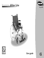
I n v a c a r e Atlas Lite ® ISO 9001 Yes, you can. User guide Foreword The information contained in this manual is subject to change without notice. Some information is submitted under copyright – all rights reserved. Any information in this document cannot be photocopied or duplicated without prior written authorization by Invacare. As the European and world leader manufacturer of wheelchairs, Invacare endeavours to supply a wide range of wheelchairs to meet all the needs of the user in everyday life. However, final selection of the wheelchair rests solely with the user and his/her qualified health advisor. Proper and efficient use of the wheelchair that you have chosen is based upon the medical prescription which was issued for you on the basis of your pathology and the nature of your disability. Your wheelchair is especially designed to be used inside, and with certain restrictions outside. Please comply with traffic regulations. Stamp of the Distributor Introduction Dear Customer Thank you for purchasing an Invacare wheelchair. This model was designed to provide you with all the benefits and features to meet your needs. Only quality components were selected for your wheelchair based upon rigorous inspections during the entire manufacturing process. This manual describes the operating limits of your wheelchair, maintenance operations and adjustments that you or your assistant can make. This product conforms to the requirements of Council directives 93/42/EEC related to medical devices class 1(one) product by application of following standards: NF EN ISO 14971 and NF EN 12182. However, all the repairs (except for inner tubes) as well as some adjustments, require specific technical training and, therefore, must be performed by your distributor. The I n v a c a r e Atlas Lite is designed for both indoor and outdoor use with the purpose of helping people who are not able to walk over a long distance. ® TABLE OF CONTENTS B. DESCRIPTION OF YOUR CHAIR A. GENERAL GUIDELINES Page 2 1. Safety and operating limits 1.1. Reaching an object from the chair 1.2. Sideways transferring to other seats 1.3. Tilting 1.4. Tilting, kerbs 1.5. Stairways 1.6. Slopes 3 5 6 6 7 7 2. Operating instructions 2.1. Folding and Unfolding the wheelchair 2.2. Wheelchair propulsion 2.3. Lifting the wheelchair 8 9 9 3. Safety inspection and maintenance 3.1. Performance control 3.2. General inspection 10 10 4. Transportation 4.1. Test report 4.2. Observation 4.3. Restraint systems 11 12 13 5. Warranty 5.1. Standard terms and condition 5.2. Limitation of liability 14 14 6. Summary of operating instructions 14 1. General 1.1. Introduction 1.2. General description 2. Adjustments 2.1. Seat elements 2.1.1 Padded seat upholstery 2.1.2 Rigid seats 2.1.3 Backrest type 2.1.4 Backrest upholstery 2.1.5 Footrest supports 2.1.6 Armrests 2.2. Frame 2.2.1 Side frame 2.2.2 Folding system 2.2.3 Seat height adjusment 2.3. Rear wheel 2.3.1 24" wheels 2.3.2 Handrims 2.3.3 Axles 2.4. Castors 2.5. Brakes 2.5.1 Manual brakes 2.5.2 Hub brakes 2.6. options 2.6.1 Seating options 2.6.2 Transit version 3 Specification and tool 3.1. Standard wheelchair specifications 3.2. Tools for adjustments and regular maintenance (Not supplied) 3.3 Dimensions Page 15 15 16 16 16 17 18 18 19 19 19 19 20 20 20 20 21 21 21 21 22 22 22 23 24 24 25 A GENERAL GUIDELINES 1. Safety and operating limits For a safe operation of your wheelchair, the following parameters should be observed : - Stability and balance Your wheelchair has been designed to provide the stability you need during normal daily activities. Any movement in the wheelchair will have an impact on the position of the centre of gravity, which may lead to the wheelchair tipping and a fall. To improve your safety when you move a lot or you transfer your weight from one place to another, we recommend using seat belts. - Weight distribution (figure 1) Many actions cause the user of a wheelchair to reach out, lean over or move about within the wheelchair and outside it. These movements cause a change to normal balance, centre of gravity (G) and weight distribution of the wheelchair. 1 - Weight Limit The maximum recommended weight of the user is 120 kg. However, the level of activity is an essential factor. For example, an active user who weighs 75 kg may subject the wheelchair to more stress than that of a user who weighs 100 kg. To this purpose, we recommend that you consult your retailer when choosing the model of wheelchair based upon your daily life style. 1.1 Reaching an object from the chair The limitations on reaching out from a wheelchair indicated in the following diagrams have been calculated based on a representative sample of wheelchair users: - Only the arms should be extended beyond the seat of the wheelchair. (figure 2). - The body and head should remain within the boundaries of the seat. (figure 3). 2 3 3 1.1.1 Leaning forward 1.1.2 Leaning backward Do not extend your chest over the armrest (figure 4). In order to reach an object in front of you, you must lean and bend down ; therefore, you must use the castors as a tool (pointing them forward) to maintain stability and balance. An accurate alignment of the wheels is essential for your safety (figure 5). Position wheelchair as close as possible to the desired object so that you can simply pick it up by stretching your arm while sitting in the chair in a normal position. In any case, do not lean backwards because you may cause the chair to tip (figures 6 and 7). 4 4 5 6 7 1.2 Sideways transferring to other seats This may be done without assistance provided that you are sufficiently mobile and have a strong enough torso. - Move the wheelchair as close as possible to the seat to which you would like to sit, with the castors pointed forward. Lock the wheels by applying the brakes. Move the weight of your body towards the seat (figure 8) - While moving from the wheelchair to the seat, your body will have little or no support. Where possible use a transfer board during transfers. - If you are more or less able to stand up and if your upper body is sufficiently strong and mobile, you can transfer forward to another seat. Fold the footplate up and push the footrest/legrest to the side, bend your body forward leaning on the two armrests and lift yourself up; then shift your body towards the place where you want to sit while distributing your weight to the arms and hands (figure 9). 8 ! Warning : - Position yourself as close as possible to the place where you wish to sit. - When transferring, position yourself as far back as possible in the seat to prevent breaking screws, damaging the seat upholstery or causing the wheelchair to tip forward. - Lock the two brakes ; they should not be used in any case as support for transfers. - Never stand on the footrests when you are getting in or out of the wheelchair (figure 10). 5 9 10 6 1.3 Tilting (balancing on the rear wheels) 1.4 Tilting, Kerbs For greater safety, this operation must be performed by an attendant. The attendant should be aware of the required physical effort and use appropriate positioning in order to relieve the strain on his/her back (keep a straight back and bend your knees during this operation). To tilt the wheelchair, the attendant must firmly grab the handles making sure both are properly fixed. Warn the occupant in the wheelchair before tilting it and remind him / her to lean backwards and make sure that both feet and hands of the user are clear of the wheels. Place a foot on the footstep tube and move continuously until the chair reaches the equilibrium point. At this stage, the assistant will feel a difference in weight distribution, which usually occurs at approximately 30°. At this point, the wheelchair can get over the obstacle easily. Finally, the attendant slowly and gradually lowers the front down to the ground, while firmly holding the handles. To get on the pavement : - Method 1 (figure 11) The attendant positions the wheelchair in front of the pavement facing forward. Attendant tilts the wheelchair backwards until the castors reach the pavement; attendant pushes the wheelchair forward until the rear wheels are against the kerb and again pushes the wheelchair until the rear wheels climb over the kerb. - Method 2 (figure 12) In this case, the attendant stays on the pavement and moves the wheelchair in a backwards position with the rear wheels against the kerb. The attendant tilts the wheelchair backwards until it is balanced and pulls the wheelchair with a steady movement until the rear wheels climb over the kerb ; then he / she lowers the castors, while making sure that the chair is far enough on the pavement so that the castors do not fall into empty space. ! Warning : - Be aware of detachable parts such as armrests or legrests : they must NEVER be used as lifting supports as they may be inadvertedly released, resulting in possible injury to the user and / or attendant. - Do not lower the wheelchair suddenly, even if it is several centimetres from the ground, as this may result in injury of the user. 11 12 To get off the pavement : The attendant positions the wheelchair facing forward on the pavement and tilts it backwards until it is balanced, then he/she pushes the wheelchair forward until the rear wheels touch the road after getting over the obstacle; then, he / she gradually lowers the castors to the ground. 1.5 Stairways Because this is a difficult movement, we recommend using two attendants, one in front of the wheelchair and one behind the wheelchair. To climb stairways (figure 13) : After tilting the wheelchair to the point of equilibrium, one assistant (at the back) holds the wheelchair up against the first step grasping the handles firmly to lift.. The second assistant, lifts the wheelchair above the stairs, while holding firmly a fixed part of the frame, and holds it while the first assistant takes a step and repeats the operation. 13 The wheelchair must not be lowered until the last step has been passed and the chair is clear of the stairs. To descend stairways : Same operation as above, however, in reverse order. ! Warning : - Do not attempt to lift the wheelchair by any removable parts (such as armrests, legrests or footrests). - Avoid using an escalator which may lead to serious injury in the event of a fall. 1.6 Slopes It is recommended to avoid using ramps with a slope higher than 9°. The wheelchair risks tipping over in the event of spinning or side movement (figure 14). 14 7 Upward slopes (figure 15) : 2. Operating instructions Lean the upper body forward and move the wheelchair forward with short quick pushes on the hand rims to maintain speed and direction control. If you want to rest, apply both brakes when stopping. 2.1 Unfolding and Folding the wheelchair 2.1.1 Unfolding the wheelchair (figure 18) : Downward slopes (figure 16) : Lean backward cautiosly and let the hand rims slide in your hands. Be ready to react at any moment to control speed and direction. 8 ! Warning : - Avoid turning suddenly and never try to climb and descend a ramp diagonally (figure 17). 15 16 - With one hand, grab the armrest or the seat support tube on one side of the wheelchair and slightly tilt it towards you (so that the rear wheel and castor lift from the ground) ; - With the other hand, push on the seat upholstery until the tube supporting the upholstery is fully unfolded. The seat upholstery must be fully extended ; - Then, engage the two manual brakes, open the footrest/ legrest and check the ground clearance (footrest/ground distance - see § B-2.1.5). You can now sit down in the wheelchair. 17 18 2.1.2 Folding the chair (figures 19 and 20) : 2.2 Wheelchair propulsion - Fold and lock the footrest/legrest toward the front of the wheelchair. - Swivel the plates into the vertical position. Using both hands, take the centre front and back edges of the seat upholstery and lift it. Or, tilt the wheelchair to one side and close it using the handles on the backrest. Wheelchair propulsion is provided by the handrims mounted on the wheels. ! Warning : - Fold the wheelchair while keeping the seat upholstery upwards to avoid damage by the folding system. ! Qualified medical and paramedical staff will be able to provide you with advice regarding the propulsion which is best adapted to your disability. 2.3. Lifting the wheelchair Preliminary folds the chair (see § 2.1.2), always lift the wheelchair by gripping the frame at the points (A) shown in the figure 21. ! Never lift the wheelchair by removable parts (armrests, footrests). Ensure the backrest canes are securely in place. A 19 20 21 9 3. Safety inspection and maintenance 3.2 General inspection 3.1 Performance control Your distributor, who has the required technical expertise, is responsible for any wheelchair repairs. We recommend that you take the wheelchair to your retailer at least once a year for a complete inspection. Regular maintenance allows the identification and replacement of defective and worn parts, which improves the daily operation of your wheelchair. As the user, you will be the first to notice the possible operational defects of your wheelchair. The following table indicates the easiest troubleshooting symptoms to identify and the preliminary inspection that you can perform. 10 In the event that the symptoms persist after adjusting the pressure in the tyres and tightening screws and nuts, please consult your retailer. The inner tubes of the wheels are the only components that you can repair yourself (see § B-2.3). The wheelchair swerves to the right The wheelchair swerves to the left The wheelchair turns or moves slowly The castors lift Creaking and clinking Play in the wheelchair Inspections Make sure that pressure in the pneumatic tyre is correct (cf. § B-2.3) Make sure that the bolts are tight Check the fork angle Make sure that the 2 castors come in contact with the ground at the same time Regular inspections to be performed by you or your assistants : a. General Make sure that the wheelchair folds and unfolds easily. Make sure that the wheelchair moves in a straight line. (no resistance or deviation) b. Manual brakes Make sure that the manual brakes do not touch the moving tyres. Make sure that the manual brakes operate easily. Make sure that the joints are not worn and do not have excessive play. c. Folding system Check the folding system for worn or distorted parts. d. Skirtguard/armrest upholstery Make sure that all the fittings are properly tightened. e. Armrests Make sure that the armrests are firmly attached, but easy to remove. f. Armpad Make sure that the armpads are in good condition. g. Seat and backrest upholstery Make sure that the upholstery is in good condition. h. Rear wheels Make sure that the wheel nuts and precision bearings are tight. Make sure that the wheels are parallel to the frame. i. Handrims Check for rough patches. j. Spokes Make sure that the spokes are not distorted, loose or broken. k. Castors Make sure that the axle is tight by turning the wheel the wheel must gradually come to a stop. l. Fork/steering tube Make sure that all the fittings are well tightened. m. Pneumatic and solid tyres Check the pressure of the pneumatic tyres (front =2,5 KPa, Rear = 3,5 KPa) check the wear of the solid tyre tread. n. Cleaning and Disinfection Cleaning: Use only damp clothes and gentle detergent. Do not use abrasive or scouring liquid. Do not use high pressure cleaning devices on ball bearings (front & rear wheels, fork axles) Disinfection: Spray or wipe disinfection using a tested and recognised product is permitted. A list of the current permitted disinfectants is available from the Robert Koch Institute at http://www.rki.de Make sure you dry the wheelchair if it is wet (e.g. after washing it or going out in the rain). 4. Transportation Transport of wheelchairs in vehicles The Invacare® Atlas Lite has been tested for safety in collisions according to ISO-7176-19:2001, Invacare® Atlas Lite can be used for transport in vehicles that have been specially adapted for this purpose. The wheelchair must be securely fastened in the vehicle according to the methods described on the following pages. Remember that the best solution is always to move the user from the wheelchair into a normal car seat. 4.1 Test report from dynamic safety restraint test (ISO-7176-19) Test no : BMF P602501D (fixed backrests) Customer : Invacare Rea AB, Date : 2006-08-16 Testing to be carried out Pulse specification : ISO-7176-19 Wheelchair Manufacturer : Invacare Portugal Lda Model : Atlas lite Weight : 16,5 kg (fixed) Configuration : Forward facing 11 Safety restraint device Manufacturer : Unwin Safety Systems Model : 4 Pt WWR/ATF/K/R Attachment device : Unwin Low Profile Rail User safety belt : Manufacturer: Unwin Safety Systems Model : 3 Pt WWR/HD/ATF/K/R Test dummy : Hybrid III - 75 kg Test configuration 12 Chassis : Height 50 cm Backrest : Fixed Seat : sling type Armrest : Standard Legrest : Swing out Rear wheel : 12" pneumatic Castor : 8" x 1/4" solid Accessories : Heel strap Tested : 2006-08-16 The safety restraint devices used in this test must be approved according to ISO-10542. We have chosen to work with Unwin, a well-known quality manufacturer of safety restraint devices for wheelchairs. 4.2 Observations before transport of wheelchairs in vehicles • We recommend that wheelchair users should transfer to the seat of the vehicle and use the installed restraint system of the vehicle whenever feasible. • The wheelchairs are tested in a basic configuration. The use in other configurations has not been tested. See user manual, section «Test report from dynamic safety restraint test», for test configuration. • Auxiliary wheelchair equipment is either secured to the wheelchair or removed from the wheelchair and secured in the vehicle during transit. (i.e. table trays). • Alterations or substitutions are not to be made to points of the wheelchair or to structural and frame parts without the written consent of Invacare®. • A wheelchair-anchored posture belt must be fitted across the wheelchair occupant in addition to the lap and diagonal and restraint (3-point belt). • Belt restraints are not to be held away from the body by wheelchair components or parts such as armrests, postural restraints, wheels, etc. (Picture 22) • The wheelchair must be securely fastened in the vehicle with an ISO 10542-2 approved 4-point belt system, according to the methods described in the manual. • The occupied wheelchair must be tied down in an forwardfacing configuration, with the parking brake applied. • The test dummy weight is 75 kg, according to ISO 7176-19, although the chairs are approved for users up to 120 kg. • The wheelchair backrest should be positioned as close as possible to 90 degrees. • If possible, a headrest should be used during transit, in order to reduce the risk of neck unjury. The headrest should be placed as high as possible. Please observe that even if these products and recommendations are provided in order to increase security and safety. Correct and incorrect placements of safety belt (picture 22). 4.3 Restraint systems (picture 23) * Non contractual picture, only for information ! Please refer to best practice recommended instructions from the safety belt manufacturer. A. Front restraints with straps 1. Connect the front straps around the frontal part of the frame. 2. Release brakes and tension front straps by pulling the wheelchair backwards from the rear. 3. Re-apply wheelchair brakes. B. Rear restraints 1. Attach the snap hooks on the rear straps to the frame just above the rear wheel attachments. 2. Tighten the straps. C. Lap belt 1. The lap belt is mounted on the back frame (picture 24). 2. Check that the lap belt on the wheelchair is correctly fastened. If lap belt on the wheelchair is missing we recommend that the user should transfer to the seat of the vehicle, if possible. D. Fastening of car safety belt The car safety belt should not be kept from the user’s body by the parts of the wheel chair. B D 22 13 23 C A 24 5. Summary of warranty terms 5.1 Standard Invacare terms and conditions 14 This is to certify that your manual wheelchair is warranted by Invacare for a period of 2 years for the frame, crossbars and all others parts, subject to the following conditions : - The manufacturer will not accept responsibility for damage caused by misuse or non-observance of the instructions set out in the user manual. - During the period of warranty, any parts that have become defective due to faulty workmanship or materials, will be renewed or repaired without charge by the Invacare dealer/ supplier. - The warranty will be forfeited should any unauthorised alteration be made to the equipment. - The Purchaser’s statutory rights under the Consumer Protection Act are not affected. 5.2 Limitation of liability This warranty does not extend to the consequential costs resulting from fault clearance, in particular freight and travel costs, loss of earnings, expenses, etc. Invacare shall not be liable for : - Natural wear and tear. - Inappropriate or incorrect use. - Defective assembly or setting-up by the purchaser or third parties. - Defective or neglectful treatment use of unsuitable spares. 6. Summary of operating instructions for optimal safety - Maximum user’s recommended weight : 120 kg. - Do not attempt to reach objects if you have to move forward in the seat. - Do not attempt to pick up objects from the floor by reaching down between your knees. - Do not lean over the top of the upholstery back to reach objects located behind you : this may cause you to tip over - Always engage both manual brakes simultaneously. - Manual brakes are parking brakes : they must not be used in any case to slow down the wheelchair or as support during transfers. - Do not tilt the wheelchair (down kerbs or steps) without using an assistant. - Do not carry in the stairways or escalator, user sited in the wheelchair whith only one attendant; this may cause serious injury. - Do not use the wheelchair unless it has the proper tyre pressure (front =2,5 KPa, Rear = 3,5 KPa) - Do not overinflate the tyres : this may cause the tyres to explode and cause bodily harm. - Do not expose the wheelchair to a temperature higher than 40°C. - To avoid injury, keep your fingers away from mobile parts (armrests, folding system, legrests/footrests), and maintain good posture before lifting the wheelchair. ! Avoid riding on wet areas as well as gravel, grass, etc. (sand and sea water particularly damage ball bearings). When using the wheelchair inside, we recommend using solid tyre castors, especially when riding on carpet. 1.2 General description (see photo) B. DESCRIPTION OF YOUR WHEELCHAIR 1. PRESENTATION 1.1 Introduction Your wheelchair has been factory set before you purchased it. However, it must be specifically adapted to your needs. The following detailed paragraphs describe the various functions and possible adjustments as well as available options. You can make some adjustments yourself, while others can be made only by your dealer. Important: based upon the selected model or options, your new Atlas Lite wheelchair may be equipped with all of the components or options which are described in the following pages. Your wheelchair is made of various parts and this manual describes only the main parts. We recommend that you become acquainted with the following terms in order to better understand your wheelchair operation : The seat consists of the seat and backrest upholstery, the backrest and armrests. This unit is designed to provide optimal comfort. The swing-away footrest support or legrest : this is the supporting part between the frame and the footrest which swivels to facilitate transfers and can be removed during transport. The footrest consists of an adjustable tube and the footplate which supports the foot. The folding frame consists of side frames and a folding system including the seat rails. These parts constitute the frame, which is the supporting component of the wheelchair and its strength is well tested (checked at 120 kg). ! This is a warning symbol ; you must imperatively follow the instructions that are provided in these paragraphs to prevent personal injuries as well as injuries to people around you ! The rear wheel consists of the wheel, axle and handrim. The rear wheels ensure the rear stability and allow the propulsion of the wheelchair using the handrims. They are mounted on a fixed wheel support brackets. 15 The castor consists of the front wheel and the fork. The castors provide front contact with the ground and determine the steering by the direction of the forks. 2. Adjustments 2.1 Seat elements 2.1.1 Padded seat upholstery The manual brake is a parking brake. The two manual brakes are used to secure the wheelchair when stationary. Armpad Backrest upholstery Armrest Backrest 16 Seat upholstery Rear wheel Rear wheel support Adjustable footrest tube Rear wheel axle Handrim Manual brake Footplate Folding frame Front wheel Swing away footrest It provides comfortable support to the user. Standard padded seat are not adjustable; in the event that they become slack, it is recommended to request your dealer to replace them. 2.1.2 Rigid seats : Toilet seats : they are removable allowing the folding of the wheelchair, simply lift the seat and put it away, then take hold of the 2 seat rails and pull them upwards. Repeat the operation in reverse order to unfold the wheelchair (see § 2.1.1). The upholstery and casing of the two seats will wear, please contact your dealer for possible replacement. ! Make sure that the seat is properly positioned on the 2 seat rails to provide safety and comfort for the user. Keep your fingers away from movable parts to prevent injuries during folding and unfolding ! 2.1.3 Backrests type Note : Dismounting backrest: it can be removed for transportation or to change the type, unscrew both buttons (A) until you can pull up the backrest canes, reverse the procedure to reinstall. Make sure that the backrest cane preset hole and the button thread hole are well aligned and firmly tighten the buttons until their complete locked position. ! To prevent falls or possible injury to the user and/or attendant as the backrest canes are used as a support to tilt and/or climb kerb or stairways, make sure that the backrest canes are severally tied up to the frame. - Fixed backrest of 10° (photos 1 and 1A) Those backrest do not require adjustments. - Folding backrest (photos 2 and 2A) To save space during transport, operate lever (A) by pulling or pushing it and fold the top of the backrest. A 1 1A To return to the initial position, bring the top in the vertical position; it locks automatically. ! Always make sure that the backrest is properly locked in place before the user settles down in the wheelchair to prevent any injuries ! - Reclining backrest 0° to 30°(photos 3 and 3A) Angle can be adjusted very easily which provides a comfortable rest position, there are 4 angles position by step of 10°. Simultaneously pull the levers (A) to provides the same angle on both sides, release the levers when you reach the desired angle.(photos 3-3A) Note : Push on the backrest canes before operating the levers, this is to release the auto-locked security system. ! It is recommended that this operation be performed only by the attendant. Always make sure that the backrest is locked in place to ensure perfect safety for the user. A 2 2A 17 Keep away fingers from moving parts (levers, cylinders, mechanisms, etc.) to prevent injuries ! Avoid operating levers (A) (photos 3-3A) during a sideways transfer, for example, in order to prevent destabilising the user’s position ! To ensure safety for the user, when backrest is reclined, we recommend to use anti-tippers (available as an option). ! Maintenance of reclining backrest mechanism varies with use. Please contact your Dealer. 2.1.4 Backrest upholstery 18 Padded backrest it provides excellent daily comfort for the user who does not need specific support for the upper body. In the event that the upholstered backrest slackens, ask for a replacement from your Dealer. 2.1.5 Footrest supports - Standard footrest supports (photo 4) they swing away during transfers and can be removed during transport. Operate lever (A) by pushing sideways and swivelling towards outside. To return to the initial position, align the footrest support it locks automatically. To remove the footrest support, simply pull up after unlocking the assembly. To refit it, brings the support up in the open position, align the holes (B) on the side mounting and press on, while still in the unlocked position. - Legrest (photo 5) performs the same operation as for the footrest support to swing away or remove the legrest, by operating lever (A) which unlocks the locking system. To adjust the angle upwards, support the leg and the front tube to the required position. To return legrest to lowest position, operate lever (B) by pulling up. A B B A A 3 3A 4 A 5 The calfpad swings away during transfers and is 3 height positions adjustable by sliding. - Footrests (photo 6) : the footplate can be lifted during transfers, footrests are height adjustable. Loosen the bolt (A) to adjust to the desired height, firmly tighten the bolt after adjustment. Straps for standard legrest : to ensure a good position of the feet. Calf strap attached to the footrest support are both adjustable by Velcro fasteners. 2.1.6 Armrests To remove armrest (photo 7), push down the push pin (A) simply pullthem up, reverse the procedure to reinsert making sure that the push pin (B) is properly engaged in its housing. Reverse the procedure to reinstall. Note : the armrests are mounted in pairs on the wheelchair ; whenever you remove them, remember that you have a right and a left side ! ! Note : the standard footrest supports and legrests are mounted in pairs on the wheelchair; whenever you remove them, remember that you have a right side and a left side ! 19 2.2 Frame 2.2.1 Side frame ! Never lift the wheelchair by the footrest supports or legrests ! Keep your fingers away from movable parts during folding, disassembling or adjustment to prevent injuries ! A Never lift the wheelchair by the armrests ! Keep your fingers away from movable parts during folding, disassembling or adjustment to prevent injuries ! The side frames are designed to accommodate fixation of the front and rear wheels. No adjustment is required on side frames. A B B 6 7 A 8 A 8A 2.2.2 Folding system It consists of two cross-bars which integrate the seat rails. To fold and unfold your wheelchair, see chapter A “ General ” paragraph 2.1. No adjustment is required on folding system. 2.2.3 Seat Height adjustment The Atlas Lite allows 2 seat heights 50 cm (A) or 47,5 cm (B), always delivered with 50 cm height (Photos 8-8A). To achieved 47,5 cm seat height, insert rear wheel quick release axle (see chapter 2.3.3 for detailed operation) into the chassis bearing (B). Loosen the front wheel bolt (6 mm Allen key), extract the nut from A and insert into B, firmly tighten the bolt. 20 2.3 Rear wheels Remove the rim assembly (tyre and inner tube), repair or replace the inner tube, reinsert in the tyre and reposition the assembly on the rim. Comply with the inflation pressure specified on the sidewall of the tyre. ! Never exceed the pressure specified on the sidewalls of the tyre, otherwise, the tyre may explode and cause injuries ! Pneumatic tyres wear out. In addition, the roughness of the ground surface and driving have an impact on their longevity. The pressure in the two tyres should be the same. Replace them regularly to avoid trouble caused by puncture. Please consult with your Dealer. 2.3.2 Handrims 2.3.1 24" Wheels The 24" (610 mm) rear wheels are spoked wheels. They can be delivered with pneumatic or solid tyre. A flat tyre (photo 9) must be removed in order to be repaired. They provide the wheelchair propulsion. They are made of anodized aluminium. ! Handrims are constantly in contact with your hands. Make sure that they are not damaged ! B A C A 9 10 10A 2.3.3 Axles (photo 10) 2.5 Brakes The Quick release axles connect the wheels and frame : Depress the button (A) and insert the axle in the bearing (B) of the chassis until it locks in place. The locking balls (C) must rise above the bearing. 2.5.1 Manual brakes No significant side clearance is allowed. To reduce clearance as much as possible (photo 10A), remove the axle and adjust the nut using a large appropriate key ; then block the axle with an appropriate open-end key. ! Make sure that the axle and the locking balls are clean. To prevent falls, it is essential that the button (A) and the locking balls (C) are disengaged providing a perfect lock of the rear wheels. The quick release axle is a precision part, take care of shocks and clean regularly to ensure the good working of the mechanism. 2.4 Castors The solid front wheels are available in 8" x 1 1/4" (200mm x 28 mm) diameter. B A C Manual brakes (photo 11) are designed to be used for parking position only. They should not be used to slow down the wheelchair or as a support during transfers. To operate the brakes, push both handles (A) simultaneously forward and make sure the wheelchair doesn't move at all. To make transfers easier, the handle (A) can be folded back : pull it upwards and then push it backwards. Note : brakes adjustments are based upon the diameter and type of the wheels. After repairing a flat tyre or in the event of wear of the pneumatic or solid tyre, you may need to adjust the brake(s). To adjust the brake(s), loosen the two screws (B) and slide the brake assembly to obtain the following value between the wheel and the brake shoe in unlocked position : Solid tyre X = 6 mm, Pneumatic tyre X = 5 mm B A A X 10 10A 11 21 ! Firmly tighten the screws (B) after adjustment. Keep your fingers away from movable parts to prevent injuries ! 2.5.2 Hub brakes Besides the functions provided by manual brakes, the hub brakes provide the slow down (for example, on a slope) and improved safety because they are still efficient when you have a flat tyre ! The specific adjustments of hub brakes must always be performed by your Dealer. ! Always operate the two brakes simultaneously and do not take slopes exceeding 5% to ensure perfect control of the wheelchair steering ! 2.6.1 Seating options To slow down, gradually pull the lever (A) upwards. To lock the brake in parking position, with the lever (A) tightened, push the lock (B) to engage it in the notches of the brake handle ; then pull the lock up to unlock. B ! 2.6 Options Attendant control : (photos 12 and 13) 22 To adjust braking : turn the screw (C) counter clockwise to increase braking force and turn clockwise to reduce it. - Anatomic headrest (photos 14 and 15) : it is mounted on a specific back brace. This mounting allows you to adjust the height by operating button (A), angle and depth using a two levers (B and B’) ; the cushion is also angle adjustable by operating the lever (B). B C 14 B' A 12 13 A 15 Note : make sure that you properly position the indexable levers so that they are not in the way or causing injury for the user or attendant. ! Do not adjust this option when the user leans over and make sure that their mounting to the backrest is correct to prevent injuries. - Back brace (photo 16) : it provides tension to the backrest upholstery and provides the attendant better ergonomics when pushing the wheelchair. - Transit version (photo 17) The wheelchair is designed to be driven only by the attendant. To facilitate sideways transfers and save space, the wheelchair is equipped with rear wheels of 12" (315 mm) with pneumatic or solid tyre. The manual brakes with extension lever are only accessible to the attendant; operate the handle (A) to lock the wheelchair in parking position. For brakes adjustments see § 2.5.1 Note : it swings away to facilitate the wheelchair folding; slightly loosen the button (A), pull up and swivel along the backrest until it is in vertical position. To reposition it, reverse the procedure and firmly tighten the button (A) making sure that the button is properly tighten (B). 23 ! Do not lift the chair by handling the back brace. There is a risk to unlocked the back brace by push it up. Keep your fingers away from movable parts to prevent injuries. B A A 16 17 3. Specifications and tool 3.2.Tools for adjustments and regular maintenance (not supplied) 3.1. Standard wheelchair specifications 24 Function Tool Brake 5 mm Allen key Footrest tube 8 mm open-end Wrench Screwdriver Pozidriv n°2 Armpad Screwdriver Pozidriv n°2 Castor 6 mm Allen key Maximum user weight : 120 kg Seat width : 38/41/43/45/48 cm Seat depth : 42 cm Floor/seat height : 50/47,5 cm Rear wheel : tyre 24" (610 mm) pneumatic Castors : 8" (200 mm) solid tyre Parking brake : Manual brake After sale and disposal recommendations Backrest : Fixed 10°, Folding or reclining • It is compulsary to use original Invacare spare parts which you can buy through any Invacare dealer. • For repair, please contact your local Invacare dealer. • Disposal : the metal parts can be disposed of for scrap metal through recycling. Plastic parts are disposed of as plastic scrap. Disposal must be carried out in accordance with the respective national regulation. Please apply to your municipal authorities/local government for details about local disposal companies. Armrests : Removable Footrest supports & Legrests : Removable and swing-away Seat upholstery : Black nylon on reinforced upholstery Frame : Steel, epoxy coated Wheelchair average weight : 16 kg ® ® ® 3.3. Dimensions Picture ������� Description Min/Max value Seat effective width (mm) 380/480 Overall width (mm) 585/685 575/675 Drum brake Width of folded wheelchair (mm) 300 Picture Description Backrest height including headrest (mm) ������� �������� ������ ����� 128 ���������� ������� ����������� N/A ������� ���� ����� ������ Static on obstacle ������� ������� ����������� 110 ������� �� ����� ������ Static on obstacle ���������� �������� ����� 600 ������� ������� ��������������� ������ Static on obstacle N/A ������� �������� ����� 10 Backrest angle ( 0° ) N/A 220 415/425 415/440 Wheelchair height when backrest is folded (mm) ������������� ������ ����� 830 Height from ground to back seat (mm) 460 ������� ����� Lenght without footrest (mm) 890/915 Backrest height (mm) ����������� 1090 Distance between front wheel and rear wheel (mm) 470/495 ������� ����� Overall lenght (mm) Total height (mm) Height from ground to front seat (mm) Min/Max value ����������� Bracket angle ( 0° ) Distance between footrest and seat (mm) Distance between armrest and backrest (mm) ������� 21 18,5 17 530 ��������� ����� Armrests Legrest Footrests Rear wheels ���������� ����� ����� 3 ������� ������ ���������� ������ 16 65 ������ ������������ ����� ����� 815 ������ ������� ������ ������ 120 420/500 ������� ������ ���� 870 ������������� �������� ������������ ������ 9 200 ������� ����� ���� N/A ������������� ���������� NF EN 1021-1 NF EN 1021-2 25 26 27 Invacare PORTUGAL Lda Rua Senhora de Campanhã 105 4369-001 Porto ® Yes, you can. ® Invacare n.v. Autobaan 22 8210 Loppem (Brugge) Belgium ( +32 (50) 831010 Fax +32 (50) 831011 ® Invacare A/S Sdr. Ringvej 39 2605 Brøndby Danmark ((kundeservice) +45 - (0) 3690 0000 Fax (kundeservice) +45 - (0) 3690 0001 ® Invacare Deutschland GmbH Kleislstraße 49 32457 Porta Westfalica Deutschland ((Technische Hotline) 01 80 - 5 26 22 64 Fax (Technische Hotline) 01 80-5 26 22 75 ® Invacare SA c/Areny s/n Poligon Industrial de Celrà 17460 Celrà (Girona) España ( +34 - (0) 972 - 49 32 00 Fax +34 - (0) 972 - 49 32 20 ® Invacare Poirier SAS Route de St Roch F-37230 Fondettes France ( +33 - (0) 2 47 62 64 66 Fax +33 - (0) 2 47 42 12 24 ® V2 Invacare Mecc San s.r.l. Via dei Pini, 62 I-36016 Thiene (VI) Italia ( +39 - (0) 445-380059 Fax +39 - (0) 445-380034 ® Invacare AS Grensesvingen 9 0603 Oslo Norge ((kundeservice) +47 - 22 57 95 10 Fax (kundeservice) +47 - 22 57 95 01 ® Invacare PORTUGAL Lda Rua Senhora de Campanhã 105 4369-001 Porto Portugal ( +351-225105946 Fax +351-225105739 ® Invacare AB Fagerstagatan 9 163 91 Spånga Sverige ((kundtjänst) +46 - (0) 8 761 70 90 Fax (kundtjänst) +46 - (0) 8 761 81 08 ® Invacare B.V. Celsiusstraat 46 NL-6716 BZ Ede The Nederland ( +31 - (0) 318 - 69 57 57 Fax +31 - (0) 318 - 69 57 58 ® ATL-G-01 UK 09/2006 - V2 Invacare Ltd South Road Bridgend Mid Glamorgan CF31 3PY United Kingdom ( (Customer Service) +44 - (0) 1656 - 647 327 Fax (Customer Service) +44 - (0) 1656 - 649 016