1
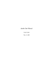
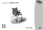
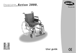
HiveLD
Advanced LED drivers
HiveLD McG
LED Driver
User Manual
10/10/2013, FW v1.0
© 2013, excited electrons, All rights reserved.
HiveLD
Advanced LED drivers
1. Introduction
The HiveLD (“Highly Versatile Led Driver“) is a constant current regulated led driver with a configurable
user interface. Using the built-in setup mode, the drivers functionality can be adapted by the user to their
individual needs.
The configuration parameters include the number of brightness levels, whose output currents can even
be configured independently of each other if desired. There is also the choice of using a brightness level
memory or not.
The settings can be stored in up to 3 preset slots to quickly recall different configurations for specific applications without having to change a number of individual settings every time.
Additionally the driver monitors battery voltage and board temperature. This way it can keep the light operating safely and prevent a sudden shut down when the battery is depleted.
2. Driver operation
This section describes the operation of the driver with the default configuration.
Basic operation
Level Switching Method: “Toggle OFF“ - The McGizmo way
To switch the output levels you have to switch the light OFF for a short time of less than 0.5 seconds (called
“Toggle Short“) (see setting 15 “Switching mode“). If the OFF time is longer than 0.5 seconds no level
change occurs. In this mode the ON time of the driver is not relevant for level switching.
Operating Method: “Persistent” - Output level memory
The driver memorizes the last output level (see setting 3 “Operating mode“). Level switching (“Toggle
Short”) advances to the next output level, from the last (highest) level the driver returns to the first (lowest) level.
Advanced features
Overtemperature protection (Signal: Quick single blink)
The driver steps the output down by one of the internal 21 brightness levels (see Settings 6 to 10) when the
overtemperature value (default: 50°C) is reached. If the temperature consequently drops below this threshold value again by a certain margin, the original brightness level is restored. This is particularly useful if the
light heats up temporarily because i. e. it has been laid down on a surface with a poor thermal conductivity.
The visual indication for the temperature output reduction is one quick blink of the LED after the reduction.
Note that the temperature is measured on the driver itself, however the head of the flashlight near the LED
is usually hotter than the driver board, so the light will be hotter than the actual threshold value before the
output would be reduced.
Low voltage output reduction (Signal: Quick double blink)
In order to maximize the remaining runtime as the battery depletes (especially for protected Li-Ion cells),
the driver steps down the brightness level automatically. The voltage threshold for this output reduction is
preconfigured for the commonly used Li-Ion rechargeable chemistries with 3.6 V or 3.7 V nominal voltage.
The reduction algorithm steps through the configured output levels. If there is less than 3 output levels the
driver uses pre-defined reduction steps of 50%, 15% and 1% of the configured maximum output. When the
lowest output level is reached, and the battery voltage nears the absolute minimum input voltage of 2.5V,
10/10/2013, FW v1.0
© 2013, excited electrons, All rights reserved.
HiveLD
Advanced LED drivers
the LED is blinking slowly to indicate that shut off is imminent.
The battery state of charge is determined when the driver is being powered on, thus the LED will come
on with a lower output level if the low voltage condition is met. When using protected Li-Ion batteries, this
prevents the protection circuit of the battery to cut off the cell immediately if the cell is nearly completely
discharged.
An output reduction due to low battery is indicated by a quick double blink of the LED just after reducing
the output.
3. Configuration of the driver (Setup mode)
Before the setup mode can be used, it needs to be unlocked by closing a jumper on the board. This could
either be done by a solder joint or with electrically conductive (silver filled) ink. Be extra careful not to short
out anything else on the board, please check thoroughly before putting the light back together!
If the jumper is opened again at some point later, the configuration will be frozen in the state it is at that
point.
Once unlocked on the hardware, to enter setup mode you have to execute a certain sequence of “long“
and “short“ toggles:
2x toggle long - 4x toggle short - 2x toggle long
Toggle short: toggle the power quickly in less than 0.5 seconds (the same as for switching levels)
Toggle long: toggle the power for 0.5 to 2 seconds
Note: Depending on the level switching mode (see setting 14), a TOGGLE is either defined by the driver being TURNED OFF
(Toggle OFF mode, default) or by being TURNED ON (Toggle ON mode) for the certain length of time.
Solder jumper, connect two sides to
unlock setup mode
After completing above sequence, the driver will start up in setup mode. The driver uses the main LED to
signal the setting numbers and their values in a fixed scheme, which is outlined in the diagram in Fig. 2. An
example of the actual pattern of flashes is given in Fig. 3.
The signaling pattern starts with a quick triple flash of the LED. After a short delay, a series of slower blinks
indicates the currently active setting number. After another delay, this is followed by a series of slightly faster
blinks showing the value of the current setting. The signal block is concluded with another triple flash.
Note: In case of a number being a double digit value, the second digit (tens) is signaled as quick double flashes,
10/10/2013, FW v1.0
© 2013, excited electrons, All rights reserved.
HiveLD
Advanced LED drivers
preceding the blinks with the regular speed for the remaining single digit number. For example the value “12“
would be represented by a double flash and two blinks, a “20” would be two double flashes and no regular blinks.
The user input happens by “turning off ” the driver during certain time frames within the signaling sequence.
These intervals are depicted on the right side of Fig. 1. and also in Fig. 2:
Period 1 - Go to next setting: If the power is turned off between the first and the second triple flash, i. e. while
signaling the setting number and value, the driver will advance to the next setting of the setup when it is
turned on again. No changes to the settings’ value are made.
Period 2 - Change setting value: Turning off the power after the second triple flash alters the current settings’
value. The exact sequence depends on whether the setting has just two possible states or more:
If the current setting is a two-stage setting (Yes - No), the input window (during which the LED is driven at a
medium brightness) is 1.5 seconds long and the end of the window is visualized by the LED being turned off.
Fig. 1: Setup signal pattern displaying current setting and its value, followed by the input window for changing
the settings’ value
10/10/2013, FW v1.0
© 2013, excited electrons, All rights reserved.
HiveLD
Advanced LED drivers
Fig. 2: Example of a setup signal pattern (main LED) for a multi-stage setting, showing setup setting 2 with a
set value of 3
In case of a multi-stage setting, the input time window is split into a 1.5 second period for increasing the
value, followed by another 1.5 second period for decreasing the value. As a visual indication, the LED output is slightly reduced when the “decrease value” period starts. The LED is turned off when the entire input
window is over (see also Fig. 3 for an illustration of this sequence).
If a change to the value has been made, the driver will then start up with same setting and signal the changed
value.
Period 3 - Do nothing: If the driver has not been turned off until after the end of the entire sequence (i. e.
when the main LED is turned off), it will return to the same setting without any changes.
Once all settings have been cycled through, the driver will exit setup mode and return to normal operation.
Practically this means that the setup mode can be easily left by toggling the power quickly several times.
4. Setup usage examples
The following walkthroughs are meant to give a step-by-step description for making changes to the configuration and assume a factory configuration. Also make sure that the hardware jumper on the board is closed.
Scenario 1: Changing the number of brightness levels from 4 to 3
First you will need to execute the setup toggle pattern (2x toggle long - 4x toggle short - 2x toggle long)
to enter setup mode. You will see the flashes of the driver signaling the first setting after you successfully
entered this pattern, if not just try again and make sure that you wait the 0.5 to 2 seconds of OFF time for
the toggle long inputs.
We will now want to move to setting 3 for changing the number of brightness levels. To do so you have to
turn off the light during “period 1” of the signaling sequence (see Fig. 1), i. e. before the second quick triple
flash. After doing this two times we have now entered setting 3.
To familiarize with the structure of the signaling pattern you should just watch it entirely first. As described
above, following the first triple flashes, the number of the setting is displayed as 3 slower flashes. After a
brief pause you will see 4 slightly faster flashes indicating that 4 output levels are currently programmed.The
second triple flash then indicates the start of the input window for changing the setting. Since it is a setting
that can have a value from 1 to 5 (a multi-stage setting), there will be a 1.5 second time frame (toggle UP
period), which you increase the setting value with if you turn off the light during that time. The LED is lit on
a medium level during this “toggle UP” period.
10/10/2013, FW v1.0
© 2013, excited electrons, All rights reserved.
HiveLD
Advanced LED drivers
Fig. 3: Settings are devided into two levels, circled numbers beneath settings denote default values
The following “toggle DOWN” period is indicated by the LED output being reduced. Turn the light off now
to decrease the setting value to 3. When you turn it back on you will see the signaling sequence for setting
3 again, but this time showing a value of 3.
Since this was the only change to make, we can now leave the setup by skipping over the remaining settings.
Just toggle the light off and on quickly 3 times to do so. Be sure you don’t inadvertedly change another setting by taking care that you turn off the light before the second triple flash in the signaling pattern.
Scenario 2: Modifying the brightness value of output level 1
If you would want to increase the first (lowest) brightness level of the 4 default levels you will have to change
setting 6. This is a setting in the level 2 of the setting structure.
After entering the setup mode (setup toggle pattern), we first have to go to setting 4 which lets us enter the
level 2 settings. So skip through settings 1 to 3 by turning the light off during period 1 of the signaling pattern.
Now being in setting 4 the driver will signal 4 slower blinks (setting number) and one faster blink (indicating
that setting 4 is currently set to “No”). By turning off the light after the second triple blink, we change this
setting to “Yes”, which would be signaled as two blinks for the setting value if you watch the entire signal
pattern after making the change.
Now you have to move to the next setting (which is setting 6 that we want to change) by turning off the
10/10/2013, FW v1.0
© 2013, excited electrons, All rights reserved.
HiveLD
Advanced LED drivers
light during period 1 of the signaling pattern. Once being in setting 6 we increase the value the desired
amount of times by turning the light off during the “toggle UP” input window.
After having changed the setting value we can leave the setup by skipping over all remaining settings as indicated in the setting structure.
5. Detailed explanation of the settings
The settings are devided into two groups (called levels below), the first group containing the more common settings that are likely to be used more often. To access the second group one has to change setting 4
(Enter Setup Level 2) to “Yes“ and then advance to the level 2 settings. Note that this means you will move
from setting 4 to setting 6 as shown in Fig. 3.
Level 1 settings:
Setting 1: Load preset
This setting is used to load the values of a saved preset that contains all relevant settings for the driver operation. Included in the presets are settings number 2 and 3, as well as 6 to 15. As detailed in Fig. 3, there are
predefined preset values already stored in the preset slots.
The default value for this setting is 0 (no blinks signaled), meaning no preset will be loaded. By changing this
settings‘ value to 1, 2, or 3, the corresponding preset data will be loaded as soon as the driver advances
to setting 2. This means one could still make changes to the just loaded setting values before leaving setup
mode.
Setting 2: Operation mode
This setting defines whether the last active brightness level is being memorized (“persistent“) or not (“volatile“). In volatile mode, the driver will always start up with the first brightness level (which by default is the
lowest) if there has been no “toggle short” event beforehand.
Setting 3: Number of Output levels
The number of output levels can be set to a value from 1 through 5.
Setting 4: Enter setup level 2
This setting has to be set to “Yes“ in order to access the “Level 2 settings” (settings 6 through 18). If it is left
unchanged the driver will move on to setting 5.
Setting 5: Save preset
This setting allows to save the currently active configuration to one of the three preset slots. See explanation
of setting 1 for details.
Level 2 settings:
Settings 6 to 10: Set Output levels 1 to 5
The brightness of the output levels in the currently active configuration can be changed directly through
these settings. Each level can be set individually to a brightness level value from 1 to 21 (lowest to highest
possible output level), i. e. it would be possible to configure the driver to use a different output level sequence like i . e. “High - Low - Medium”.
Note that the number of active output levels is determined by setting 3, so if for example the driver is set to use
three levels then changing the value of output levels 4 and 5 would have no effect.
10/10/2013, FW v1.0
© 2013, excited electrons, All rights reserved.
HiveLD
Advanced LED drivers
The graph below shows the relative output current of the 21 brightness levels relative to the maximum current. The output in amperes increases exponentially, but since the sensitivity of the eye scales logarithmically,
the output increase in lumens would appear to be somewhat linear.
Rela/ve current in % 100 90 80 70 60 50 40 30 20 10 0 1 3 5 7 9 11 13 15 17 19 21 Brightness level Setting 11: Use default output level values
When set to “Yes“, then changing the number of output levels (setting 3) will replace the brightness level
values in settings 6 to 10 with default output level values.
Number of
output levels
1
2
3
4
5
Level 1 brightness value
21
16
5
3
2
Level 2 brightness value
21
15
11
8
Level 3 brightness value
21
17
14
Level 4 brightness value
21
18
Level 5 brightness value
21
Setting 12: Thermal foldback
The threshold value for the overtemperature output reduction is defined through this setting. When the
temperature exceeds the threshold, the driver reduces the output to the next lower of the 21 brightness
levels. The default value of 6 corresponds to a threshold temperature of 60°C.
Setting 13: Voltage foldback
The low voltage output reduction algorithm operates based on the battery voltage. The available options
depend on the drivers input voltage range, for the HiveLD-P (Vin 2.7 V to 5 V) only single Li-Ion rechargeable cells can be used. Hence available choices are to use an absolute minimal output reduction (minimal),
or to use a reduction optimized for Li-Ion rechargeable cells that results in a longer remaining runtime after
the first reduction step (default).
Setting 14: Switching mode
Output level switching is done by a quick (less than approx. 0.5 s) switching action (called Toggle short).
In “ON time mode”, the toggle short condition is defined by the time the driver is powered ON before
switching off. In “OFF time mode”, the time beween powering off the driver and powering it on again de10/10/2013, FW v1.0
© 2013, excited electrons, All rights reserved.
HiveLD
Advanced LED drivers
termines whether a level change takes place.
Setting 15: Toggle short interval
This allows to set the toggle short interval (default 0.5 seconds) to either short or longer time.
Setting 16: Maximum current
All output levels scale to the maximum current defined here, that means output level 21 equals the maximum current. The maximum current is set in 100 mA increments, i. e. at a setting value of 10 the driver will
calibrate the output to a maximum current of 1000 mA. The value can not be set higher than the highest
current the driver hardware can safely provide, which is hard coded into the firmware.
If the value of this setting has been changed, the driver will automatically recalibrate AFTER LEAVING the
setup mode.
The actual calibration procedure first calibrates the minimum output level and then ramps up the output
until the desired maximum current is reached. When the procedure is finished the main LED will be turned
off and the driver will return in normal mode after toggling power. Should a problem occur during calibration
and the desired maximum current can’t be reached (for example because of a low battery voltage) then the
driver will signal this with a few blinks. In this case no changes are made to the current calibration settings.
Setting 17: Run calibration
If set to “Yes“ the driver will recalibrate the output current after leaving the setup mode.
Note: Recalibration should not be necessary during the lifetime of the driver.
Setting 18: Reset to defaults
This resets all settings to their factory default values.
10/10/2013, FW v1.0
© 2013, excited electrons, All rights reserved.