1
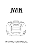
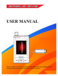
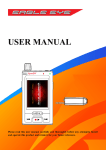
ABSOLARE Phono Stage
User Manual
2
Phono Stage User Guide 0.9
Contents 1. General Description .............................................................................................................. 4 2. Safety Issues and Warnings .................................................................................................. 4 3. Unpacking and Placement .................................................................................................... 5 4. Installing the Tubes .............................................................................................................. 6 5. Connecting the Cables .......................................................................................................... 8 5.1. Power cables .................................................................................................................. 8 5.2. Signal Cables .................................................................................................................. 8 6. Operating the Unit ................................................................................................................ 8 6.1. General Operating ......................................................................................................... 8 6.2. Installing/Changing Custom Load Resistors ................................................................... 9 7. Troubleshooting and Maintenance .................................................................................... 10 8. Technical Specs ................................................................................................................... 11 3
Phono Stage User Guide 0.9
1. General Description The ABSOLARE Phono Stage is a dual chassis phono preamplifier with an all tube
signal path and point-to-point construction. The first chassis contains the Signal
Stage. The second chassis contains the separate Power Supply. Inside the Power
Supply, transformers are also isolated from the DC regulators by an internal partition,
to further reduce noise and hum. There are two dedicated heater and signal power
transformers and also separate DC regulators for input and output sections of the
Signal Stage. Two adjustable loading resistance inputs are directly coupled to input
tubes. Balanced (XLR) and unbalanced (RCA) output versions are available.
2. Safety Issues and Warnings - Be sure the voltage setting of the unit matches the applied voltage to power input.
Operating voltage is fixed and can be changed by an authorized service agent only.
- Do not touch tubes while operating. Tubes are extremely hot devices and also
contain very high voltages.
- There are no serviceable parts inside either chassis, other than internal tubes and
custom loading resistors. Do not open bottom covers.
- Do not operate the unit without first connecting and locking all DC power cables.
4
Phono Stage User Guide 0.9
3. Unpacking and Placement The Signal Stage and Power Supply are contained in two separate chassis. After
opening the top cover of the crate, remove the upper layer of hard foam material.
You can then lift the units from the crate using the cloth underneath each chassis.
Both the Power Supply and the Signal Stage become very hot during operation. You
should always place them on feet and leave at least 2 inches (5 cm) clearance
above both units to allow sufficient ventilation.
Feet can affect the sound quality significantly. Feet should be placed directly under
the aluminium base plate, not the MDF/leather plate. There are three areas where
the Aluminium base plate is exposed through openings in the bottom MDF/leather
plate. These areas are where feet should be placed. You can use either three or
four feet. Adjusting their position will also affect the sound to varying degrees,
depending on the type of rack, location or interaction with other equipment. For most
situations the arrangement as shown in the diagram below is a good starting point.
5
Phono Stage User Guide 0.9
4. Installing the Tubes There are total of nine tubes in the Signal Section. Five are visible within the upper
recess on top of the chassis. Four are located inside the unit, accessible only by
removing the small cover on the rear panel.
Placement of the upper tubes is shown below:
You may receive the unit with the internal tubes already pre-installed. If this is not the
case, or you wish to replace them yourself, you should remove the four small hex
screws on the corners of the small cover on the rear panel.
6
Phono Stage User Guide 0.9
Once the small cover has been removed, four 6C45PI / WE417* tubes should be
installed into the four sockets that are visible within the chassis. Please check for the
correct orientation of tube pins before installing into the sockets.
*PLEASE NOTE: WE417 tubes have different pin configuration to 6C45PI tubes.
You must either have the WE417 version of the phono stage, or use a conversion
adapter. Otherwise the unit will not work and permanent damage may occur.
7
Phono Stage User Guide 0.9
5. Connecting the Cables 5.1. Power cables AC power input is via a standard IEC socket on the Power Supply. Operating voltage
can be changed by an authorized service agent only.
There are four DC power cables connecting the Power Supply and the Signal Stage.
Each DC connection has a different number of pins. The 2 pin cable connects to the
2 pin sockets, the 3 pin cable connects to the 3 pin socket etc. The DC connectors
lock into the corresponding socket with a twisting ring. Connect and lock all four DC
power cables before powering-up the system. Never connect or disconnect any
power cable while the unit is operating. Some of the pins carry high voltages, so it is
important to never touch any Power Supply DC Output sockets while the unit is
operating. Also wait at least 30 seconds beofre disconnecting any cables after
powering down the unit.
5.2. Signal Cables You can connect two separate arms/cartridges to the Signal Stage at the same time.
The selector switch between the inputs selects the active input channel. Ground
point is common for both input channels.
Output is single-ended RCA or transformer balanced XLR depending on the version.
6. Operating the Unit 6.1. General Operation ABSOLARE Phono Stage will be ready to operate seconds after turning on the
power, but attaining full performance may take 15 to 30 minutes. Expected tube life
is 5,000 to 10,000 hours.
Signal ground and chassis/power ground is separate inside the Signal Stage and
they are connected by a high pass filter to reduce hum and noise. The ground point
near the inputs is connected to the chassis ground. The outside parts of the RCA
output connectors are connected to signal ground. Balanced (XLR) version has
transformer balanced output on pins 2 and 3; pin 1 is connected to chassis ground.
There are no adjustments other than cartridge loading. As you can connect two
separate arms/cartridges to the signal stage at the same time, there are separate
loading options for each input. To provide more levels in total and a better match for
each cartridge, load values are not the same between channels. If the preset levels
do not match the desired value exactly, you can install your own load resistors for
each input channel (see section 6.2. for installing custom resistors).
8
Phono Stage User Guide 0.9
There are five factory fixed and one custom load level for each input.
Custom resistors can be accessed via input tube cover on the back of the unit.
Custom level is short circuited as factory default.
Input A load levels: 68 Ω, 150 Ω, 330 Ω, 680 Ω, 47 KΩ, (custom installed value)
Input B load levels: 47 Ω, 100 Ω, 220 Ω, 470 Ω, 1 KΩ, (custom installed value)
Input capacitance is fixed at 100pF.
You can use the 47K setting for MM cartridges.
6.2. Installing/Changing Custom Load Resistors Custom load resistors are reachable from under the small middle back cover. First
you should remove the four hex screws on the corners of the small cover on the rear
panel. Then you can change the resistors to any desired value. There are straight
wires in place of the resistors as the factory default.
9
Phono Stage User Guide 0.9
7. Troubleshooting and Maintenance Surface of the unit is dirty
Clean with a slightly damp cloth
No power indicator light on both units
Check AC line voltage, check the fuse of
the Power Supply unit
Power indicator light on Power Supply
but not on Signal Stage
- Check all DC power cords
Both indicator lights are on but tube
heaters are not glowing
- Check all DC power cords
Both indictaor lights are on, tube heaters
are glowing, but no sound
- Check all DC power cords
- Check the input selector
- Check resistor loading (custom level is
short circuited as factory default)
- Check output cables
Noise / hum in the sound
- Check grounding of input cables
- Check resistor loading (47K setting may
increase noise)
Input selector does not work
- Check all DC power cords
If the problem is persistent, contact your nearest ABSOLARE dealer.
10
Phono Stage User Guide 0.9
8. Technical Specifications -
All tube signal path: 4 x 6C45PI, 3 x ECC83 (12AX7), 2 x ECC82 (12AU7).
-
Two box design: 1 Signal Section; 1 Power Supply.
-
Separate transformers for heaters and signal power.
-
Isolated transformer section within the Power Supply.
-
Separate DC regulators for input and output section in the Signal Stage.
-
Point-to-point construction.
-
Two independent inputs (A/B) with input selector switch – 5 factory fixed, 1
custom cartridge loading level for each input. Custom resistors can be
accessed via input tube cover on the back of the unit.
-
Input A loading: 68 ohm, 150 ohm, 330 ohm, 680 ohm, 47 Kohm, (custom
value).
-
Input B loading: 47 ohm, 100ohm, 220 ohm, 470 ohm, 1 Kohm, (custom
value).
-
Input capacitance: 100 pF.
-
Direct coupling to input (no step-up transformer).
-
61 dB fixed gain.
-
Single-ended, or balanced output options.
-
Output impedance: 325 ohms
-
Bandwidth: 20 Hz - 20 KHz.
-
Standard RIAA equalization.
-
Dimensions: 38.2 x 54.5 x 14.6 cm (W x D x H), per chassis, excluding feet.
-
Weight: 20 kg (Signal Section); 22 kg (Power Supply).
11
Phono Stage User Guide 0.9
ABSOLARE USA LLC
40 Pemberton Road, Nashua New Hampshire, 03063
Phone: +212-229-1842
E-mail: [email protected]
ABSOLARE SERVICE EUROPE
Mozartstraat 157, 1962AL Heemskerk, Netherlands
Phone: +31 61 399 3049
E-mail: [email protected]
© 2015 ABSOLARE