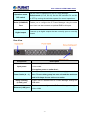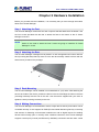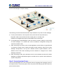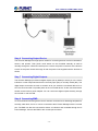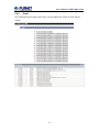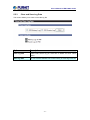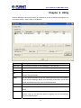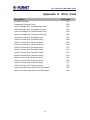
1
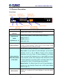
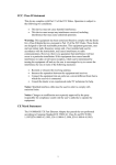
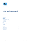
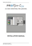
12-Port IP Power Manager ►IPM-1200x Series User’s Manual of IPM-1200x Series Copyright Copyright © 2013 by PLANET Technology Corp. All rights reserved. No part of this publication may be reproduced, transmitted, transcribed, stored in a retrieval system, or translated into any language or computer language, in any form or by any means, electronic, mechanical, magnetic, optical, chemical, manual or otherwise, without the prior written permission of PLANET. PLANET makes no representations or warranties, either expressed or implied, with respect to the contents hereof and specifically disclaims any warranties, merchantability or fitness for any particular purpose. Any software described in this manual is sold or licensed "as is". Should the programs prove defective following their purchase, the buyer (and not PLANET, its distributor, or its dealer) assumes the entire cost of all necessary servicing, repair, and any incidental or consequential damages resulting from any defect in the software. Further, PLANET reserves the right to revise this publication and to make changes from time to time in the contents hereof without obligation to notify any person of such revision or changes. All brand and product names mentioned in this manual are trademarks and/or registered trademarks of their respective holders. Federal Communication Commission Interference Statement This equipment has been tested and found to comply with the limits for a Class B digital device, pursuant to Part 15 of FCC Rules. These limits are designed to provide reasonable protection against harmful interference in a residential installation. This equipment generates, uses, and can radiate radio frequency energy and, if not installed and used in accordance with the instructions, may cause harmful interference to radio communications. However, there is no guarantee that interference will not occur in a particular installation. If this equipment does cause harmful interference to radio or television reception, which can be determined by turning the equipment off and on, the user is encouraged to try to correct the interference by one or more of the following measures: 1. Reorient or relocate the receiving antenna. 2. Increase the separation between the equipment and receiver. 3. Connect the equipment into an outlet on a circuit different from that to which the receiver is connected. 4. Consult the dealer or an experienced radio technician for help. FCC Caution To assure continued compliance. (example-use only shielded interface cables when connecting to computer or peripheral devices). Any changes or modifications not expressly approved by the party responsible for compliance could void the user’s authority to operate the equipment. This device complies with Part 15 of the FCC Rules. Operation is subject to the Following two conditions: (1) This device may not cause harmful interference, and (2) this Device must accept any interference received, including interference that may cause undesired operation. Federal Communication Commission (FCC) Radiation Exposure Statement This equipment complies with FCC radiation exposure set forth for an uncontrolled environment. In order to avoid the possibility of exceeding the FCC radio frequency exposure limits, human proximity to the antenna shall not be less than 20 cm (8 inches) during normal operation. Safety This equipment is designed with the utmost care for the safety of those who install and use it. However, special attention must be paid to the dangers of electric shock and static electricity when working with electrical equipment. All guidelines of this and of the User’s Manual of IPM-1200x Series computer manufacture must therefore be allowed at all times to ensure the safe use of the equipment. CE Mark Warning This is a Class A product. In a domestic environment, this product may cause radio interference, in which case the user may be required to take adequate measures. WEEE Regulation To avoid the potential effects on the environment and human health as a result of the presence of hazardous substances in electrical and electronic equipment, end users of electrical and electronic equipment should understand the meaning of the crossed-out wheeled bin symbol. Do not dispose of WEEE as unsorted municipal waste and have to collect such WEEE separately. Revision User’s Manual for PLANET 12-Port IP Power Manager Model: IP POWER MANAGER Rev: 1.0 (Jan. 2013) Part No. EM-IPM1200x_Series_v1.0 User’s Manual of IPM-1200x Series TABLE OF CONTENTS CHAPTER 1 INTRODUCTION.............................................................1 1.1 PACKAGE CONTENTS ......................................................................................................................1 1.2 PRODUCT DESCRIPTION ..................................................................................................................2 1.3 FEATURES .......................................................................................................................................4 1.4 PRODUCT SPECIFICATION ................................................................................................................5 1.5 PHYSICAL DESCRIPTION .................................................................................................................8 CHAPTER 2 HARDWARE INSTALLATION................................... 10 CHAPTER 3 QUICK SETUP............................................................... 17 CHAPTER 4 CONFIGURE WITH CONSOLE ................................ 21 4.1 RUN HYPER TERMINAL .................................................................................................................21 4.2 IP POWER MANAGER CONFIGURATION...........................................................................................23 4.2.1 System Group...............................................................................................................24 4.2.2 Control Group ..............................................................................................................25 4.3 OUTLETS CONTROL ...............................................................................................................26 4.4 ACCESS CONTROL..................................................................................................................27 4.5 TRAP RECEIVER TABLE ..........................................................................................................28 4.6 RESET CONFIGURATION TO DEFAULT ....................................................................................29 4.7 RESTART IP POWER MANAGER ..............................................................................................29 4.8 EXIT .......................................................................................................................................30 CHAPTER 5 WEB CONFIGURATION............................................. 31 5.1 POWER MANAGEMENT ..........................................................................................................32 5.1.1 Status ............................................................................................................................32 5.1.2 Control..........................................................................................................................32 5.1.3 Schedule .......................................................................................................................34 5.2 POWER ENVIRONMENT .................................................................................................................35 5.2.1 Status ............................................................................................................................35 5.2.2 Configuration ...............................................................................................................35 5.2.3 Alarm............................................................................................................................37 5.3 POWER SYSTEM .....................................................................................................................37 5.3.1 Configuration ...............................................................................................................37 5.3.3 Date & Time .................................................................................................................40 5.3.4 Trap Receivers..............................................................................................................41 5.3.5 WakeOnLAN................................................................................................................42 5.3.6 Email Notification ........................................................................................................43 5.3.7 Upgrade ........................................................................................................................45 5.3.8 External Links ..............................................................................................................45 User’s Manual of IPM-1200x Series 5.4 NETWORK ..............................................................................................................................46 5.4.1 Configuration ...............................................................................................................46 5.4.2 Control..........................................................................................................................47 5.4.3 Access Control .............................................................................................................48 5.5 LOGS ......................................................................................................................................48 5.5.1 History..........................................................................................................................49 5.5.2 Event ............................................................................................................................50 5.5.3 Clear and Save Log Data..............................................................................................51 CHAPTER 6 UTILITY ..................................................................... 52 APPENDIX A ERROR CODE........................................................... 54 APPENDIX B GLOSSARY ................................................................ 55 User’s Manual of IPM-1200x Series Chapter 1 Introduction Thank you for purchasing PLANET IP Power Manager. This manual guides you on how to install and properly use the IP Power Manager in order to take full advantage of its features. 1.1 Package Contents Make sure that you have the following items: 1 x IP Power Manager 1 x Power Cord 1 x User’s Manual CD 1 x Quick Installation Guide 1 x Console Cable 2 x Rack Mount Ear 1 x USB Cable 4 x Feet 2 x U-type handle 11 x Flathead Screw 5 x Roundhead Screw NOTE: 1. If any of the above items are missing, please contact your dealer immediately. 2. Using the power supply that is not the one included in Internet Camera packet will cause damage and void the warranty for this product. -1- User’s Manual of IPM-1200x Series 1.2 Product Description Remotely reboot anything from anywhere PLANET is glad to introduce 12-Port IP Power Management device. The IPM-1200x Series provides the useful function of managing power for any combination to connect with itself. With the innovative IP-based technology, PLANET has made the traditional power management equipment into true networking devices. Intelligent Power Management Coming with 12 power outlets, each of them can be controlled or monitored individual. You can control those power outlets via the console or web interfaces. You can also use the front panel to operate the power outlets. Provides 7-Segment LED and port status indicators, users can now easily the status of the IPM-1200x Series immediately, without login configure interface. -2- User’s Manual of IPM-1200x Series Easy Maintenance and Configuration In addition to manual remote control, the IPM-1200x Series provides event-triggered or schedule-based control to turn connected equipment on or off or to reboot systems. The IPM-1200x Series is easily configured with its Plug-and-Play ability. The IPM-1200x Series keeps a detailed log off all connected devices so that in case of severe errors from some devices, the status or failures can easily be solved. Cascade controls up to 6 IPM from single console The IPM-1200x Series can be daisy-chained to manage even more devices, so your server room management can expand in step with your company's growth. For ease of management, this allows IT administrators to completely control and IT device from a single user interface. EMD (Environmental Monitoring Device) The IPM-1200x Series has equipped with a console port for connecting an EMD (Environmental Monitoring Device) for sensing temperature and humidity along with two alarms that can be activated when the sensors show unusual values. The IPM-1200x Series is provided two digital outputs for connecting status indicators or digital switches. When users creating a new server room or the environment had been monitoring, the IPM-1200x Series is the best choice for fit the requirement. -3- User’s Manual of IPM-1200x Series 1.3 Features ¾ Hardware 19" rack mount 1U size design Cascode controls up to 72 outlets from Daisy-chaining port 12 LEDs shows power status for each power outlet 7 segment LED shows current, voltage or frequency, error code and the number of Daisy-chaining Twelve power outlets that can be turned on or off in multiple ways, with easy monitoring of current consumption Activate extended devices via digital outputs Versatile sensors supported through EMD (Environmental Monitoring Device) inputs ¾ Power Distribution Maximum Amps/Inlet: IEC 20A / 1 inlet (IPM-12001) Maximum Amps/Inlet: IEC 16A / 1 inlet (IPM-12002) Maximum Amps/Outlet: IEC 10A / 12 outlets -4- User’s Manual of IPM-1200x Series Supports multiple power control methods – Wake on LAN, System After AC Back, Kill the Power ¾ Remote Access Remote power control via TCP/IP and a built in 10/100 Mbps Ethernet port Comprehensive power management and flexible configuration through web browser, NMS, Telnet, SNMP, or HyperTerminal (console) ¾ Multi browser support (IE, Google, Firefox, Safari, Opera, Netscape) Management To calculate the power consumption on hourly basis, and have an accumulation of daily Provide detail data-logging for statistical analysis and diagnostic then auto email daily history report Event notification by pop-up/Sending Trap or E-Mail for events notification Set over-current watchdog for each outlet Power-on sequencing -Intelligently turn on/off devices based on event occurrence or planned schedule Supports Management Information Base (MIB) files for SNMP Upgrade utility for easy firmware upgrade ¾ Security Support Secure Socket Layer V3 and Secure Shell V1 protocols Administrator and multiple users with password protection for double-layer security IP Filter -Address-specific IP security masks to prevent unauthorized access 1.4 Product Specification Product IPM-12001 IPM-12002 Hardware Specification Output Power Port 12 Input Power Port 1 Network Connector 1 x RJ-45 port for 10/100Base-TX Console Port 1 x RS-232 RJ-45 serial port Digital Output 2 Daisy chaining Port 2 x USB 2.0 -5- User’s Manual of IPM-1200x Series Daisy chaining mode Auto / Manual Button Reset Output Power : ON / OFF LED Input status indicator : Volts/Amps/Hz/Error code and daisy chained IPM Power Distribution AC Input 100~125V, 20A, 50~60Hz 200~240V, 16A, 50~60Hz AC Output 100~125V, 50~60Hz 200~240V, 50~60Hz Load Max. 10Amp each outlet or Max. 10Amp total for Outlet A~C. Same as D~F, G~I, J~L Inlet Connector 1 x IEC320 C20 Outlet Connector 12 x IEC320 C13 Management User Account Management Utility Security 10 Web Browser, SNMP software, Windows base utility, Telnet, Hyper Terminal (via console) IP filter / Secure 128-bit SSL encryption Standards Conformance Computer Interface Regulation Compliance IEEE 802.3 10Base-T IEEE 802.3u 100Base-TX CE, FCC System Unit Operating Temperature 0 ~ 40 Degree C Operating humidity 10% ~ 80% Dimension (W x D x H) 436 x 300 x 44 mm Weight 4.2kg Installation 1U Product IPM-EMD Hardware Specification Digital Input 2 -6- User’s Manual of IPM-1200x Series LED Display Power / Status Console Port 1 x RS-232 RJ-45 serial port Monitoring Temperate 0 ~ 80 Degree C Monitoring Humidity 10 ~ 90% Dimensions (W x D x H) 57.4 x 37.6 x 29.2mm Weight 35g -7- User’s Manual of IPM-1200x Series 1.5 Physical Description Front View Component Input power status indicator Description Display power status for the input power G1. Display power status for each power outlet A through L. Output power status indicator (A ~ L) Gray: power off Green: power on Red: power fault Display input current, voltage, frequency, error code and the Status indicator number of Daisy-chaining. Please refer to “Error codes” under the appendix for a list of all error codes. Set the mode of Daisy-chaining for IP POWER MANAGER. Auto mode: For the master IP Power Manager, set all the DIP switches of the C- link to ON by moving all the switches downward; for all the other IP Power Manager in the Daisy Daisy-chaining Chain, set all the DIP switches of the C- link to OFF by moving Mode DIP Switch all the switches upward. After setting the DIP switches for all the (C-link DIP) IP Power Manager in the Daisy Chain, the Daisy Chain ID can be assigned for each IP Power Manager automatically. Manual mode: The Daisy Chain ID for all IP Power Manager is assigned by user manually. Please refer to DIP Switch Setting Table on page 15. Reset button Enable you to reset the IP Power Manager in case the system locks up. -8- User’s Manual of IPM-1200x Series Operation mode DIP switch Serial (CONSOLE) Port Digital output Set the mode of operation for the IP Power Manager. Default mode (S1 off, S2 off): Set the DIP switches S1 and S2 to OFF by moving the switches upward for normal operations. Enable you to configure the IP Power Manager using the serial port. User can also connect an optional EMD to this port. Connect up to digital outputs that are normally open or normally closed. Rear View Component Description Connect to a power outlet Input power 1-inlet model: G1 supplies power to outlet A to L Connect a device to each power outlet to supply power to it. Power Outlet (A ~ L) Note: Three outlets group into one unit and the maximum load is 10 Amps for one unit or one outlet. Daisy-chaining (C-link ) port Ethernet (LAN) port Enable user to cascade next IP Power Manager through an USB cable. Enable user to configure the IP Power Manager through a LAN or WAN -9- User’s Manual of IPM-1200x Series Chapter 2 Hardware Installation Before you proceed with the installation, it is necessary that you have enough information about the IP Power Manager. Step 1 Attaching the Feet The IP Power Manager comes with four feet or spacers that are attached to the bottom. Use the four screws provided with the feet to attach the feet to the bottom of the IP Power Manager as shown: NOTE: Users do not need to attach the feet if users are going to install the IP Power Manager in a rack. Step 2 Attaching the Ears The IP Power Manager is designed to be placed in a rack arrangement and comes with two ears (mounting brackets) that help users to move the device easily. Attach each ear with the three screws provided in the package. Step 3 Rack Mounting The IP Power Manager can be installed in most standard 19” (1U) racks. After attaching the ears to each side of the device, position the device in the rack and align the holes in the ears (mounting brackets) with the hole in the rack. Use the screws supplied with your racks to tighten the ears (mounting brackets) to the rack. Step 4 Making Connections The IP Power Manager can be attached to twelve output devices whose power status can be controlled remotely. It also supports an EMD (Environmental Monitoring Device) connecting with sensors for detecting environmental conditions as well as digital outputs for enabling devices with normally open or normally close conditions. Moreover, the IP Power Manager supports a serial port (console) and Ethernet (LAN/WAN) connection that lets users control - 10 - User’s Manual of IPM-1200x Series the IP Power Manager’s outputs remotely. The following procedure describes the basic steps needed to set up the IP Power Manager: a. To set up the hardware, connect power to the power inlet and output devices to the power outlets. Connect devices with normally open or normally close conditions to the digital output ports, and an EMD to the console port. b. To configure the IP Power Manager, users can use the console or LAN port. Connect the IP Power Manager to a console and a LAN to enable its configuration through the console or browser menu. c. After connecting to a console, use a console application such as Telnet or HyperTerminal to access the console menu. Select the System Group submenu under the IP Power Manager Configuration to set up the IP address and the system date/time. This IP address will be used while accessing the web interface to configure the IP Power Manager parameters. d. After connecting to LAN, open a browser from a PC in the network and use the IP Power Manager’s IP address specified through the console menu to open the web interface for system configuration. Step 5 Connecting Input Power The IP Power Manager has an IEC C20 power inlet for supplying and managing power for the output devices. Connect the power cord to the power inlet and plug the other end into a power outlet as shown: - 11 - User’s Manual of IPM-1200x Series Step 6 Connecting Output Device The IP Power Manager has eight power outlets for connecting devices such as workstations, servers, and printers. Their power on/off status can be controlled manually as well as remotely through the LAN and Console ports. Connect the power connectors of the devices to each of the power outlets A through H with the power cords supplied with the devices as shown: Step 7 Connecting Digital Outputs The IP Power Manager provides two digital outputs (NO by default) to which you can connect indicators or other output devices that are normally open (NO) or normally closed (NC). The digital output connectors are work as a switch to let you switch the connected device On or Off. The connectors will not provide power to the connected device. So the connected device should connect with its power adapter. You can control the digital outputs remotely through the console or over the LAN. Step 8 Connecting EMD An environmental monitoring device that is sensors connected to for detecting temperature, humidity, water level, and so on can be connected to the IP Power Manager with the console port. The EMD can also be connected to alarms or indicators and controlled through the IP Power Manager. Connect the EMD to the console port as shown: - 12 - User’s Manual of IPM-1200x Series After connecting to EMD, open a browser from a PC in the network. The temperature and humidity status is automatically displayed on the IP Power Manager Status page. Step 9 Connecting The Console You can control the output devices and manage their power status through the console port with serial connection. Use the bundled serial cable to connect the COM port of your PC and the CONSOLE port of the IP Power Manager as shown. Then you can run Hyper Terminal to control and manage your IP Power Manager. Step 10 Connecting LAN or WAN The IP Power Manager has an RJ-45 LAN connector that enables you to monitor and manage the power outlets and digital outputs over the network. The IP Power Manager has a graphic user interface that allows you to control the device through a web browser. Connect the IP Power Manager to a free port on your switch using an Ethernet cable. You can then control the IP Power Manager from your PC or laptop. When the network has installed a router, you can also use your mobile phone or PDA that is web browser supported and - 13 - User’s Manual of IPM-1200x Series connected to Internet to control IP Power Manager. Step 11 Daisy Chaining To manage more devices, up to 5 additional IP Power Manager R can be daisy chained to the first unit. Follow instructions below to set up a daisy chained installation. 1. For each IP Power Manager that you add to the chain, use USB cables to connect it to the parent IP Power Manager’s C-Link Port. The upper C-Link port( Manager is connected to lower C-Link port( C-Link port( ) of child IP Power ) of its parent IP Power Manager and the lower ) of the lowest level IP Power Manager is connected to the highest level parent’s upper C-Link port( ) to form a cyclic(ring) structure as illustrated in the following figure. 2. The daisy chained installation can operate in Auto mode or Manual mode. Use Daisy-chaining Mode DIP Switch (C-link DIP) to set the operation mode. Auto mode: For the master IP Power Manager, set all the DIP switches of the C- link to ON by moving all the switches downward; for all the other IP Power Manager in the Daisy Chain, set all the DIP switches of the C- link to OFF by moving all the switches upward. After setting the DIP switches for all the IP Power Managers in the Daisy Chain, the Daisy Chain ID can be assigned for each IP Power Manager automatically. - 14 - User’s Manual of IPM-1200x Series DIP Switch Setting Table for Daisy Chain ID in Auto mode DIP 1 DIP 2 DIP 3 DIP 4 Daisy Chain ID OFF OFF OFF OFF Slave01 to Slave05, automatically assigned by IP POWER MANAGER ON ON ON ON Master Down: ON ; Up: OFF Manual mode: Use DIP switches on the front panel to set the (Daisy Chain) ID number for each IP Power Manager that you add to the chain. You may set Daisy Chain ID for the first unit (Master) to 0 (DIP Switches: On, On, On, On) and the ID for the second unit (Slave 01) to 1(DIP Switches: On, On, On, OFF), etc. The DIP Switch Setting Table for Daisy Chain ID is described in the following table. DIP Switch Setting Table for Daisy Chain ID in Manual mode DIP 1 DIP 2 DIP 3 DIP 4 Daisy Chain ID OFF OFF OFF OFF 15 OFF OFF OFF ON 14 OFF OFF ON OFF 13 OFF OFF ON ON 12 OFF ON OFF OFF 11 OFF ON OFF ON 10 OFF ON ON OFF 9 OFF ON ON ON 8 ON OFF OFF OFF 7 ON OFF OFF ON 6 ON OFF ON OFF 5 ON OFF ON ON 4 ON ON OFF OFF 3 ON ON OFF ON 2 ON ON ON OFF 1 ON ON ON ON 0 Down: ON ; Up: OFF - 15 - User’s Manual of IPM-1200x Series 3. After all the IP Power Managers have been set up, power on all the IP Power Manager. NOTE: The total length of all USB cables in the chain must not exceed 8 meters. The specification of USB cable is illustrated in following figure. - 16 - User’s Manual of IPM-1200x Series Chapter 3 Quick Setup The following procedure describes the basic steps needed to set up the IP Power Manager: 1. Please insert User’s Manual and Utility CD into the CD-ROM drive to initiate the autorun program. Once completed a menu screen will appear. 2. Click on “Initial Utility” hyper link to initiate the installation. If the autorun program is not process in your PC, you can click the “Start” button and choose “Run”. (Suppose “E” is your CD-ROM drive). When the dialog box appears, enter “E:\Utility\Setup.exe” and press enter key. You will see the dialog box as below. 3. Please press “Discover” button to find out your IP Power Manager. - 17 - User’s Manual of IPM-1200x Series 4. Please select your IP Power Manager in the Device List and click “Modify” button to enter the user account and password. In default, user account and password is “admin”. Please press “OK”. 5. In default, IP Power Manager is DHCP Client enable. If you don’t have DHCP Server in your network, please click “Set IP” button. Then enter a new IP address that in the same segment of your configuration PC. Please press “OK”. - 18 - User’s Manual of IPM-1200x Series 6. Please press “Browse” button, then you will see a dialog box asking you to enter the User Name and Password. In default, please enter “admin / admin” as your User Name and Password for first time configure IP Power Manager. Please press “OK”. 7. Then the IP Power Manager configuration web page will appear as below. You can check and start the management of the IP Power Manager. - 19 - User’s Manual of IPM-1200x Series - 20 - User’s Manual of IPM-1200x Series Chapter 4 Configure With Console The IP Power Manager has provided a serial port that enables you to configure and control the system through your PC’s RS-232 serial (COM) port. Use the serial cable provided to connect the console port to your PC’s COM port as described in “Connecting the console”. This section describes how to use a console application to control the IP Power Manager and configure its settings such as its IP address, outlet control parameters, access control table, and trap receivers table. 4.1 Run Hyper Terminal Follow these steps to start HyperTerminal and communicate with the IP Power Manager: 1. To start HyperTerminal, click Start ==> Programs ==> Accessories ==> Communications ==> HyperTerminal from the Windows Start button. 2. A New Connection opens. Type a name for the connection in the Name field and select an icon for the connection. Click OK when done. 3. From the Connect To drop-down box, select the COM port that IP Power Manager connected. Click OK when done. - 21 - User’s Manual of IPM-1200x Series 4. The Properties window opens. Click” Restore Defaults” to use the default settings. Make sure that the Bits per second field is set to 9600. Click OK when done. 5. Press any key. The IP Power Manager Configuration Utility Main menu opens and you are prompted for a password. Type the default password (admin) and press Enter to continue. The main menu options are displayed. - 22 - User’s Manual of IPM-1200x Series 6. After enter correct password, you will see the main menu of console interface. 4.2 IP Power Manager Configuration In this option. You can setup the general settings of this IP Power Manager. - 23 - User’s Manual of IPM-1200x Series 4.2.1 System Group In this option. You can change the IP Power Manager IP settings, system date and time. Option Description IP Address The IP address of IP Power Manager is dotted format. Default value is "192.168.0.10", and size is 15 characters. Gateway Address The IP address of the gateway is dotted format. Default value is "0.0.0.0", and size is 15 characters. Network Mask The subnet mask of IP Power Manager is dotted format. Default value is "255.255.255.0", and size is 15 characters. System Date Set date of IP Power Manager, format is dd/mm/yyyy. System Time Set time of IP Power Manager, format is hh:mm:ss. - 24 - User’s Manual of IPM-1200x Series 4.2.2 Control Group Option Description Administrator In default, the user name is “admin”. You can change the user name to a User Name simply memorize name. Administrator In default, the password is “admin”. Please change the password to IP Password Power Manager in the first time configuration. That can prevent unauthorized user access to IP Power Manager. BOOTP/DHCP This is the parameter enabling or disabling the Boot Protocol (BOOTP) / Control Dynamic Host Configuration Protocol (DHCP) process. These protocols are used to obtain a dynamic IP address from a BOOTP / DHCP server. TFTP Upgrade You can upgrade IP Power Manager via TFTP protocol when this option Control enabled. Ping Echo Control Enable/Disable the IP Power Manager to respond to Ping requests. For protect IP Power Manager when they are connect to Internet. We will suggest you enable this option to let your IP Power Manager stop response the ping command. Input Phase IP Power Manager will detect the input power phase to make sure the Detection connected device can receive the correct power input. When input power phase is reverse, IP Power Manager will display error code “E16” on 7-Segment LED. Please try to make the input power phase correct. Or you can disable this function temporally with this option. Telnet Control This is the parameter enabling or disabling the terminal to the server application (Telnet) control process. (e.g. telnet 192.168.1.1). The user may configure the Telnet protocol to use a port number other than the - 25 - User’s Manual of IPM-1200x Series standard Telnet port (23). HTTP Control Enable/Disable the HTTP connection with the IP Power Manager. The user may configure HTTP protocol to use a port number other than standard HTTP port (80). SNMP Control Enable/Disable the SNMP connection with the IP Power Manager. The user may configure the SNMP protocol to use a port number other than the standard SNMP port (161). 4.3 Outlets Control In this option, you can select the power outlet and change its settings. Please select the power outlet you want to configure in above screen. Then the below screen will appear. Option Description Outlet Name Set the name of this outlet. Location Set the location of this outlet. - 26 - User’s Manual of IPM-1200x Series Power on Delay Set power on delay time in seconds. The outlet will turn on after the (Seconds) delay time. Power off Delay Set power off delay time in seconds. The outlet will turn on after the (Seconds) delay time. Output Current Set the upper limit of output current in Amp. Threshold (Amp) Output Current Over If selected, it will turn power off of outlet when this event occurred. Threshold Turn Power Default value is not selected. Off 4.4 Access Control It prevents unauthorized network access to the IP Power Manager. There are 2 kinds of type for "Access Type", "Permitted", and "Denied". It is need to set the first item for its "IP Address" to "255.255.255.255" and "Access Type" to "Permitted" as default value in order to let user is able to connect to the IP Power Manager. Option Description IP Address The management station's IP address. "0.0.0.0" means entry not configured. (e.g. An entry "192.168.0.255" means the client with the IP address within the range from "192.168.0.0" to "192.168.0.255" become the management station with the access type set by Administrator. "255.255.255.255" grants the access right to all IP. Access Available options are: Permitted and Denied. - 27 - User’s Manual of IPM-1200x Series 4.5 Trap Receiver Table This page lists the parameters for SNMP trap receivers (For SNMP Network Management). Option Description IP Address The IP Address in dotted format of the NMS station to which the trap should be sent. Community String The community string of the trap PDU to be sent. The maximum length of the string is 19 characters. NMS-Type Types of the traps to be received. Set the type of the trap. NMS Severity Set the level of the trap to be received. Description Information: All traps are received. Warning: Trap that need to be noticed and are in dangerous is received. Severe: The significant traps such as the outlet voltage over threshold are received. - 28 - User’s Manual of IPM-1200x Series 4.6 Reset Configuration To Default When you would like to reset IP Power Manger to default configuration, please select this option and press “y”. 4.7 Restart IP Power Manager After configuration, please select this option to make the new function works. - 29 - User’s Manual of IPM-1200x Series 4.8 Exit Select this option to exit Hyper Terminal. - 30 - User’s Manual of IPM-1200x Series Chapter 5 Web Configuration The IP Power Manager provides a graphic user interface that can be viewed from a web browser such as Internet Explorer. This enables you to access and control the IP Power Manager outlets and subsequently, it’s output devices remotely from your desktop, laptop, PDA, or even your mobile phone. This section provides instructions about how to use the web interface to configure and control the IP Power Manager remotely. 1. Open your web browser. 2. Enter the IP address of your IP Power Manager in the address field. 3. A User Name and Password dialog box will appear. Please enter your User Name and Password here. Default User Name and Password are both “admin”. Click OK. 4. Then you will see the HOME screen as below. The left panel provides five options, Power Management, Environment (when EMD connected), System, Network and Logs. When you click the IP Power Manager front panel on the Home screen. You will see the device status as below. - 31 - User’s Manual of IPM-1200x Series 5.1 Power Management 5.1.1 Status This page shows the outlets, input power, input current and Cumulative Kilo-Watt Hours. Click anywhere on the front panel to see detailed information about the IP Power Manager input and output status. NOTE: 5.1.2 Each menu page provides online help to assist users in configuring the IP Power Manager. Click the icon at the top of each page to view the help Control This page shows the associated status and even action of inlet. - 32 - User’s Manual of IPM-1200x Series Option Description Configure Inlet Voltage (V) The current input voltage in Volt. Current (A) The current input currents in Amp. Frequency (Hz) The current input frequency in Hz. Voltage Threshold High threshold of input voltage. When input voltage is higher than this High (Volt) value, IP Power Manager will take action specified in the "Inlet Events Action" table. Voltage Threshold Low threshold of input voltage. When input voltage is lower than this Low (Volt) value, IP Power Manager will take action specified in the "Inlet Events Action" table. Inlet Events Action Input Voltage Over Turn off selected outlets or digital outputs will occur when the input Threshold High voltage over high set point. Input Voltage Under Turn off selected outlets or digital outputs will occur when the input Threshold Low voltage under low set point. Option Description Configure Outlet Outlet Name Set the name of this outlet. Location Set the name of the location of this outlet. Power On Delay Set power on delay time in seconds. The outlet will turn on after the (Secs) delay time. Power Off Delay Set power off delay time in seconds. The outlet will turn off after the - 33 - User’s Manual of IPM-1200x Series (Secs) delay time. Output Current Set the upper limit of output current in Amp. Threshold (A) Manual Control Outlet Status It shows the status of Power. Power on / Power off / Planning on / Planning off. Outlet Action You can select the Power action. Power on / Power off / Power cycle. 5.1.3 Schedule This page allows user to add or remove the IP Power Manager's schedule list dynamically. The maximum schedule is 32. When you would like to add a new schedule, please press “Add New”. Then you will see the screen below. When “Edit” button click, you will also see this screen for edit the existing schedule. If you want to delete the schedule, please press “Delete” button. - 34 - User’s Manual of IPM-1200x Series Option Description Schedule Type Choose the schedule type to be "Weekly Schedule" or "Special Schedule". Schedule Day Set the week day of the schedule, if the "Schedule Type" is "Weekly Schedule. Set the specific date of the schedule, if the "Schedule Type" is "Special Schedule". Schedule Date Set the date of this schedule. (yyyy/mm/dd) Schedule Time The time in 24-hour format means when the outlet should turn off or (hh:mm) turn on its output power. Outlets Action Set the outlet action to be on or off. IP Power Manager will take action at schedule time. Selected Outlets Choose the outlets which you want to turn on or off at schedule time. Select User Choose the user to add the Schedule. 5.2 Power Environment When the console port connected with the EMD, the web interface will show this option for environment monitoring and setting. If the IP Power Manager does not connect with the EMD, the web interface will not show this setup option. 5.2.1 Status This page shows the temperature, humidity, and alarms information of the EMD (Environmental Monitoring Device). If there is alarm occurred, the alarm text color should change to Red. Otherwise, it is Black. 5.2.2 Configuration This page allows user to configure all necessary parameters of EMD (Environmental Monitoring Device). - 35 - User’s Manual of IPM-1200x Series Option Description Sensor Name Configure the name of a sensor (or device) with up to 15 characters. Set Point The threshold of a sensor (Temperature or Humidity) will trigger an alarm, whenever the measurement is over (high) or under (low) the set point. If the checkbox is not filled, the threshold is disabled and the alarm will not be triggered. The valid range for the Temperature threshold setting is 5 to 65, and 5 to 95 for Humidity. Calibration Offset If the measurement value of a sensor doesn't, for whatever reason, comply with the actual environment, the 'Calibration Offset' setting can be configured to adjust the final value of the sensor. For example, if a sensor reports 43% humidity for a 45% humidity environment, the user can configure the humidity offset as 2% so the sensor can then adjust its final value to 45%. Alarm Type If an alarm sensor (water leak, security, etc) is connected to the IP Power Manager, the user can configure the alarm as 'Disabled', 'Normal Open', or 'Normal Close'. A 'Disabled' setting will mean the alarm is inactive. 'Normal Open' and 'Normal Close' are used for a two-wire detector that will emulate an open/close state. When the wires are closed to 'loop-back' (the signal for the sensor), the sensor will detect the state as closed. The sensor will NOT activate the alarm for 'Normal Close' in this case, although the alarm will be activated if configured as 'Normal Open'. EMD Status The EMD can be configured as 'Disabled' or 'Auto'. The setup should be configured as 'Disabled' if an EMD is not attached to the port. The EMD type will be auto detected by the IP Power Manager if configured as 'Auto' and if the EMD is plugged into the port. EMD Temperature Unit Choose the displayed temperature unit to “Celsius” or “Fahrenheit”. - 36 - User’s Manual of IPM-1200x Series 5.2.3 Alarm This page allows user to modify the parameters associated with the environment events. 5.3 Power System 5.3.1 Configuration This page contains three groups, “Configure System”, “Administrator Name and Password”, and “Control” group. Configuration of this page is allowed when the security level is “Administrator”. Option Description Configure System System Name This field allows the user to set the value in System name that is defined in MIB-II or to view the current setting. Size is 31 characters. System Contact This field allows the user to set the value in System manager (System Contact) that is defined in MIB-II or to view the current setting. Size is 31 characters. - 37 - User’s Manual of IPM-1200x Series System Location This field allows the user to set the value in System installation place (System Location) that is defined in MIB-II or to view the current setting. Size is 31 characters. SNMP Read This field allows the user to set the read level community of SNMP or Community to view the current setting. Size is 31 characters. SNMP Write This field allows the user to set the write level community of SNMP or Community to view the current setting. Size is 31 characters. History Log Interval This field allows the user to set the polling time (in seconds) of the Input, Output and EMD (if connected) information. The readings will be stored in the history log. Administrator User Name and Password Administrator User You may enter the administrator user name, and the default value is Name “admin”. Size is 31 characters. Administrator You may set the administrator password, and the default value is Password “admin”. Size is 31 characters. Confirm Administrator Confirm the password again, and the value should be the same as Password “Administrator Password”. Size is 31 characters. Control Reset to Default All of the configurations will reset to the default value. Restart System You may restart the system by click the button. - 38 - User’s Manual of IPM-1200x Series 5.3.2 Multi-User This page allows user to add or remove the IP Power Manager's multi-user list dynamically. The maximum schedule is 10. Option Description Index This column provides a reference number for the existence user. User Name The user name which is used to log in the IP Power Manager system. Password The password which is used to log in the IP Power Manager system. Outlet Privilege The security level for each outlet. There are two kinds of security level, one is "Read/Write", and the other is "Read". Modify Clicking on the "Add New" or "Edit" button will pop up "Multi-User Editor" window which could configure the setting of schedule. Clicking on the "Delete" button will remove an existence user. - 39 - User’s Manual of IPM-1200x Series 5.3.3 Date & Time This page provides the appropriate options below to enable the IP Power Manager date/time to be changed in different methods. It will show the current date and time of the IP Power Manager. This can be changed to synchronize with a computer, and enquiry from a time server (NTP) or manually. For the system time, it should be counted automatically. Option Description Current Date and Time IP Power Manager Current date of the IP Power Manager, format is dd/mm/yyyy. System Date IP Power Manager Current time of the IP Power Manager, format is hh:mm:ss. System Time Configure Date and Time Set Manually User can set the date and time with the following format: dd/mm/yyyy and hh:mm:ss. Synchronize with Select this option and click 'Set Value' to synchronize with the time computer time from the computer clock. Synchronize with NTP You must configure the NTP server IP and select the correct timezone server to activate this option. After being configured to synchronize with NTP, the IP Power Manager will synchronize its time with the server - 40 - User’s Manual of IPM-1200x Series periodically. If Daylight Saving Time enabled, the time will be one hour earlier than NTP server time. 5.3.4 Trap Receivers This page lists the parameters for SNMP trap receivers (For SNMP Network Management). Option Description Index The index number of the entry in the table. NMS IP Address The IP Address in dotted format of the NMS station to which the trap should be sent. Community The community string of the trap PDU to be sent. The maximum length of the string is 19 characters. Trap Type Types of the traps to be received. Set the type of the trap. [None]: Traps are not being received. [IP Power Manager Trap]: Traps are received base on IP Power Manager MIB. Severity Set the level of the trap to be received. [Information]: All traps are received. [Warning]: Trap that need to be noticed and are in dangerous is received. [Severe]: The significant traps such as the outlet voltage over threshold are received. Description Customer description string. - 41 - User’s Manual of IPM-1200x Series 5.3.5 WakeOnLAN IP Power Manager has support WOL function to wake your PCs up. This function can help your servers work again after the power interruption. Option Description Repeating Times The times of WOL packet IP Power Manager will send. Interval Timer (Sec) The interval between send next WOL packets. Index The index number of the entry in the table. MAC Address MAC address of the PC you would like to wake up. Action You can select Enable or Disable this option. Outlet Define Please select one of the outlets or keep the default setting. Description Customer description string. Modify You can press Edit to modify the MAC table or press Delete to delete the MAC address table. Wake On LAN Test You may press this button to make sure the data of MAC tables are - 42 - User’s Manual of IPM-1200x Series correct. 5.3.6 Email Notification This page is allowed when the security level is “Administrator”. There are two groups in this page, one is “General Configuration” group and the other is “Email Receivers Tables”. Option Description General Configuration Mail Server As Administrator, you may enter the IP Address or Hostname of a SMTP mail server that will be used to send email messages from the IP Power Manager. If entering a Hostname, you are also required to enter the DNS Address. If entering an IP Address, the DNS Address field will automatically be populated with the IP Address you entered. User Account As Administrator, you may enter the User Account of the mail server that will be used by the IP Power Manager to login mail server to forward mails. User Password As Administrator, you may enter the User Password of User Account. Sender's Email This field specify the content of the 'From' field of the Email. If this Address field left blank, the sender's address will be: account@ip_address. DNS Address As Administrator, you are required to enter the IP address of your network DNS server if you entered a Hostname for the Mail Server. Otherwise, this field will contain 0.0.0.0. Mail Daily Status If you intend to have the IP Power Manager send a Daily Status report Report At (hh:mm) to select email address (Mail Accounts), you need to enter the time of - 43 - User’s Manual of IPM-1200x Series day in 24-hour format at which time you want the email sent. Email Receivers Tables Mail Account As Administrator, you may enter the email address of the individual you wish to have the IP Power Manager send mail to. Description As Administrator, you may enter a description for reference purposes for each of the Mail Account you configure. Mail Type As Administrator, you are allowed to select what type of email is sent to a specific Mail Account. The choices are None, Events, Daily Status, or Event/Status. The default of None allows you to disable the sending of email to a specific recipient. Selecting Events specifies that the recipient should only receive short event-related messages. Selecting Daily Status specifies that the recipient should only receive the Daily Status message that contains two file attachments containing information logged by the IP Power Manager (in .csv format suitable for viewing in Microsoft Excel). One attachment contains the History Log contents (Logged IP Power Manager data) and the other contains the Event Log contents (Logged Event text). Selecting Events/Status specifies that the recipient should receive an email message containing the event-related notification and the two file attachments (as described above), each time an event notification is sent. Event Level As Administrator, you are allowed to select the severity level of notification you wish to send to each Mail Account configured to be sent Mail Type: Events or Events/Status. This filter is based on the SNMP-based traps (events) and allows selection of Informational, Warning or Severe. Refer to the MIB documentation included with the adapter for more information. - 44 - User’s Manual of IPM-1200x Series 5.3.7 Upgrade This page is allowed user to upgrade the firmware of IP Power Manger. You can press “Browse” to select the firmware and upgrade. 5.3.8 External Links This page describes the setting of External Links. Up to four links can be setup by this page, each link can config to an external web page that user can easily connect to related web pages. Such as another IP Power Manager or Technical Support homepage. Option Description Screen Text This is the description of link name which will display on the menu tree for user's reference. Link Address This field defines the real name of web page to be connected, in URL format. Status There are two kinds of status, "Enabled", and "Disabled". If the setting is "Enabled", the screen text will be shown on the main menu frame. - 45 - User’s Manual of IPM-1200x Series 5.4 Network 5.4.1 Configuration Configuration of this page is allowed when the security level is “Administrator”. If user reset configurations to default, the configuration of "IP Address", "Gateway Address" and "Subnet Mask" will also be kept. Option Description IP Address The IP address of IP Power Manager is dotted format. Default value is "192.168.1.1", and size is 15 characters. Gateway Address The IP address of the gateway is dotted format. Default value is "0.0.0.0", and size is 15 characters. Subnet Mask The subnet mask of IP Power Manager is dotted format. Default value is "255.255.255.0", and size is 15 characters. DNS Address As Administrator, you are required to enter the IP address of your network DNS server if you entered a Hostname for the Mail Server. Otherwise, this field will contain 0.0.0.0. - 46 - User’s Manual of IPM-1200x Series 5.4.2 Control Configuration of this page is allowed when the security level is “Administrator”. It allows user to change some network ports, and enabled or disabled the function of protocols. Option Description BootP / DHCP Status This is the parameter enabling or disabling the Boot Protocol (BootP) / Dynamic Host Configuration Protocol (DHCP) process. These protocols are used to obtain a dynamic IP address from a BootP / DHCP server. PING Echo Enable/Disable the IP Power Manager to respond to Ping requests. Network Upgrade This is the parameter enabling or disabling the Trivial File Transfer Protocol (TFTP) upgrade control. You can use the provided upgrade utility on Windows via TFTP to upgrade the IP Power Manager firmware. Telnet Connection This is the parameter enabling or disabling the terminal to the server application (Telnet) control process. (e.g. telnet 192.168.1.1). The user may configure the Telnet protocol to use a port number other than the standard Telnet port (23). HTTP Support Enable/Disable the HTTP connection with the IP Power Manager. The user may configure HTTP protocol to use a port number other than standard HTTP port (80). SNMP Support Enable/Disable the SNMP connection with the IP Power Manager. The user may configure the SNMP protocol to use a port number other than the standard SNMP port (161). - 47 - User’s Manual of IPM-1200x Series 5.4.3 Access Control Configuration of this page is allowed when the security level is “Administrator”. It prevents unauthorized network access to the IP Power Manager. There are 2 kinds of type for "Access Type", "Permitted", and "Denied". It is need to set the first item for its "IP Address" to "255.255.255.255" and "Access Type" to "Permitted" as default value in order to let user is able to connect to the IP Power Manager. Option Description Index The index number of the entry in the table. IP Address The management station's IP address. "0.0.0.0" means entry not configured. (e.g. An entry "192.168.7.255" means the client with the IP address within the range from "192.168.7.0" to "192.168.7.255" become the management station with the access type set by Administrator. "255.255.255.255" grant the access right to all IP. Access Type 5.5 Available options are: Permitted and Denied. Logs This page gives a snap-shot of all the fundamental IP Power Manager parameters. The Administrator can change consolidation interval by modifying the variable "History Log Interval" in "Configuration of IP Power Manager" page. The existing values are overwritten when the maximum number of entries (rows) has been reached. You can clear the log data in "Clear & Save" menu. - 48 - User’s Manual of IPM-1200x Series 5.5.1 History You will see the history log list in this screen. You may select one of them to check the log content. If an EMD is connected, it will also log the following information. - 49 - User’s Manual of IPM-1200x Series 5.5.2 Event You will see the event log list in this screen. You may select one of them to check the log content. - 50 - User’s Manual of IPM-1200x Series 5.5.3 Clear and Save Log Data This screen allows you to clear or save the log file. Option Description Clear Log Data Please select which log you would like to delete and click “Clear” button. Save Log Data You can click the diskette icon to save History or Event log into a file. - 51 - User’s Manual of IPM-1200x Series Chapter 6 Utility IP Power Manager has provided a utility for customer to set the IP address and upgrade. You can find this utility in “Utility” folder of bundled CD. Buttons Description Device List This will show you all the IP Power Manager in your network. Set IP Assign an IP address to IP Power Manager. Browse Open the configuration web page of selected IP Power Manager. Add If the knowing IP Power Manager is not appearing in the list, you can add this device to the list manually. Modify You may press this button to enter the default login user name and password of your IP Power Manager. Before some operating of this utility, you will need to enter the default login user name and password firstly. Remove Remove IP Power Manager from the list. Discover When your IP Power Manger is not in the list, you can press this button to search. Upgrade In default, this button will be gray. After press “Open” to locate the upgrade firmware. Then you can press this button to upgrade your IP Power Manager with the located firmware. - 52 - User’s Manual of IPM-1200x Series Open Press this button to locate the firmware. Quit Close utility. - 53 - User’s Manual of IPM-1200x Series Appendix A Error Code Description Error Code Network Link Down E01 Parameters Checksum Error E02 Input G1Voltage Over Threshold High (Volt) E03 Input G1Voltage Over Threshold Low (Volt) E04 Input G2 Voltage Over Threshold High (Volt) E05 Input G2 Voltage Over Threshold Low (Volt) E06 Outlet A Current Over Threshold (Amp) E07 Outlet B Current Over Threshold (Amp) E08 Outlet C Current Over Threshold (Amp) E09 Outlet D Current Over Threshold (Amp) E10 Outlet E Current Over Threshold (Amp) E11 Outlet F Current Over Threshold (Amp) E12 Outlet G Current Over Threshold (Amp) E13 Outlet H Current Over Threshold (Amp) E14 Outlet I Current Over Threshold (Amp) E15 Outlet J Current Over Threshold (Amp) E16 Outlet K Current Over Threshold (Amp) E17 Outlet L Current Over Threshold (Amp) E18 Input Source Abnormal (Should be 120v Model) E19 Input Source Abnormal (Should be 230v Model) E20 - 54 - User’s Manual of IPM-1200x Series Appendix B Glossary Authentication Authentication refers to the verification of a transmitted message's integrity. DHCP DHCP (Dynamic Host Configuration Protocol) software automatically assigns IP addresses to client stations logging onto a TCP/IP network, which eliminates the need to manually assign permanent IP addresses. DNS DNS stands for Domain Name System. DNS converts machine names to the IP addresses that all machines on the net have. It translates from name to address and from address to name. Domain Name The domain name typically refers to an Internet site address. Firmware Firmware refers to memory chips that retain their content without electrical power (for example, BIOS ROM). The router firmware stores settings made in the interface. Gateway Gateways are computers that convert protocols enabling different networks, applications, and operating systems to exchange information. Host Name The name given to a computer or client station that acts as a source for information on the network. HTTP HTTP (HyperText Transport Protocol) is the communications protocol used to connect to servers on the World Wide Web. HTTP establishes a connection with a Web server and transmits HTML pages to client browser (for example Windows IE). HTTP addresses all begin with the prefix 'http://' prefix (for example, http://www.yahoo.com). ICMP ICMP (Internet Control Message Protocol) is a TCP/IP protocol used to send error and control messages over the LAN (for example, it is used by the router to notify a message sender that the destination node is not available). IP IP (Internet Protocol) is the protocol in the TCP/IP communications protocol suite that contains a network address and allows messages to be routed to a different network or subnet. However, IP does not ensure delivery of a complete message—TCP provides the function of ensuring delivery. - 55 - User’s Manual of IPM-1200x Series IP Address The IP (Internet Protocol) address refers to the address of a computer attached to a TCP/IP network. Every client and server station must have a unique IP address. Clients are assigned either a permanent address or have one dynamically assigned to them via DHCP. IP addresses are written as four sets of numbers separated by periods (for example, 211.23.181.189). LAN LANs (Local Area Networks) are networks that serve users within specific geographical areas, such as in a company building. LANs are comprised of servers, workstations, a network operating system, and communications links such as the router. MAC Address A MAC address is a unique serial number burned into hardware adapters, giving the adapter a unique identification. (Network) Administrator The network administrator is the person who manages the LAN within an organization. The administrator's job includes ensuring network security, keeping software, hardware, and firmware up-to-date, and keeping track of network activity. NTP NTP (Network Time Protocol) is used to synchronize the real-time clock in a computer. Internet primary and secondary servers synchronize to Coordinated Universal Time (UTC). Packet A packet is a portion of data that is transmitted in network communications. Packets are also sometimes called frames and datagram’s. Packets contain not only data, but also the destination IP address. Ping Ping (Packet Internet Groper) is a utility used to find out if a particular IP address is present online, and is usually used by networks for debugging. Port Ports are the communications pathways in and out of computers and network devices (routers and switches). Most PCs have serial and parallel ports, which are external sockets for connecting devices such as printers, modems, and mice. All network adapters use ports to connect to the LAN. Ports are typically numbered. Protocol A protocol is a rule that governs the communication of data. Server Servers are typically powerful and fast machines that store programs and data. The programs and data are shared by client machines (workstations) on the network. - 56 - User’s Manual of IPM-1200x Series SMTP SMTP (Simple Mail Transfer Protocol) is the standard Internet e-mail protocol. SMTP is a TCP/IP protocol defining message format and includes a message transfer agent that stores and forwards mail. SNMP SNMP (Simple Network Management Protocol) is a widely used network monitoring and control protocol. SNMP hardware or software components transmit network device activity data to the workstation used to oversee the network. Subnet Mask Subnet Masks are used by IP protocol to direct messages into a specified network segment (i.e., subnet). A subnet mask is stored in the client machine, server or router and is compared with an incoming IP address to determine whether to accept or reject the packet. TCP (Transmission Control Protocol) is the transport protocol in TCP/IP that ensures messages over the network are transmitted accurately and completely. TCP/IP TCP/IP (Transmission Control Protocol/Internet Protocol) is the main Internet communications protocol. The TCP part ensures that data is completely sent and received at the other end. Another part of the TCP/IP protocol set is UDP, which is used to send data when accuracy and guaranteed packet delivery are not as important (for example, in real-time video and audio transmission). The IP component of TCP/IP provides data routability, meaning that data packets contain the destination station and network addresses, enabling TCP/IP messages to be sent to multiple networks within the LAN or in the WAN. Telnet Telnet is a terminal emulation protocol commonly used on the Internet and TCP- or IP-based networks. Telnet is used for connecting to remote devices and running programs. Telnet is an integral component of the TCP/IP communications protocol. UDP (User Datagram Protocol) is a protocol within TCP/IP that is used to transport information when accurate delivery isn't necessary (for example, real-time video and audio where packets can be dumped as there is no time for retransmitting the data). WAN WAN (Wide Area Network) is a communications network that covers a wide geographic area such as a country (contrasted with a LAN, which covers a small area such as a company building) - 57 -