1
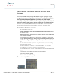
LFE-8139ATX/HTX LFE-8139ATX/HTX LFE-8139ATX/HTX LFE-8139ATX/HTX LFE-8139ATX/HTX LFE-8139ATX/HTX LFE-8139ATX/HTX LFE-8139ATX/HTX LFE-8139ATX/HTX LFE-8139ATX/HTX LFE-8139ATX/HTX LFE-8139ATX/HTX LFE-8139ATX/HTX LFE-8139ATX/HTX LFE-8139ATX/HTX LFE-8139ATX/HTX LFE-8139ATX/HTX LFE-8139ATX/HTX LFE-8139ATX/HTX LFE-8139ATX/HTX LFE-8139ATX/HTX Fast Ethernet Adapter Installation Guild Rev : LFE-8139 ATX/HTX Published : Aug. 1999 FCC Class B Statement This device complies with Part 15 of the FCC Rules. Operation is subject to the following two conditions: 1. This device may not cause harmful interference. 2. This device must accept any interference received, including interference that may cause undesired operation. Warning: This equipment has been tested and found to comply with the limits for a Class B digital device, pursuant to Part 15 of the FCC Rules. These limits are designed to provide reasonable protection. This equipment generates, uses and can radiate radio frequency energy and, if not installed and used in accordance with the instructions, may cause interference to radio communications. However, there is no guarantee that interference will not occur in a particular installation. If this equipment does cause harmful interference to radio or television reception, which can be determined by turning the equipment off and on, the user is encouraged to try to correct the interference by one or more of the following measures : n Reorient or relocate the receiving antenna. ii n Increase the separation between the equipment and receiver. n Connect the equipment into an outlet on a circuit different from that to n which the receiver is connected. Consult the dealer or an experienced radio/TV technician for help. Notice: Shielded interface cable must be used in order to comply with emission limits. Notice: Changes or modification not expressly approved by the party responsible for compliance could void the users authority to operate the equipment. CE Mark Statement The 10/100BASE-TX Fast Ethernet Adapter has passed the test performed according to EUROPEAN STANDARD EN 55022/A1 Class B, and EN 50 082-1:1997(EN 61 000-4-2:1995, EN 61 000-4-3:1996, EN 61 000-4-4:1995). iiii 1 Introduction Preface T hank you for purchasing our product! This guide is designed for the experienced network users. It contains information about installation and configuration of LFE8139ATX/HTX network interface card (NIC) a 32-bit high performance Fast Ethernet PCI Local Bus adapter. It can be easily implemented in any IBM PC/AT and compatibles with PCI local-bus master slot. LFE-8139ATX/HTX network interface card (NIC) provides a Remote Wake-Up connector, which can be connected to the PC motherboard through a wake-up signal cable, thus enabling the function of Remote Wake-Up. --11-- Introduction Our next versions of network adapter cards will fully support PCI 2.2 specifica tions to provide PMEB function of ACPI directly through the PCI slot. Thus, you will no longer need to use the wake-up signal cable. Instead, the adapter cards can directly support the Remote Wake-Up function through PMEB signal, saving users the trouble of connecting with a wake-up signal cable. LFE-8139ATX/HTX operates automatically at either 100Mbps or 10Mbps, depending on the speed of network device connected . Peripheral Component Interconnect (PCI) Bus Overview T he Peripheral Component Interconnect (PCI) local bus is a high performance, 32- or 64-bit bus that dramatically increases the speed of I/O-bound peripherals by directly connecting these devices to the CPU local bus. It is intended to be used as an interconnecting mechanism among highly integrated peripheral controller components, peripheral add-on cards, and processor/cache/memory subsystem. It is an industrystandard local bus architecture that provides end-users with high performance and ease of use without requiring high cost. --22-- Introduction PCI is CPU-independent, optimizes I/O functions and accommodates multiple high performance peripherals such as LAN, SCSI, and Graphics. It enables concurrent operation of the local bus with the processor/cache/memory subsystem. The following PCI block diagram shows a typical PCI local bus system architecture: --33-- Introduction The processor/cache/memory subsystem connects the PCI local bus through a PCI bridge. This bridge supports a low latency path through the processor, and may directly access PCI devices mapped anywhere in the memory or I/O address spaces. It also provides a high bandwidth path that allows PCI masters to directly access the main memory. The bridge may optionally include functions such as data buffering/posting and PCI central functions. PCI bus can provide the following features: t t t t Processor independent Multiplex, burst mode operation Synchronous at frequencies up to 40 MHz 120 Mbytes/sec usable throughput (132 Mbytes/sec maximum) for a 32-bit data path t Capable of full-concurrency with the processor/cache/memory subsystem t Full multi-master capability allowing any PCI master peer-to-peer access to any PCI slave t Comprehensive support for auto-configuration through a defined set of standard configuration --44-- Introduction Product Description LFE-8139ATX/HTX is a 32-bit PCI Fast Ethernet network interface card. It is designed for use on computers with PCI bus slots. LFE-8139ATX/HTX runs in bus master mode, directly sending/receiving Ethernet packets to/from memory. The bus master device is an intelligent device that can conduct processing independent of the bus or other devices. The bus master device coordinates the sharing of the bus between the main processor and target devices. Bus mastering allows a peripheral device to take control of the system bus instead of only relying on the central processor. LFE-8139ATX/HTX complies with the IEEE 802.3u, IEEE 802.3, IEEE802.3x Full Duplex Flow Control and PCI Local Bus version 2.2, and transmit data to the network at 10/100 Mbps. LFE-8139ATX/HTX can also operates in full-duplex mode to double the network speed up to 20/200Mbps when working with a Fast Switching hub. It is the fastest Ethernet design of its kind. LFE-8139ATX/HTX provides one RJ-45 port for connection with 10BASE-T Ethernet/100BASE-TX Fast Ethernet network, and automatically senses the connection type. --55-- Introduction LFE-8139ATX/HTX also supports ACPI (Advanced Configuration Power Management Interface) and PCI power management for advanced operating systems that are capable of OSPM (Operating System Directed Power Management) to achieve most efficient power management. The following figure shows the board layout of LFE-8139ATX/HTX network interface card: Figure : 1-1a The LFE-8139ATX Network Interface Card --66-- Introduction Fig. 1-1b LFE-8139HTX Network Interface Card --77-- Introduction Remote Wake-up Support L FE-8139ATX/HTX network interface card (NIC) provides a Remote Wake-Up feature that, when combined with other remote control functions, allows users to remotely wake up machines during off hours to perform maintenance activities through network. The system can be woken up from a sleeping state to a full-powered state over the network. Once the system is awake, it can be directed to run utilities and then return to sleeping mode again. If installed in a PC that supports Remote Wake-Up through the PCI bus, LFE8139ATX/HTX can still feed on an alternate power source even when system being in power-off state, thus making an all-time network monitoring. When in such a sleeping state, once a wake-up packet arrives, it will alert and wake the system up to a fullpowered state, ready to perform maintenance tasks or others. --88-- Introduction Auto-Negotiation Support NWay auto-negotiation enables LFE-8139ATX/HTX to automatically run at the speed and duplex mode that the connected hub supports. Auto-Negotiation detects the modes that are currently running on the device on the other end, and announces its own ability to automatically configure the highest performance mode possible for this connection. If supported on both ends of the connection, auto-negotiation process is initiated to negotiate for one of the following modes: l l l l Features 200 Mbps/FDX 100 Mbps/HDX 20 Mbps/FDX 10 Mbps/HDX t Support 32-bit PCI Local Bus master for high throughput and low processor utilization t Full comply with PCI Rev.2.2 and PC98/99 standard --99-- Introduction t Comply with the Ethernet/IEEE 802.3u 100BASE-TX and 10 BASE-T industry t t t t t t t t t t standard Support IEEE 802.3x Full Duplex Flow Control Comply to ACPI(Rev 1.0), PCI Power Management(Rev 1.1), and Device Class Power Management reference Specification(V 1.0a), such as to support OS Directed Power Management(OSPM) environment Allow remote wake-up (Magic Packet, LinkChg and Microsoft wake-up frame) Support auxiliary power-on internal reset, to be ready for remote wake-up when main power still remains off Support 4 Wake-On-LAN (WOL) signals (active high, active low, positive pulse, and negative pulse) Plug and Play: Simply insert the card into a PC and it will automatically be configured by the PC BIOS Support full-duplex operation to double the network speed up to 20Mbps (10BASET Ethernet) or 200Mbps (100BASE-TX Fast Ethernet) LED indicators to report network status Provide single RJ-45 connector with auto-sensing of 10 or 100Mpbs network operation Support PCI clock speed from 16.75 to 40 MHz, capable of zero wait state --1100-- Introduction t Support PCI VPD (Vital Product Data ) t Support optional Remote Boot ROM socket t (only for LFE-8139ATX) Support up to 128K bytes Boot ROM interface for both EPROM and Flash Memory (only for LFE-8139HTX) Support 1M Bytes Boot ROM on-board for Flash Memory t Extensive use of VLSI component that integrates Fast Ethernet MAC, Physical chip and transceiver in one chip to provide high hardware reliability, small power consumption and reduced network interface card size t Provide a comprehensive setup program to display network adapter configuration, including diagnostics on board or on network. What is ACPI Power Management? ACPI (Advanced Configuration and Power Interface) is a power management concept introduced by Intel, Toshiba and Microsoft in 1997. It is an open industry standard, which encompasses PC hardware, Operating System and peripheral device interface specifications. ACPI is a further step away from the previous time-based power management system, which often turns off peripherals at most inopportune moments without taking any potential needs into management considerations. --1111-- Introduction Conversely, ACPI is a demand-based power management endeavor. It allows for the collection of power consumption information from the entire system and gives complete control of device activity to the Operating System. Thus, ACPI enables the computer to provide power to only those devices that need it and at the time when they need it with the help of OS. Operating within a ACPI-enabled environment, LFE-8139ATX/ HTX Network Interface Card can take full advantage of its superior power management feature to perform Remote Wake-up function in Power Down mode. This will contribute, together with your ACPI-compatible OS (such as Windows 98 or Windows 2000) to a most economical PC power consumption. According to the definition of ACPI, there are four Global System States that are identified as the following 4 levels: G0: normal operating state G1: power-saving sleeping mode where the display and HD are shut down to save power consumption. A trigger event will recover the power-saving state to normal state. G2: Power Down mode with minimum power consumption. The minimum power is to offer the Wake-Up device such as LFE-8139ATX/HTX to activate and reboot the system from a cold start. The Wake-Up On LAN NIC such as --1122-- Introduction LFE-8139ATX/HTX works at this level. G3: The system is turned off by power switch. The power switch must be turned On to activate the system. While the system is in Power Down mode, LFE-8139ATX/HTX is still on the alert. Once a Magic Packet addressed to the client computer is received by its Wake-UP device such as LFE-8139ATX/HTX NIC, it will trigger a sequence of events to wake up the remote computer from sleeping state. While there might still be other legacy systems which are not compatible with ACPI, you might still preserve its original power saving feature if your system components allowing it. But we will see a gradual migration to all ACPI features in PC system. In order to fully benefit from the advantages of ACPI power management, not only your PC has to be ACPI-compatible but also your Operating System. However, an ACPI-compatible Operating System running on a non-ACPIcompatible system might not give any benefits from the OS-directed Power Management, since all power management will be restricted within BIOS. --1133-- Introduction The migration to ACPI power management is now accelerating to a full speed in the PC industry. Systems using ACPI are already on the market and we will see more in the near future. Since Microsofts Windows 98 and the future release of Windows 2000 will be fully ACPI-compatible and will incorporate OSPM (Operating System Directed Power Management), ACPI will become a dominant Power Management standard very soon. --1144-- Introduction Package Contents Before you proceed further, please check and see whether you have all the necessary accessories from the shipping package and make sure nothing is missing. The complete package should include : ¡· LFE-8139ATX/HTX Network Interface Card ¡·2 driver diskettes ¡· ¡·Remote Wake-Up cable ¡· ¡· This User Manual If any of these items is damaged or missing, please contact your authorized network supplier. --1155-- 2 Hardware Installation T his chapter will guide you through the installation of LFE-8139ATX/HTX on your computer. First, you must install the NIC on your system. After having properly installed LFE-8139ATX/HTX, you may connect the Remote Wake-up signal cable with connectors on the NIC and motherboard. Or you may install the optional Remote Boot ROM if needed (Only applicable to LFE-8139ATX). And finally, you must correctly connect and configure your network before the NIC can properly function within your network. Quick Installation Basically, the NIC installation involves the following steps: Step 1. Step 2. Insert Card into PCI slot. Connect to the Network. --1166-- Hardware Installation Step 3. Step 4. Connect the Remote Wake-Up signal cable (only necessary if you want to utilize Wake-On LAN function) Configure your Network (Cable Connection Examples.) The details of each step will be described in subsequent sections. Since LFE-8139ATX/HTX is a PCI-bus device, you will no longer need to configure this device after installation, because the system will automatically allocate resources such as I/O base address and IRQ at boot time. Simply follow the steps mentioned previously and leave the system to configure for you automatically. If you want to verify the basic functions of the NIC, you may run the diagnostic utility RSET8139. EXE on the LFE-8139ATX/HTX driver diskette. Step 1. Insert LFE- 8139ATX/HTX adapter card into the PCI mastering slot. Follow the steps below to install LFE-8139ATX/HTX on your system: 1. Turn off the computer and unplug the power cord from the power outlet. --1177-- Hardware Installation 2. Remove the computer cover. For information, please refer to your computer user manual. 3. Insert the NIC into an available PCI expansion slot. A PCI slot should be similar to one shown in Fig. 2-1. If you do not know how to identify a PCI slot on your system, please check your PC user manual or ask your system administrator. Make sure the NIC is inserted firmly in the PCI bus-mastering slot. 4. 5. 6. 7. Secure the NIC in the slot with a bracket screw. Replace the computer cover. If you want to insert another NIC into your system, repeat steps 1 - 5. Turn on the system power. --1188-- Hardware Installation Fig. 2-1 Insert the NIC into PCI slot (showing only LFE-8139ATX) --1199-- Hardware Installation Notes: l Make sure that the PCI machine does support master slots, INT multiple sharing and timing compatibility. Do not install LFE-8139ATX/HTX in a PCI slave slot. Please refer to your PCI system manual and select the appropriate configuration settings. l When installing multiple LFE-8139ATX/HTX adapters at one server, you should configure INT settings of the PCI slots correctly. Up to four LFE-8139ATX/ HTX adapters can be installed in a PCI file server running NetWare operating system. These four adapters share the same interrupt line with the driver supporting multiple INT services at the same time. Each LFE-8139ATX/HTXs IRQ should not conflict with that of the other adapters installed. l With the LAN driver, motherboard PCI slots are numbered beginning from 16, so the first PCI board is installed in slot 16 and the next one will be in slot 17. Slot number in some PC BIOS may be assigned to an initial number other than 16. l You must use EMM386 version 4.49 or higher, and install both DOS & EMM386 that came from the same DOS package to avoid possible software problems. --2200-- Hardware Installation Step 2. Connecting to the Network Y ou must connect the NIC to the network before installing the network driver. To connect the LFE-8139ATX/HTX NIC to the network cable, follow these steps: 1. Connect the network cable to the RJ-45 port on LFE-8139ATX/HTX NIC, as shown in Fig. 2-2 2. Connect the other end of the network cable to a 10BASE-T or a 100BASE-TX network port. 3. Check the LEDs, as shown in Fig. 3-1a, Fig. 3-1b. After installation of the network card, and you are now ready to install the network driver. But before you install the network driver, please take a few minutes to read the following LED status information: LFE-8139ATX l 10/100(M) LED ON (green) A good connection to 10BASE-T or 100BASETX port is established. l TX/RX (Activity) LED Blinking (green) The NIC is transmitting or receiving data from the network. --2211-- Hardware Installation l FUDUP (Full Duplex) LED ON (yellow) Run in Full Duplex mode. l PWR (Power) LED ON (green) The power of the NIC is receiving. Figure 2-2a Connecting the Network Cable to the RJ-45 Port (LFE-8139ATX) --2222-- Hardware Installation LFE-8139HTX l ACT/Link (Activity) LED Blinking (green) The NIC is transmitting or receiving data from the network. l FULL DUPLEX LED ON (yellow) Run in Full Duplex mode . Fig.2-2b Connecting the Network Cable to the RJ-45 Port (LFE-8139HTX) --2233-- Hardware Installation Please See Chapter 3 for more LED information. To connect the Remote Wake-Up cable, follow the next section Connecting the Remote Wake-Up to complete installation. Step 3. Connect the Remote Wake-Up signal cable W hen you install the NIC in a PCI bus-mastering slot in the PC, you can utilize the Remote Wake-Up feature of LFE-8139ATX/HTX NIC. You can skip this step if you have no intention to use the Wake-On LAN function. In order to perform Wake-On LAN function, you have to connect a Remote Wake-Up signal cable from a connector on the adapter to the wake-up circuitry on the motherboard. While plugging your wake-up signal cable into the three-pin connector, follow these steps below: 1. 2. Attach one end of the Remote Wake-Up signal cable into the connector on the NIC, as shown in Fig. 2-3. Each LFE-8139ATX/HTX NIC is accompanied with one Remote Wake-Up signal cable in the package. Attach the other end of the cable to the connector on the PC motherboard, as shown in Fig. 2-3. --2244-- Hardware Installation The location of connector on the motherboard will vary depending on the PC. 3. Reconnect all cables and replace the PC cover. the Remote Wake-Up function of LFE-8139ATX/HTX is enabled. Now you can install the network driver to work with your network operating system. Fig. 2-3 Connecting the NIC to the 3-pin connector --2255-- Hardware Installation Step 4. Configure your Network The NIC provides single RJ-45 port for connecting to 10BASE-T Ethernet/100BASE-TX Fast Ethernet network. The NIC will sense the type of connection automatically. For a detailed description of the connection type, please refer to the followings: Connecting to 100BASE-TX Fast Ethernet Network To connect the NIC to a 100BASE-TX Fast Ethernet network, you need a twisted-pair Category 5 or better cable with RJ-45 phone jacks at both ends. This cable allows a maximum length of 100 meters. Follow steps below to connect to Fast Ethernet network: 1. Plug one end of the cable into RJ-45 port of the NIC. 2. Plug the other end of the cable into a Ethernet/Fast Ethernet Switching hub (such as Ether-FSH8TX ) or a Fast Ethernet Standard Hub (such as Ether-FH16T / FH8T) --2266-- Hardware Installation Fig. 2-4 Connecting the NIC to the Switch --2277-- Hardware Installation Connecting to 10BASE-T Ethernet Network To connect the NIC to a 10BASE-T Ethernet network, you need a twisted-pair Category 3, 4 or 5 cable with RJ-45 phone jacks at both ends. This cable allows a maximum length of 100 meters. Follow steps below to connect to Ethernet network: 1. Plug one end of the cable into the RJ-45 port of the NIC. 2. Plug the other end of the cable into a 10BASE-T Ethernet hub.(such as Ether-H16+ ) --2288-- Hardware Installation Fig. 2- 5 Connecting the NIC to the 10BASE-T Ethernet hub --2299-- Hardware Installation Correct Network Cable (STP/UTP) Requirements l l l l l l 100 Mbps network must be shielded twisted-pair (STP) or Category 5 unshielded twistedpair cable. Do not use Category 3,4 cable for 100 Mbps network operation, it could cause data loss. Category 3 or 4 cable is good for 10Mbps network only. Category 5 cable is also good for 10Mbps operation. If all network uses UTP Category 5 cable, that you may have the versatility to operate the network at either 100Mbps or 10Mbps speed without recabling your network due to cable category grade. Two pairs of wiring are required Depending on building codes, different insulation materials may be required. Plenumrated or TEFLON-coated wiring may be required in some areas. The wire gauge should be between 18 and 26 AWG.(Most telephone installations use 24gauge wiring.) UTP wire should meet the following requirements : ¡C ¡CSolid copper ¡CNominal capacitance : less than 16 pF/ft ¡C ¡CNominal impedance : 100 Ohms ¡C ¡CNominal attenuation : less than 11.5db ¡C --3300-- Hardware Installation Automatic Selection of the Media Type W hile installing the driver, it will automatically select the media type based on the type of cable connected. If you change the cable type, you must reinstall the driver to auto-detect the cable type. If the driver cannot detect which cable is connected or whether a cable is connected, check your cabling or network driver installation settings (Ex. modify net.cfg file parameters force line speed = 10 Mbps or 100 Mbps). 10/100 Auto- Negotiation (NWay) L FE-8139ATX/HTX NIC automatically runs at the appropriate speed, depending on the hub or device to which it is connected. It does this using NWay, a feature that complies with the IEEE802.3 standard. It also works with any of other IEEE-compliant products (including 10BASE-T and 100BASE-TX equipment such as the LE-8029R NIC or 100BASE-TX hubs). --3311-- Hardware Installation Remote Boot ROM Installation B oot ROM enables computer to load its operating system from over the network, instead of from local hard disk. This enables installation of the NIC in diskless workstations. LFE-8139ATX NIC provide with a Boot ROM socket for installation of remote Boot ROM of various sizes according to your need. (While LFE-8139HTX comes already with 1 MB Flash ROM on board, and thus has no need for a Boot ROM socket.) To install a remote Boot ROM on LFE-8139ATX, follow the steps below: 1. Discharge any static electricity from your body by touching a grounded metal object. 2. Orient the Boot ROM so that its notch coincides with the notch on the socket. Make sure that the Boot ROM is properly oriented. A wrong orientation might damage the chip. 3. Align the pins on the Boot ROM with the socket on the NIC and press the chip straight down until it is firmly seated on the socket. Be careful not to bend any pins on the chip. 4. Reboot the system to use the Boot ROM function. --3322-- Hardware Installation Fig. 2- 6 Boot ROM type Remote Boot ROM socket for LFE-8139ATX Y ou do not need to configure the adapter to specify the Boot ROM settings (default setting is enabled). Once the PCI system detects the presence of a Boot ROM chip on the adapter during boot time, it will automatically set a working configuration. LFE-8139ATX supports 8K,16K,32K,64K, and 128K EPROMs for an upgradeable Boot ROM. --3333-- 3 LED Indicators LFE-8139ATX comes with four LED indicators on the back plane of the adapter. LFE-8139HTX comes with two LED indicators. LED indicators inform you about the network status as shown in the Fig. 3-1a and 3-1b. If you experience any problems with the adapter, first make sure that the appropriate driver is loaded, the proper cable is connected to the RJ-45 port of the adapter, and the hub complies with the adapter specifications, such as 10Mbps 10BASE-T or 100Mbps 100BASE-TX. Then check the LEDs again to make sure the connection is valid and working.. LED indicators of LFE-8139ATX t FUDUP(Full Duplex) Indicator This indicator turns ON to indicate Full-duplex mode; otherwise, it is OFF. --3344-- LED Indicators The NIC supports full duplex at 10BASE-T and 100BASE-TX. If the Switch hub supports the NWay feature and full duplex, the LFE-8139ATX NIC automatically runs in full duplex. t 10/100(Link) Indicator This indicator turn ON under two conditions: a good connection has been established with a fast link pulse is detected on the UTP port and the adapter is running the network driver. If there is a problem with the connection. Check the network cable for continuity and cuts. If that does not resolve the problem, try replacing the cable. t PWR Indicator This indicator light indicates the power of the adapter is receiving. t Tx/ Rx (Transmit /Receive) Indicator This indicator flashes to indicate there is network activity the adapter is transmission or reception data from the network. --3355-- LED Indicators Fig. 3-1a LED indicators and the connector for remote wake-up signal cable (LFE- 8139ATX) --3366-- LED Indicators Table 3-1a describes the LED indicators of LFH-8139ATX: Table 3-1a LEDs indicators of LFH-8139ATX --3377-- LED Indicators LED indicators of LFE-8139HTX t ACT/Link (Transmit /Activity) Indicator This indicator flashes to indicate there is network activity the adapter is transmitting or receiving data from the network. t FUDUP (Full Duplex) Indicator This indicator turns ON to indicate Full-duplex mode; otherwise, it is OFF. The NIC supports full duplex at 10BASE-T and 100BASE-TX. If the switch hub supports the NWay feature and full duplex, LFE-8139ATX/HTX NIC automatically runs in full duplex. --3388-- LED Indicators Fig. 3-1b LED indicators and the connector for remote wake-up signal cable (LFE-8139HTX) --3399-- LED Indicators Table 3-1b describes the LED indicators of LFH-8139HTX: Table 3-1b LEDs indicators of LFH-8139HTX --4400-- 4 Setup Program LFE-8139ATX/HTX NIC package includes 2 diskettes containing the setup program. The Setup program provides a way to verify the configuration and to isolate possible faults. The setup new configuration option allows you to change the configuration parameters for the NIC to fit specific environments in which the NIC is installed. The adapters I/O port address and interrupt request level (IRQ) are set by the Plugand-Play BIOS. Other default settings can be changed for these situations shown below. This program provides the following functions: t Display the current configuration of the adapter. t While setting up the NIC on the computer, users can also specify specific network parameters for a different computer. --4411-- Setup Program t Perform network diagnostic tests to verify basic functions of the adapter and its ability to communicate over the network with another adapter. t Help you check the power management function. Before running the Setup program, make sure that the adapter driver is not loaded; otherwise, unpredictable results may arise. Performing RSET8139.EXE Program T he setup program is designed to make sure that the NIC is installed correctly and functioning properly on your computer. After installing LFE-8139ATX/HTX NIC on your computer, you must first boot to DOS and then change to the directory where RSET8139.EXE program file resides. While executing RSET8139.EXE in DOS, it will search for the NIC on your system. The utility will then present you with a screen showing the configurations it found. If RSET8139.EXE program does not recognize the configuration of the NIC you have installed, please verify your hardware installation is correct. Start RSET8139.EXE program again. --4422-- Setup Program The Setup program can set up the on-board configuration and provides diagnostic tests. It provides specific tests on basic function, EEPROM data Access, loopback operation, and the ability to communicate over the network with another adapter. To access this program, insert the Driver Diskette 1 into the floppy disk drive and then type the following command at the DOS prompt: >A:\RSET8139.EXE [Enter] --4433-- Setup Program If the NIC is installed, the setup program main menu such as shown in the figure below will appear on the screen: followings describe the available options on the main menu, and execute these function tests as listed below: --4444-- Setup Program 1. View Current Configuration On the main menu, select the View Current Configuration option and press [Enter], a screen such as the following figure will appear: This screen inform you about the current configuration of LFE-8139ATX/HTX NIC on your system. --4455-- Setup Program 2. Set Up New Configuration Select the Set Up New Configuration option from the main menu, and press [Enter]. A screen as shown below will appear: The following table lists the option settings you can change. --4466-- Setup Program Option Settings (unless otherwise indicated, all features are common to both LFE-8139ATX and LFE-8139HTX) --4477-- Setup Program CAUTION: Before setting the NIC for full duplex, make sure the switch port is also set to full duplex. Before you activate the switching hub-to-server connection, make sure the switch port and adapter are configured for full duplex. l If the NIC is connected to a repeater, you should select Auto Detect or half duplex setting. l If the Lan Wake Signal of the motherboard activates in high pulse, the NIC Lan Wake Signal should be set in high status, If the Lan Wake Signal of the motherboard activates in low pulse, the NIC Lan Wake Signal should be set in low status l When the Wake On LAN is enabled, the NIC can power up a PC remotely from standby or suspend mode using a wake-up packet that is sent through the LAN --4488-- Setup Program 3. Run Diagnostics Select the Run Diagnostics option from the main menu, and press [Enter], the screen appears as shown below. Under the Run Diagnostics pull-down menu, select the item that you want to test and press [Enter]. --4499-- Setup Program The Run Diagnostics tests will perform several verifications on the basic functions of LFE-8139ATX/HTX NIC. These basic Diagnostic Tests include: n EEPROM Test : EEPROM data read/write test n Diagnostics On Board : basic function verification on board. n Diagnostics On Network : To run this test on network, you need another computer set up as a Responder to receive packets from the adapter being tested and echo them back to the adapter. Starting the test as follows: 1.From the Run Diagnostics pull-down menu, select the Run Diagnostics On Network, and press [Enter], the On-Network Diagnostics Menu appears. 2.Set up another computer as a Responder using the Set Up As Responder option from On-Network Diagnostic Menu. 3.Select the Set up As Initiator form the On-Network Diagnostics Menu and connecting to Responder station then press [Enter]. This option checks LFE-8139ATX/HTX for communication over the network with another NIC to receive and transmit network packets. --5500-- Setup Program Perform a diagnostic test first on the NIC basic functions before running a test on its connectivity. This ensures that the NIC basic functions are working properly. If the diagnostic test fails, the NIC may not necessarily be defective. Commonly, this may be caused by incorrect option settings that conflict with the settings of other boards or by improper installation. Follow the steps below to test the adapter further: 1. Check the NIC installation to make sure the card is seated correctly in the slot. 2. Check the length and rating of the cable connection. 3. Make sure the PCI slot where you installed the NIC is active. Computers allow PCI slots to be activated or deactivated. This is done through the CMOS utility on your system. Please refer to your computer documentation for information about activating PCI slots. 4. Replace the failed NIC with a working adapter and run the diagnostic test program. 5. Install the NIC in another functioning PCI computer and run the tests again. 6. Replace all other PCI adapters from the computer and run the tests again. If the tests pass, the other PCI adapters may be causing the problem. --5511-- Setup Program If you have installed the NIC correctly but you still experienced problem, check the software. If you run the diagnostic tests successfully, you rule out a hardware failure on the computer. If the NIC passes all the tests and there still appears a problem, look at the cabling, software or other issues that might affect functionality on the network. ¡½ Run Power Management Test Function From the Run Diagnostics menu pull-down menu select the Run Power Management Test, and press [Enter], the Run Power Management Test appears. --5522-- Setup Program LFE-8139ATX/HTX NIC can be awakened by a wake-up packet (Magic Packet) and Wake-Up frame sent by management software, or by connecting or disconnecting the TP cable, and the system can be notified via PMEB signal. With this method, no one has to be at the PC to turn it on. If the PC does not boot up when a wake-up packet (Magic Packet ) is sent, please check the following steps : l Verify that the Wake-On LAN setting is enabled. l Verify that the Remote Wake-Up signal cable is connected correctly to the NIC as well to the motherboard. Unplug and reinsert the cable if necessary. --5533-- 5 Driver Installation Installing Network Drivers You must install a network driver to allow the NIC to work with your network operating system. LFE-8139ATX/HTX adapter card provides various network drivers on the driver diskettes. The followings provide you with the installation procedures for different network drivers. For detailed information for the installation on each Network Operating System (NOS), please refer to the README (.TXT) file on driver diskette. --5544-- Driver Installation Driver Installation Examples Before you start to install the driver programs, please refer to each directory that contains a README file, which provides you with detailed installation instructions, or execute the HELP8139.EXE help file viewer in DOS. This viewer utility will present you with a screen showing the information about how to install the network driver needed for LFE-8139ATX/HTX NIC to work with your operating system. --5555-- Appendix A Adapter Specifications Standards: IEEE 802.3 10BASE-T for 10 Mbps Baseband CSMA/ CD local area network IEEE 802.3u 100BASE-TX for 100 Mbps Baseband CSMA/CD local area network IEEE 802.3x Full Duplex Flow Control Bus Type: 32-bit PCI Bus Master WakeOnLAN mode: Support Magic Packet, LinkChg and Microsoft Wakeup frame ACPI mode: Supports : PCI bus Power Management Interface Spec.(Rev 1.1). D0, D1, D2, D3hot, and D3cold, 5 different power states. --5566-- Adapter Specifications PMEB (including LWAKE) can be generated form D1, D2, D3hot, and D3cold. Magic Packet wakeup. LinkChg wakeup. Microsoft Wake Up frame. Transmission Speed: IEEE 802.3u Auto-Negotiation for automatic speed selection. 10 Mbps (ordinary Ethernet), 20 Mbps (full-duplex Ethernet), 100 Mbps (ordinary Fast Ethernet), 200 Mbps (full-duplex Fast Ethernet) LED Indicator: LFE-8139ATX FUDUP(Full-Duplex), Tx/Rx (Transmit/Receive) , 10/100(Mbps media selection) and PWR (Power) LFE-8139HTX FULL DUPLEX, ACT/Link --5577-- Adapter Specifications Boot ROM Size: LFE-8139ATX, with Boot ROM socket 8, 16, 32, 64 and 128Kbyte LFE-8139HTX 1 MB Flash ROM on board Operating Temperature: 32 ~ 131 °F 0 ~ 55 °C Storage Temperature: -4 ~ 176 °F -20 ~ 80 °C Humidity: 10 ~ 90% RH non-condensing Dimension (L x W): LFE-8139ATX 12.0 x 6.5 cm LFE-8139HTX 12.0 x 4.5 cm Operating Voltage: +5V± 5% @ 300mA maximum --5588-- Appendix B UTP Cable requirements and RJ-45 Connector Pin Assignments UTP Cable Straight-through twisted-pair cable is typically used to connect a hub to a server or workstation. With a straight-through connection, Pin 1 at the server is connected to Pin 1 at the hub. Pin 2 at the sever is connected to Pin 2 at the hub, and so on. Figure A-1 shows the locations of pins on a standard RJ-45 connector on a twisted-pair cable. Table a-1 shows the wirings in a straight-through twisted-pair cable. (Pins 4, 5,7 and 8 are not used) --5599-- Appendix RJ-45 Connector Pin Assignments Figure A-1 shows the RJ-45 connector pin assignments. Figure A-1 Plug Pin Locations --6600--