1
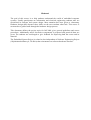
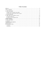
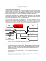
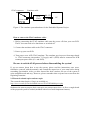
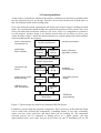
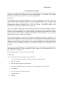
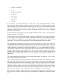
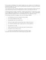
Embedded System Project (521423S)
Tero Vallius
Antti Tikanmäki
Juha Röning
Computer Engineering Laboratory
Department of Electrical and Information Engineering
University of Oulu
2008 fall
Abstract
The goal of this course is to help students understand the world of embedded computer
systems. Usually participants are information and electrical engineering students who are
specialized in software and system design. Most attention has been given to elementary
hardware design skills because these skills are the ones students often lack. This course is
structured as a guided walk through the hardware design process.
This document defines the project topic for fall 2008, gives general guidelines and course
procedures. Additionally major electronics components is proposed and practical hints are
given. The students are encouraged to give feedback for improving both the course and its
material.
The Embedded System Project is related to, but independent of Software Engineering Project
(Ohjelmistotekniikan työ, 521426A) that concentrates on software-hardware interface.
Table of contents
Abstract ...................................................................................................................................... 2
Table of contents ........................................................................................................................ 3
1. Course objectives ................................................................................................................... 4
2. Topic descriptions .................................................................................................................. 6
2.1 Basic topic: Portable Sensor Box ..................................................................................... 6
2.2 Research related topics and own topic ............................................................................. 8
3. General guidelines .................................................................................................................. 9
4. AVR JTAG-ICE Emulator system ....................................................................................... 10
4.1 System hardware ............................................................................................................ 10
4.2 Software development tools ........................................................................................... 11
5. Practical advice .................................................................................................................... 11
6. Main components ................................................................................................................. 12
7. Course procedures ................................................................................................................ 13
8. Summary .............................................................................................................................. 13
ACKNOWLEDGEMENTS ..................................................................................................... 13
APPENDIXES ......................................................................................................................... 14
Documentation Guide .............................................................................................................. 15
1. General ............................................................................................................................. 15
2. Structure ........................................................................................................................... 15
1. Course objectives
The purpose of the Embedded System Project (Sulautettujen järjestelmien työt) course is to
provide you knowledge and hands-on experience in the embedded computer system
technology. The course is intended to students specializing in software and system design,
giving most attention to hardware design, as understanding in this area is vital for most
embedded software designers. In short, this course is a chance for the very novices in
electronics design to create a simple embedded computer based device and to learn the
maximum from the experience.
You will learn both about design and tools. You will learn to study the components to fit the
various pieces together into a complete system and you will understand the role of a
microcontroller, seeing it as basic building block. In particular, you will concentrate on
hardware-software interaction, although very little software will be written in this project.
You will learn to design the schematics and layout using Printed Circuit Board (PCB) tools
(e.g. Eagle or Orcad), although their more advanced functions are not covered in this course.
In the end, you will learn to use an emulator and other microcontroller development tools
while testing the assembled circuit board you will make. Admittedly, there is a lot to be
learned.
The course is realized as a project-like assignment that requires approximately 120- 160 hours
from a team of three students during a single term. There are some topics to choose from. The
topics are divided to three categories: basic topic, research related topics and own topic. The
basic topic is meant for people that are new to the embedded systems. The basic topic
contains only familiar technologies and the teachers are familiar with the topic, enabling more
efficient tutoring. Also some suitable components for the assignment have been preexamined, letting the students to avoid the full exposure to “navigation” problems, such as
selecting, finding, and ordering components. The specification for this topic is already defined
and the basic structure of the work is fixed, but there are still some degrees of freedom in the
design.
The research related topics are meant for students with some experience in embedded
systems, and who can quite independently design the system. These topics are needed in the
current research in our University. They use modern technology and the design is predefined
only at high level. The students create the actual specification by themselves. This
specification is then checked and approved by the teachers. For these topics there are only a
few pre-examined key component proposals, but the students will choose most of the
components themselves. These topics give the students a great freedom of creativity. The
teachers will help with adjusting the specification to be not too difficult but still challenging
enough. The teachers will also help with the component selections and with the design, but
the students have the main responsibility of the design. As some of the components may be
new, they may prove to be non-functional in some designs. This is not a catastrophe and these
possibilities are taken into account in grading. However, careful planning and hard trying is
still required. The students may also propose their own topic. These proposals are handled
similarly to the optional topic specifications. Research related and own topics must not be
taken if the student does not have any experience on embedded systems.
We believe a reasonably painless completion of this course requires the following course
background: Digital Techniques I (Digitaalitekniikka I, 521413A), Computer Engineering I
(Tietokonetekniikka I, 521415A), and Computer Engineering II (Tietokonetekniikka II
521419A) and especially Embedded Systems (Sulautetut järjestelmät 521268A). In addition,
Software Engineering Project (Ohjelmistotekniikan työt, 521426A) and Principles of
Electronic Design (Elektroniikkasuunnittelun perusteet, 521431A) are useful.
We hope you will assist us in the development of this course by giving your criticism and
hints. The basic topic for fall 2008 is Portable Sensor Box.
2. Topic descriptions
2.1 Basic topic: Portable Sensor Box
The goal is to design a sensor box that is used to give diagnostic information from outdoor
robots, cars, motor cycles or other devices. The device measures the forces, acceleration and
vibration experienced by a device, the temperature of critical parts such as motor, brakes,
batteries or motor controllers, as well as existing ambient temperatures and humidity.
The device logs sensor values into an SD memory card for a long period of time. The logged
data can then be extracted to a computer via serial port. The sensors include a three axis
accelerometer, three temperature sensors and a humidity sensor.
The device works with a single 1.5 volt battery i.e. the current consumption must be
minimized and the operation voltage must be pumped up from the battery voltage. The device
contains also an LCD display and some buttons that are used to create a menu system. They
also enable reading current sensor values. The block diagram of the system is show below.
Figure 1. The main components of the portable Sensor Box
The basic requirements for the device are the following:
•
The serial interface works from MCU to PC. The unit sends all all logged sensor data
to the PC in a readable form. The data is read in PC with some regular ASCII based
terminal program such as Hyper Terminal. Data must be readable from SD card or
online from the sensors.
•
The serial interface works from PC to MCU. At least menu must be possible to be
controlled via PC.
•
Menu buttons can be used to operate the device. User must be able to start and stop
logging and data transfers from SD-card to PC via menu.
•
LCD display shows menu and some information, at least the current sensor values and
the amount of logged data.
•
The data is saved to an SD-Card.
•
The system stores also maximum and minimum values from sensors.
•
The device gets 3.3 volt operating voltage from a 1.5 volt battery.
•
The device utilizes power saving possibilities. MCU and all the components must be
in a power save mode or off when not used.
•
Device must measure acceleration, temperatures and humidity. At least one sensor
must be read via AD-converter (accelerometer), at least one sensor must be read via
i2c bus (temperature sensors).
These are also the basic grading points. Additional points can be received from additional
features that demonstrate utilizing different features of the MCU. You may include also
following optional features:
• PC data visualization for measurements
The device will be based on an Atmel ATmega series microcontroller (MCU). The students
are recommended to use ATmega32 controller. The control module is required to contain the
following on-board components:
•
•
•
•
•
•
ATMega MCU
some buttons for operating the device
LCD display
RS-232 interface for PC connection
JTAG connector for programming and testing the MCU
electronics needed to support required functions
More specific information about the device is available in course web page
http://www.ee.oulu.fi/research/tklab/courses/521423S/
The teams are free to create additional features to their system if they will. These additional
features affect positively (to a certain extend) to the grading of the team, provided that the
features are useful and working. All the basic features have to be met to pass the course.
The teams are free to choose any microcontroller environment for their system, but they are
strongly encouraged to use the Atmel ATmega32 microcontroller and the JTAG emulators
found from the student laboratory TS139. Before some other architecture is chosen the teams
shall consult with the supervisor of their team. For any other environment, the can not provide
the development tools.
The suggested emulator environment for developing the software and testing the implementations is presented in Figure 2. It consists of a PC and a AVR JTAG ICE Emulator.
The self-made PCB is connected to the JTAG connector.
JTAG connector
Emulator cable
Your own
AVR
JTAG
RS-232
PC
PCB
Figure 2. The emulator system hardware for the Embedded Systems Project.
How to connect the JTAG emulator cable:
1. Before connecting the JTAG emulator cable turn the power off from your own PCB.
The PC does not need to be shut down or switched off.
2. Connect the emulator cable to the JTAG connector.
3. Power up your own PCB.
4. Turn power on to AVR JTAG emulator. The emulator gets its power from target board
i.e. JTAG connector pins number 7 (Vsupply) and 2 (GND) must be connected to PCB
counterpart power lines (Vcc and GND).
Be sure to switch off all powers before disassembling the system!
If you are unsure about how to use the system, please read the instructions once more,
familiarize yourself with the manuals, and consult the supervisor of your team before doing
something questionable. After you have learned the basic routines, the use of the system is
quite straightforward and easy. However, please remember that everyone has to start from the
beginning sometime.
2.2 Research related topics and own topic
The research related topics (if any) are available at
http://www.ee.oulu.fi/research/tklab/courses/521423S/2008b/topics.php
Students who want to propose their own topic can contact supervisors. At first, a rough sketch
of the proposed system is needed (included with a list of most important features).
3. General guidelines
As this course is intended to students with software orientation, the question is probably about
the first electronics device you design. Therefore, do not rush, but proceed in good order, as
this will eliminate much of the learning pains.
First, write down the system requirements and sketch your design on paper avoiding too much
detail. The requirements should include the operational sequences of the system. Also write
down your ideas and calculations, and keep your notes, please. It is important for yourself to
see the progress, because design is an iterative process and you are likely to review your
earlier decisions. Figure 3 shows the major milestones in a typical small project that combines
software and hardware development.
power consumption,
environment etc.
partitioning,
basic solutions
System requirements
Sketch of
hardware
Sketch of
software
operation procedures
modes, functions,
algorithms, control
Evaluation and simulation
against requirements
schematics and
layout
Detailed
HW-design
Test
design
printed wiring board
manufacturing
PWB and
assembly
Software
continuity and
HW functionality
HW-tests
Simulator
tests
Integration
testability
considerations
embedded software
design
EEPROM
programming
Figure 3. Typical stages in a small-scale embedded HW/SW-project.
Familiarize yourself with the proposed components. This is necessary before detailed design
can be carried out. Selecting the components, or building blocks, is very time consuming,
unless you have prior experience and know what you are looking for. The component
selection process can be compared to finding pieces to a jigsaw puzzle: you may
approximately know your needs, but you do not know for sure if something you see fits
unless you try it.
In the course web pages we list a handful of key components. Please, remember that the list of
the components is just a suggestion and you can and need to use other components too.
First you are advised to check what components can be found from the store of the laboratory
TS102. More components can be found from component catalogues. The ordering of the
components is buffered, i.e. orders from a couple of groups are collected together before
sending it out. If you have selected some very special components you have to find out
yourselves the availability. Please, try to follow reasonable budget.
We recommend that in the beginning you should first study the functions of the components
and make sketches of their use. If you are still not sure how a component works, it’s a
good idea to build a test circuit. Tools for testing are available in the laboratory TS102.
The example applications presented on the data sheets are very helpful. After a few exercises
your data sheet reading skills have improved substantially. You will then start seeing
solutions and may proceed to the first sketch of the system. Alternatively, if you have some
prior experience, you may first make a rough sketch of the system and then look for suitable
components.
Keep in mind that in this system software works in a close interaction with hardware. Thus,
check every hardware change you make during design against the software functions and
system requirements. Check every wire of the components and the timing of every signal. The
first time it is laborious, but you will learn a lot in the process and will never regret it.
Use the PCB tools (Eagle or Orcad) after the design has stabilized. Try to learn the use of the
tools systematically, because this will speed up your work. It is good practice to exercise with
a simpler toy design. The final implementation and testing phases are quite rapid, when
compared to software design.
Finally, we recommend that you avoid dividing the tasks in the project between the members
of your team on a strict hardware/software basis.
4. AVR JTAG-ICE Emulator system
The Embedded System Project is suggested to be built using the one of the Atmel ATmega
series microcontroller, for which four AVR JTAG emulators can be found from TS139.
Emulators are connected to PCs and all the controlling and development software are run
under a Windows operating system. Detailed instructions of using the AVR JTAG, and the
software are found from the manuals, which every team is suggested to read (the manual is
available as a help documents in Atmel AVR Studio 4 software package, which is freely
downloadable at http://www.atmel.com). Short overview of the system and its general
structure is however presented in this section.
4.1 System hardware
The AVR JTAG-ICE is designed for developing software for Atmel ATmega series microcontrollers. The AVR JTAG-ICE is connected to PC via a serial cable and it uses the standard
JTAG interface to enable the user to do real time emulation of the MCU while it is running in
the target system.
The emulator supports hardware and software breakpoints, which are useful in debugging the
system. It also provides advanced capabilities for tracing the operation of the microcontroller,
as well the possibility to single-step the program currently performed by the system. During
the emulation IO register status is visible through AVR Studio. The limitation is that some
registers are not read since the reading changes the status of the register (e.g. USART data
register).
4.2 Software development tools
The tools for developing the software needed in the Embedded System Project consist of
these main software tools:
A) Compilers
• WinAVR is used for compiling and linking the software for the target microcontroller.
The WinAVR software is freely available.
B) IDE (Editing, downloading SW to MCU, running and debugging)
• Atmel AVR-studio 4 is used for writing the source code (other text editors can be used
as well), and for transferring the program code into the microcontroller, as well as
debugging and running the program. It includes also a C-level debugging tool and for
simulation of the program operation and a user’s manual for using the AVR JTAG. The
studio software is freely available.
All these software tools are installed into the two PC workstations connected to the emulators.
If the team wants to develop software at home, which is also recommend to some extend,
students can freely download all tools from Internet. Only the devices (JTAG-ICE, power and
oscilloscope) cannot be used at home.
5. Practical advice
Many of the following hints are based on the personal experiences of the authors and the
experiences from the last years courses. Most of them are warnings. To err is human and
destroying a component due to a design mistake is part of the life. See the latest advice from
the course web pages from address:
http://www.ee.oulu.fi/research/tklab/courses/521423S/2008b/help.php
• The workshop of the department has facilities for producing plated-through holes. The
printed wiring boards (PWBs) are made with a milling cutter (jyrsin), and the short
instructions can be found from course web page. Before milling the board show the
layout to your assistant. After that you can contact to Jari Pakarinen (tel. 553 2634, email
[email protected]) for milling the board.
• Make the power supply conductors wider than the signal wires. This is almost
impossible to correct later and regularly results in a new layout design round. A good rule
of thumb is that all the power conductors should be about 0.04” (1.0 mm), and the signal
conductors about 0.02” (0.5 mm).
• Place a capacitor close to the power supply pins of each integrated circuit. You may
have seen prototype boards that have extra capacitors added on the solder side.
• Never connect any output directly to the ground or power supply. This applies to the
testing stage, in particular, when one may be most tempted to give a signal by shortcircuiting.
• Many pins of the microcontroller can be programmed as either input or output. Incorrect
initialization as output may damage the circuitry, depending on the design. For this reason
the tests must be planned beforehand with care.
• With PCB tools it is deceptively easy to make apparent connections. The corrections force
you to go back to the schematics design stage and substantial modifications to the layout
may result. If you have already made the board, you may simply add a wire.
• After drawing a layout, print it as a 1:1 size print and try if the components fit on it. It is an
easy way to test if you have right footprints and enough space for each component.
• Pay special attention to the orientation and pin order of connector footprints when
drawing the layout and assembling the PCB. It is very easy to accidentally put the
connectors facing towards the center of the PCB or to the wrong side of the PCB.
• Don’t be afraid to put the components close to each other. It is better to have short leads in
order to avoid inductance disturbances. And small PCB:s look nicer. =)
• Always check the voltage and the polarity of the power supply before connecting it to your
design. Also use a +5V regulator (7805) in your design.
• Assemble your board step-by-step. First you should plug the voltages and check that every
voltage pin has the correct value. Also all plated-through holes should be checked.
• Do not connect any IC-chips before you have checked the voltages and connections of
every pin of its socket.
• If you get stuck, find help, if the situation persists for longer than a day. Try to find
solutions by working systematically.
• Above all, do not delay your start.
Please, notice that the device you design is a rather simple one and after this project you are
still relatively novice. More complex devices require substantially more attention to system
partitioning issues, buses, lengths of conductors on the PWB, etc.
Your feedback is always welcome.
6. Main components
Specific information about suitable components can be found from course web page
http://www.ee.oulu.fi/research/tklab/courses/521423S/2008b/components.php. There are also
suggestions for main components and some other documentation. However, your choices are
by no means limited to those components. Please, if you have any proposals to the list of
components let us know so that we can add the data sheets to the web page.
7. Course procedures
To ensure constant progress and completion of the projects the supervisor will have at least 5
scheduled 15-30 minute meetings with each team. During the meetings the teams will
describe their solutions, ideas and encountered problems, helping the supervisor to correct
serious design flaws at an early stage. The meetings also encourage to the planned use of
time, instead of painful around-the-clock marathons as the deadline approaches.
The contents of the meetings is as follows:
1: Inspection of initial (hand-drawn) design, calculations and preliminary
timetable. Advice on schematics and component list for students.
2: Inspection of the schematics, component order list, and the software plan.
Advice on layout for students.
3: Inspection of layout printed in 1:1 scale. Footprint check and permission for
milling the PCB.
4: Inspection of an assembled board. Advice on the emulator use for students.
5: Demonstration of working board. Report and board left for grading.
Experience from other project courses indicate that the initial design should be presented in 12 weeks after the start. Otherwise many students are tempted to delay their full commitment,
resulting in large delays in completion. In addition, the students have commented that ‘low
intensity’ projects result in much more working hours than necessary.
The results of each project team will be judged based on the demonstration, documentation,
implementation and the time used. The recommended report format is presented in Appendix
A. Notice, that without proper and sufficient documentation it is difficult to evaluate the
merits of any work.
We recommend that this course is taken only when the team has the intention and
dedication to complete the assignment during the fall semester.
Any proposals for improvements are gratefully accepted.
8. Summary
This course is a chance for the software oriented students to gain hands-on experience from
embedded computer system hardware design. Therefore, it is structured as a walk-through the
common design and implementation problems, while working on an application system.
ACKNOWLEDGEMENTS
Persons that have been developing this course and its material are Ari Pitkänen, Hannu
Rautio, Eric Galloix, Janne Haverinen, Tuukka Turunen, Lasse Jyrkinen and Olli Silven.
Their work is gratefully acknowledged.
APPENDIXES
Appendix A: Documentation guide
APPENDIX A
Documentation Guide
This guide is a shortened English version of the documentation instructions written for the
Electronics Design and Construction Exercise (Elektroniikan työ, 521441S). The original
Finnish version of this guide has been written by Seppo Nissilä.
1. General
The importance of the good documentation can never be emphasized too much. In the long
term research and development projects the correct documentation is vital. The report you
write to this course teaches you the necessary skills to write project reports. The
documentation structure explained here is also very similar to the thesis format of the
Department of Electrical and Information Engineering.
The report should be written by using a suitable wordprocessor. The schematics should be
printed out from the PCB tool. In other drawings you must follow the standard symbols
presented in the SFS handbook #10 (SFS:n käsikirja #10) and the SFS standard for the binary
logic symbols SFS 4612 (SFS:n standardi binäärilogiikan elimet SFS 4612). It is very likely
that these books can be found only in Finnish.
The document should be targeted to the audience having prior technical education. You
should avoid long and unnecessary descriptions of the terms that are already familiar to your
audience. The purpose of your report is that a reader having some technical education,
without any prior knowledge of the problem, can easily understands the research problem, the
background of the work, different alternative solutions, the solution selected and the results of
the work.
Please, try to keep the language of your documentation clear. Avoid using too long sentences
and meaningless words. It is also a good idea to give a quick view to the structure of one or
two master’s or doctoral thesis.
Documentation can be written in Finnish or English.
2. Structure
The documentation should include the following parts:
•
cover sheet (please remember to add your social security number!)
•
table of contents
•
abstract (in the language of the report)
•
abstract in English (if previous abstract in other language than in English)
•
introduction
•
technical options for implementation
•
implementation
•
testing
•
schedule and budget
•
results
•
further development
•
conclusion
•
bibliography
•
appendixes
•
feedback
In the abstract you should introduce the goal of the work, the implementation, and the
obtained results. The language should be as perfect as possible. The abstract cannot contain
any knowledge which is not presented in the body of the report. You are not allowed to make
references to any part of the other text, any equation, any figure, any table or any other
reference material. If the report is not written in English, you need to have also an English
translation of the abstract.
In the introduction you should present the background and purpose of your work, and give the
general idea what it is all about.
In the technical options for implementation section you should introduce the theories required
for your project (for example pulse width modulation, Manchester coding, IR-modulation),
present different possibilities for their implementation, and compare them. Based on the
comparison, you can justify your selections for the implementation in the next chapter.
The implementation should describe the tools (compiler, emulator and other tools), materials
(components and other materials and their purpose), methods used in you project, as well as
explain the details of your implementation (for example how you actually implemented pulse
width modulation or Manchester coding, IR-modulation, etc). The implementation should be
explained by dividing the solution to the logical blocks (and sub blocks if necessary). Start the
description from the most abstract logical level. The main focus of this chapter is in functional
solutions (more hardware than software), but you must also present a general description of
software you have implemented in this work. The program code should be included in the
appendixes.
The testing should describe the test cases and testing equipment and methods, as well as the
results of the tests and their analysis.
The schedule and budget should present the original time table plan and realized time table,
and some explanation of reasons for delays or anti-delays in the time table. Budget part
should calculate all the expenses concerning the project. It should contain the list of purchased
components with their prices, list of other components with approximated prices (consult the
catalogs) and some estimate of the work time and the salary estimate for that time. In other
words, you should estimate, how much the creation of this prototype would have cost, if you
had done it in a company. If you cannot find a cost for something, you may estimate it.
Based on all the previous chapters and your results you should analyze how well the goals of
the project were reached. If the goals did not get fulfilled, you should try to find the reasons
for it.
In the further development You should consider how the solution can be enhanced or
optimized, and how you would choose the implementation methods now that you have gained
the result from this prototype.
The conclusion presents a summary and the final results of this document. In this section you
are not allowed to present any new information or to refer to any other part of the text.
Normally appendices includes: schematics, component placing layout, component list, layout
of the PWB and the datasheets for the special components. Also a list of implemented
software should be included. In the text you should refer to every appendix you have.
The final page should be the feedback, where you can estimate whether
•
you think the topic was easy enough or way too hard,
•
you learned something in this course,
•
you think this course was useful to you,
•
the given credits matches the spent hours (please elaborate this part),
•
the estimated workloads in the assignment where correctly balanced,
•
the equipment were OK,
•
broken equipment slowed you down more than we warned you for,
•
assistants were any of help to you,
•
your interest in embedded systems increased or died for good
If you have ideas of how this course could be improved, please tell us.