1
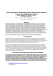
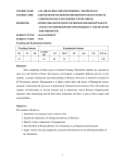
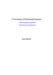
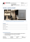
XVI IMEKO World Congress
Measurement - Supports Science - Improves Technology - Protects Environment ... and Provides Employment - Now and in the Future
Vienna, AUSTRIA, 2000, September 25-28
VIRTUAL INSTRUMENT AS AC MEASUREMENT TRAINING TOOL
1
M. Numminen1 and O. Aumala2
Tampere Polytechnic, Tampere, Finland
Tampere University of Technology, Tampere, Finland
2
Abstract: Software can be used to help students to learn the use and properties of
common electrical measurement devices. Virtual instruments are applied here to
realize a self-study package. Alternating current measurements can be trained with a
virtual signal generator and different types of virtual multimeters. The paper presents
educational needs clarified by study diaries as well as the virtual instruments
developed.
Keywords: Virtual instrument, Digital multimeter, AC measurement
1
INTRODUCTION
The properties and the using methods of common electrical measurement devices are unknown for
first year students in technical universities and polytechnics. Therefore the first exercises in
measurement laboratory are often troublesome. Most of the time is wasted on studying the equipment
and because of that the objectives of the laboratory exercises may not be reached.
The principle of laboratory exercises is 'to learn by doing' so that the students receive feedback
from their operations. This principle is difficult to realize with lectures in classrooms. Also the working
time in laboratory may have to be restricted because of the limitations of the laboratory resources. For
example, the number of measurement devices or the teaching personnel can be small at the same
time when the number of students attending to the laboratory exercises is large.
A self-study software can help students to learn some specific properties of measurement devices.
Using virtual instruments the students can study the properties of devices independently with their own
PC's. There are instrument emulators that can be downloaded from Web sites free of charge [1], or
the emulators can be used directly on the Web pages [2]. Also virtual instruments are developed for
lecture presentations [3]. Our idea is to offer the simulation software directly at the students' disposal.
Virtual instruments are programmed using a graphical software development environment. That is
a way to create most realistic instrument simulators.
2
EDUCATIONAL NEEDS
Most of the students use multimeters, oscilloscopes and function generators for the first time in the
laboratory exercises of the first year studies. That is one of the known problems in the laboratory
works. To find out more specific understanding of the learning process in the laboratory work it was
decided to make an analysis among the students who are participating in the course “Measurement
Technology” in Tampere University of Technology.
2.1
Learning process appraisement principles
One method to appraise the learning process is called portfolio. That is defined as a students own
portfolio, a collection of study works, which represents the students skills flexibly and appropriately.
The portfolio is selected by the student himself from works of some study period. The portfolio
includes the description of a study context, representation of the best works and the grounds of those
selections. The portfolio includes also the final appraisement, where the student describes his/her
study process, how it succeeded, the strong sides of his/her know how, the general progress, and the
future study plans [4]. The significance of the portfolio for a student is a process which deepens the
learning and self-knowledge. For a teacher the portfolio is an appraisement tool and a development
tool for education framework.
There is not only one correct form of the portfolio. It's character and contents can be changed
depending on the purpose [5]. The idea of portfolio is modified here to a study diary in which the study
process is documented during the laboratory exercises.
2.2
Study diaries
The research on the need for developing the education was performed as a study diary analysis.
From about 400 students participating the course, 35 students were chosen randomly to the learning
XVI IMEKO World Congress
Measurement - Supports Science - Improves Technology - Protects Environment ... and Provides Employment - Now and in the Future
Vienna, AUSTRIA, 2000, September 25-28
analysis group. Everyone of them wrote a study diary from each of the three laboratory exercises.
Study diaries had to be written during the laboratory work or just after the work, so that the diary would
contain real experiences. The form and contents of a study diary was not exactly defined.
Some advise for the content of the diaries was still given. The diary should answer for example the
following questions.
• What were the subject and the method of the exercise?
• How did you perform the exercise?
• What were the problems you met, and what were the solution alternatives?
• How did you solve the problems?
• What did you learn about this experience?
• What did you think when you solved the exercise?
• How would you appraise your achievement by yourself?
• How would you improve your execution?
2.3
Summary of the learning experiences
The course “Measurement Technology” includes three laboratory exercises [6]. The subjects of
those exercises are
1. Analog and digital multimeters
2. Oscilloscopes
3. Temperature measurements.
In the study diaries all of the three exercises were treated. However, only the experiences covering
the first exercise are presented in this paper. This is because the self-study software presented here is
planned to prepare the students to handle multimeters in the first exercise.
The following list shows the most often mentioned subjects in the study diaries concerning the first
exercise. The subjects were considered either as problems or as learning experiences.
• Use of multimeter and signal generator
• Determining the uncertainty of the multimeter
• Root mean square calculation for the sine and triangle waves
• Differences between the basic digital multimeter and the True RMS meter
• Concepts of the input and output impedance
• Compensation of resistances of the measurement wires
These subjects helped teachers to concentrate to solve the most frequent problems. One solution
to the problems is better training before the laboratory exercises. A self-study software is one possible
method to give students deeper understanding with some of the subjects mentioned above.
3
VIRTUAL INSTRUMENTATION
A self-study software has been developed to help students to learn the properties of measurement
devices. This software simulates a signal generator and different types of digital multimeters. Using
these virtual instruments the students can study the use and properties of those devices
independently with their own PC's.
Signal generator and digital multimeter simulators are accomplished using a software development
environment LabVIEW™ of National Instruments. Each LabVIEW instrument has two parts: the front
panel and the block diagram [7].
The front panels of signal generator and digital multimeter are analogous to front panels of real
instruments. The front panels consist of controls and indicators such as knobs, switches, buttons,
graphs and displays.
The block diagrams define the functions of instruments in a graphical programming language. For
the end user the block diagrams are hidden. Only the front panels are presented and given for
operations.
Typically a data acquisition board is installed in the PC to measure real-world physical signals.
However, in the training system all signals are created by the virtual signal generator and no data
acquisition board is needed.
Each one of the virtual instruments is showed on the screen in its own window, because they are
separate devices in the real world too. The data transfer between windows is accomplished using the
global variables [8].
Executable programs can be created with LabVIEW by using the LabVIEW Application Builder.
These executable programs can be distributed without the LabVIEW development software [9]. That is
especially important when the simulation software is distributed to the students. When the students
install the simulation software on their own PC's, the free of charge LabVIEW Run-Time Engine will be
XVI IMEKO World Congress
Measurement - Supports Science - Improves Technology - Protects Environment ... and Provides Employment - Now and in the Future
Vienna, AUSTRIA, 2000, September 25-28
installed at the same time. The student doesn't need any other software for the simulation
applications.
4
AC MEASUREMENTS
The simulator software contains two types of multimeters: a common multimeter and a True RMS
meter. The displayed root mean square value is calculated with different principles in those
instruments. Students can compare the displays of both types of meters with different signal types.
4.1
Digital multimeter
In a basic digital multimeter the AC measurements are based on the rectified mean [10]:
T
1
x m = ∫ x ( t ) dt
T0
where x(t) is the measured signal and T is the period of the signal.
(1)
Typically the users of digital multimeters are interested in the root mean square value [10]
T
x eff =
1 2
x ( t ) dt
T ∫0
(2)
For a sinusoidal voltage the rectified mean is
um =
2
⋅A
π
(3)
and the root mean square is
u eff =
1
⋅A
2
(4)
where A is amplitude.
The root mean square value in the multimeter's display is calculated from the rectified mean [10]
u eff =
π
2 2
⋅ u m = 1,11⋅ u m
(5)
This equation is valid only for sinusoidal signals with zero mean, or for signals which have the form
factor 1,11. If the signal has an offset, or if the waveform is different from sinusoidal, an incorrect value
is displayed.
4.2
True RMS meter
The displayed value of a True RMS meter is generated using equation (2). The True RMS meter
thus measures the root mean square of all waveforms correctly.
4.3
Virtual multimeters
The displays of the simulation program are presented in the figures 1 and 2. The layouts of the
displays are similar. In the upper window there is a signal generator where frequency, amplitude,
offset and waveform can be changed during the simulation.
The alternating voltage from the signal generator is measured by three instruments shown in the
lower part of the display. The first window is the waveform monitor like an oscilloscope without user
definable settings. The second instrument is the basic digital multimeter where the root mean square
value is based on the rectified mean. The third instrument is the True RMS meter which displays the
correct root mean square value for all types of waveforms.
Two typical cases when the basic digital multimeter gives an erroneous result are shown in the
above mentioned figures. Figure 1 shows a triangle wave measurement and figure 2 the measurement
of a sine wave with an offset.
XVI IMEKO World Congress
Measurement - Supports Science - Improves Technology - Protects Environment ... and Provides Employment - Now and in the Future
Vienna, AUSTRIA, 2000, September 25-28
Figure 1. Triangle wave measured using a basic digital multimeter and a True RMS meter.
Figure 2. Sine wave with offset measured using a basic digital multimeter and a True RMS meter.
5
EDUCATIONAL OBJECTIVES
The main principle underlying laboratory exercises is that students learn effectively through doing
practical tasks. The principle of ’learning by doing‘ needs two qualifications. Firstly, the tasks have to
XVI IMEKO World Congress
Measurement - Supports Science - Improves Technology - Protects Environment ... and Provides Employment - Now and in the Future
Vienna, AUSTRIA, 2000, September 25-28
be perceived as relevant and meaningful by the students. Secondly, students have to receive
constructive feedback on their performance [11].
The presented simulation software is primarily intended for pre-laboratory training. The students
can learn independently the use and properties of laboratory measurement devices. The front panels
of signal generator and digital multimeters are made essentially similar to those devices used in
laboratory. Consequently, if the student is able to operate the virtual instruments, he or she can do the
same with real devices.
The virtual instruments of the simulation program are running real-time. When a student turns the
amplitude knob of the virtual signal generator, the effect can be seen immediately on the display of the
virtual multimeter. The student gets an immediate feedback from his operations.
The signal generator and multimeter simulators presented in this paper are the first steps of an
extensive process of the education framework development. Still more instruments can be simulated
with software. Also the functions can be improved to correspond to those of real instruments.
REFERENCES
[1] Agilent Educator's Corner, Lab Equipment. http://www.educatorscorner.com/labequipmnt
/equipmnt.html. 9. December 1999.
[2] Ch. Schmid, A Remote Laboratory Using Virtual Reality on the Web, Simulation 73 (1) (1999) p.
13-21.
[3] L. Referowski, R. Roskosz, D. Swisulski, Progress in Lecturing of Electrical Measurements Using
Virtual Instruments, in: Proc. IMEKO XIV, Tampere, Finland, 1997.
[4] P. Linnakylä, P. Pollari, S. Takala, Portfolio as support to appraisement and learning (Portfolio
arvioinnin ja oppimisen tukena) University of Jyväskylä, 1994. (in Finnish).
[5] P. Linnakylä, P. Pollari, S. Takala, The several possibilities of a portfolio (Portfolion monet
mahdollisuudet) University of Jyväskylä, 1996. (in Finnish).
[6] Laboratory exercises in the course 75116 Measurement Technology, Tampere University of
Technology, 1997 and 1998, (in Finnish).
[7] LabVIEW User Manual, National Instruments, Austin, Texas 1998.
[8] G Programming Reference Manual, National Instruments, Austin, Texas 1998.
[9] LabVIEW Application Builder, Version 5.1 Release Notes, National Instruments, 1999. 17 p.
[10] O. Aumala, Fundamentals in Measurement Technology (Mittaustekniikan perusteet), 8. edition,
Otatieto, Helsinki 1999, 223 p. (in Finnish).
[11] G. Brown, M. Atkins, Effective Teaching in Higher Education, Routledge, London, 1990, p.94.
AUTHORS: Mikko NUMMINEN, Tampere Polytechnic, Department of Electrical Engineering, P.O.Box
21, 33521 Tampere, Finland, Phone Int. +358 3 264 7358, Mobile Phone Int. +358 50 301 0359, Fax
Int +358 3 264 7311, E-mail: [email protected] and
Olli AUMALA, Tampere University of Technology, Department of Measurement and Information
Technology. P.O.Box 692, 33101 Tampere, Finland, Phone Int. +358 3 365 2483, Fax Int. +358 3 365
2171, E-mail: [email protected]