1
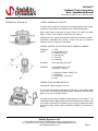
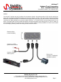
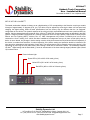
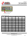
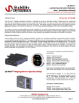
LG Alert™
Oshkosh Truck Corporation
User / Installation Manual
Document No. 800017 Ver. 04 (March 2007)
US Pat. No. 6,130,608
INTRODUCTION
The LG Alert™ Lateral Acceleration Indicator is intended for use as an early alert system to assist drivers in recognizing
when they are exceeding set maximum maneuvering limits of the vehicle. The device monitors and displays lateral g-forces
perpendicular to the vehicle direction and travel in real time. The lateral sensitivity of the device can be adjusted using the
digital push buttons on the front of the base unit. “00” is the least sensitive setting and “99” is the most sensitive setting.
An auxiliary horn jack provides additional signals indicating the full scale of the device has been exceeded, in addition to
signal output jacks providing voltages biased at +2.5 VDC proportional to applied g-forces for data logging or trip recording
applications. Internal filtering reduces the effects of high frequency accelerations associated with bumps and vibration.
OPERATING PRINCIPLE
The foundation of the LG Alert™ Lateral Acceleration Indicator is a complete acceleration measurement system contained
in a hermetically sealed monolithic IC. The signal conditioning circuitry incorporates a force balance control loop and bias
adjustment to center the signal about zero. This provides a bi-polar voltage proportional to the applied g-force. The value of
the lateral signal is determined and output to the display module, with lateral g-force to either the left or right of the vehicle
displayed as an increasing level from left to right on the display. Internal temperature regulation of sensitive IC’s virtually
eliminates error associated with changes in surrounding temperature. The device can be set to display a full-scale lateral
acceleration range between 0.17 and 1 g-force.
Part Number 900034 includes the following
components.
400011
400004
400009
700001
700002
800017
800002
Display Assembly
Base Assembly
Mounting Bracket Assembly
Display Cable Assembly (10 ft.)
Power Cable Assembly (10 ft.)
User / Installation Manual
Remote Horn Assembly
LG AlertTM Helping Drivers Operate Safely
Note: The LG Alert™ requires 12 ± 3 VDC input
for standard operation. If the power available is
out of the 12 VDC range, an optional power
supply is available that will accommodate a 9 to
36 VDC input providing a 12 VDC output to the
LG Alert.
OPTIONAL POWER SUPPLY
400008 Power Supply
700003 Power Supply Input Cable (10ft)
700006 Power Supply Output Cable (10ft)
Stability Dynamics Ltd.
10 Trent Drive, P.O. Box 670, Campbellford, Ontario, Canada, K0L 1L0
Ph: (705) 653-0775 Fax: (705) 653-4732 Email: [email protected]
www.stabilitydynamics.com
Page 1
LG Alert™
Oshkosh Truck Corporation
User / Installation Manual
Document No. 800017 Ver. 04 (March 2007)
THEORETICAL PRINCIPLES
LATERAL FORCES ON A VEHICLE
Turning a corner results in a momentum force perpendicular to the vehicle
center line. This is known as a lateral g-force or lateral acceleration.
When these lateral forces become large enough, the vehicle will either
slide or overturn. This condition is referred to as a “rollover”.
Lateral forces on a vehicle can be determined by the summation of radial
acceleration associated with turning a corner and the tilt component
related to the force of gravity on the vehicle.
LATERAL g FORCE CALCULATION WHEN TURNING A CORNER
FORMULA:
Values:
a = V2/R
a = acceleration (m/s2)
R = radius of turn (m)
V = velocity (m/s)
F = force (N)
m = mass (kg)
Constants:
Force of gravity = 9.81 m/s2
EXAMPLE:
Turning Radius (R) = 50m
Velocity (V) = 40 km/h
a = (40km/hr x 1000m / 3600s)2 / 50
a = 2.469 m/s2
g = (2.469 m/s2) / (9.81 m/s2)
g = 0.25
FORCES ON AN INCLINED SURFACE
Acceleration = SIN (tilt angle) x 9.81 m/s2
The LG Alert™ displays the total lateral acceleration on the vehicle, which
is the sum of the turning acceleration and the component associated with
gravity. (E.g. from an inclined surface)
A tilt table can be used to establish a safe setting for the LG Alert™. The
relationship between digital setting and full-scale sensitivity is shown in the
set up table. Alternatively, the device can be set by an experienced driver
and tested under actual vehicle operating conditions to determine a
setting.
Stability Dynamics Ltd.
10 Trent Drive, P.O. Box 670, Campbellford, Ontario, Canada, K0L 1L0
Ph: (705) 653-0775 Fax: (705) 653-4732 Email: [email protected]
www.stabilitydynamics.com
Page 2
LG Alert™
Oshkosh Truck Corporation
User / Installation Manual
Document No. 800017 Ver. 04 (March 2007)
INSTALLATION
LOCATION
Both base and display modules should be located within the driver compartment.
Oshkosh Truck Corp. has pre - selected a mounting location on the Striker ARFF vehicle dashboard, and installation
drawings for the vehicle should be followed.
The base module should be positioned as low in the cab as possible using the10 ft. cable provided. It must be firmly
attached to the vehicle framework close to the front axle, and as close to level as possible. Access to the base unit’s front
and rear panels should not be obstructed to allow access in case of “sensitivity” setting adjustment. The front and rear
panels of the base unit must be aligned with the vehicle forward direction of travel. Cables should be located away from
contact by people and equipment and secured to reduce fatigue due to vibration.
ATTENTION: ORIENTATION OF LG-ALERTTM IN THE CAB OF THE VEHICLE IS CRITICAL TO THE PROPER
OPERATION OF THE DEVICE. ENSURE THAT THE DEVICE IS INSTALLED AS PER INSTRUCTIONS AND DIAGRAM
BELOW.
Selector Switch
Must be in the UP position
(as supplied from the factory).
Do not change position.
Front of device must
be facing driver
Front View (Cover Removed)
LOCATIONS TO AVOID
The display module is designed to fit exactly into the dash mounting location specified by the Oshkosh Truck Corp. in the
Striker ARFF vehicle.
The base module must be protected from transient conditions and impact.
Do not locate the device in an area that may be exposed to the weather.
Do not locate in areas of high humidity or temperature extremes (E.g. engine compartment)
Do not locate in areas exposed to turbulent air from fans, doors or windows
Do not locate in areas exposed to high electromagnetic interference
Do not locate in areas that may allow impact from people or equipment
Do not route cables through areas of high electrical magnetic interference.
Stability Dynamics Ltd.
10 Trent Drive, P.O. Box 670, Campbellford, Ontario, Canada, K0L 1L0
Ph: (705) 653-0775 Fax: (705) 653-4732 Email: [email protected]
www.stabilitydynamics.com
Page 3
LG Alert™
Oshkosh Truck Corporation
User / Installation Manual
Document No. 800017 Ver. 04 (March 2007)
DIMENSIONS
DISPLAY UNIT
BASE UNIT
Stability Dynamics Ltd.
10 Trent Drive, P.O. Box 670, Campbellford, Ontario, Canada, K0L 1L0
Ph: (705) 653-0775 Fax: (705) 653-4732 Email: [email protected]
www.stabilitydynamics.com
Page 4
LG Alert™
Oshkosh Truck Corporation
User / Installation Manual
Document No. 800017 Ver. 04 (March 2007)
WIRING
The LG-Alert™ requires only two (2) cables to be connected to function. One cable provides 12 VDC from the vehicle fuse
panel, and is connected to the Base Assembly rear connector, labeled “ 12 VDC “. The second cable connects the Display
Assembly to the Base Assembly. It is connected on one end to the Display Assembly rear connector, and the other end
connects to the Base Assembly rear connector, labeled “DISPLAY”. An internal fast blow fuse provides protection for the
device. The power lights on both the Base and Display units should illuminate upon powering the unit. There is a warm up
period of approximately 120 seconds where the device may display imbalance. During installation, the device can be tested
for functionality by attaching cables and rotating the base module as shown.
Rotate as shown
to test functionality
Connect to +12VDC
ignition switched source
Connect to negative
chassis ground
Remote Horn
Connects to “HORN/SIG”
(installation optional)
Stability Dynamics Ltd.
10 Trent Drive, P.O. Box 670, Campbellford, Ontario, Canada, K0L 1L0
Ph: (705) 653-0775 Fax: (705) 653-4732 Email: [email protected]
www.stabilitydynamics.com
Page 5
LG Alert™
Oshkosh Truck Corporation
User / Installation Manual
Document No. 800017 Ver. 04 (March 2007)
TROUBLE SHOOTING
NO POWER
Check fuse and power connections
Base and Display units should have all power lights illuminated
If the lights are not illuminated, the device may malfunction.
Check the supply voltage to the device. Voltages less than 9 VDC or greater than 15 VDC are outside the device
specification range and may cause false readings. Abnormal supply voltage fluctuations caused by faulty equipment or
loose wires may cause the highly sensitive amplifier circuits to give a false reading, or appear unbalanced.
For voltage ranges of 9 to 36 VDC, an optional power supply is available. See information on Page 1.
UNBALANCED OPERATION
The device may have shifted during service or the characteristics of the vehicle may change over time causing the device to
be out of balance. This error can be removed by zeroing the device. This is accomplished using the adjustment screw on
the lower front panel of the base unit, after removing the front cover. If the left and right balance of the device cannot be
corrected with the zero adjust, the device may require servicing.
ZEROING THE DEVICE
The device can be zeroed using a tiny 1/16” flat screwdriver to turn the zero adjust screw found inside the front panel of the
base module. The cover must be removed to obtain access to the zero adjustment screw. Make sure the vehicle is on a
level surface before starting. Count the rotations of the zero adjustment screw between one indicator light on the display for
left and right lateral accelerations. For example, turn the zero adjustment screw until only one green light is illuminated on
the display module. Count the number of turns required to pass through zero, turning off the first light and continue to turn
the screw until the same light is illuminated. Simply divide the number of turns by two and rotate adjustment pot to the
middle point, which should be close to zero. A setting of ‘99’ on the ‘sensitivity’ adjust digital push button will provide the
maximum gain to easily visualize the error. Make sure the device is re-set back to its original digital push button
setting after zeroing.
Power Indicator Light
Zero Adjust Screw
Self Test Pushbutton
Front View (Cover Removed)
Stability Dynamics Ltd.
10 Trent Drive, P.O. Box 670, Campbellford, Ontario, Canada, K0L 1L0
Ph: (705) 653-0775 Fax: (705) 653-4732 Email: [email protected]
www.stabilitydynamics.com
Page 6
LG Alert™
Oshkosh Truck Corporation
User / Installation Manual
Document No. 800017 Ver. 04 (March 2007)
SET UP OF THE LG-ALERT™
The lateral acceleration indicator is factory set at a digital setting of ‘55’ corresponding to the first alert occurring at a static
tilt angle of approximately 15 degrees (0.26 ‘g’s). The device may be adjusted by removing the base unit front panel and
changing the digital setting. Static tilt table specifications from the factory may be different than the “as equipped”
configuration of the vehicle. The dynamic response of the vehicle is highly unpredictable and can have a profound effect on
stability. Vehicle characteristics and response of the LG-Alert™ define the recommended setting as described in the NRC
report to Transport Canada “Development of a Training Program for Drivers of High Capacity, High Center of Gravity Airport
Rescue and Fire Fighting (ARFF) Vehicles, Dec 10, 1998”. Management may choose a sensitivity that is even more
conservative. Once a setting for a vehicle has been established, management must put in place a clear policy that the
device is never altered. Any change in device setting must be clearly documented and all personnel informed especially if
the device is rendered less sensitive. A routine inspection of the device setting and operation should be included in the
short test drive undertaken at the beginning of each shift. The self-test button can be pressed to ensure the device is fully
operational by removing the front panel screw, and inserting a small wire to activate the switch. The relationship between
LG-AlertTM digital setting and the associated ‘g’ forces to activate each of the three warning stages (indicator lights 8,9 and
10) is shown below.
Power Indicator Light
Green LED’s (10% to 60% of full-scale g force)
Yellow LED’s (70% to 80% of full-scale g force)
Red LED’s (90% to 100% of full-scale g force)
Stability Dynamics Ltd.
10 Trent Drive, P.O. Box 670, Campbellford, Ontario, Canada, K0L 1L0
Ph: (705) 653-0775 Fax: (705) 653-4732 Email: [email protected]
www.stabilitydynamics.com
Page 7
LG Alert™
Oshkosh Truck Corporation
User / Installation Manual
Document No. 800017 Ver. 04 (March 2007)
Digital Sensitivity Adjustment
00 to 99 (Refer to chart)
Front View (Cover Removed)
LG-ALERT™ SENSITIVITY TABLE
Lateral Tilt Angle
Digital
indicator light 8
indicator light 9
Push Button
is on at (deg)
is on at (deg)
Setting 00-99
99
95
90
85
80
75
70
65
60
55
50
45
40
35
30
25
20
15
10
8.0
8.5
9.1
9.8
10.5
11.3
12.2
13.1
14.2
15.3
16.5
17.7
19.1
20.6
21.7
24.0
25.9
30.5
36.0
9.1
9.6
10.3
11.1
11.9
12.8
13.7
14.8
15.9
17.1
18.4
19.8
21.3
22.9
24.7
26.5
30.1
35.3
42.0
Lateral Acceleration
indicator light 10
is on at (deg)
indicator light
8 “g” forces
indicator light 9
“g” forces
indicator light
10 “g” forces
10.0
10.6
11.4
12.3
13.2
14.3
15.4
16.6
17.9
19.4
20.9
22.6
24.4
26.4
28.5
30.8
33.3
39.0
48.0
0.14
0.15
0.16
0.17
0.18
0.20
0.21
0.23
0.24
0.26
0.28
0.30
0.33
0.35
0.37
0.41
0.44
0.51
0.59
0.16
0.17
0.18
0.19
0.21
0.22
0.24
0.25
0.27
0.29
0.32
0.34
0.36
0.39
0.42
0.45
0.50
0.58
0.67
0.17
0.18
0.20
0.21
0.23
0.25
0.27
0.29
0.31
0.33
0.36
0.38
0.41
0.44
0.48
0.51
0.55
0.63
0.74
Stability Dynamics Ltd.
10 Trent Drive, P.O. Box 670, Campbellford, Ontario, Canada, K0L 1L0
Ph: (705) 653-0775 Fax: (705) 653-4732 Email: [email protected]
www.stabilitydynamics.com
Page 8
LG Alert™
Oshkosh Truck Corporation
User / Installation Manual
Document No. 800017 Ver. 04 (March 2007)
LIMITATIONS OF LG ALERT
This device is intended as an early alert system to assist drivers in recognizing when they are approaching maneuvering
limits that are potentially unstable. While this device can provide invaluable information to the operator of the vehicle, it
must be recognized that the LG Alert™ has limitations.
The device will not prevent the vehicle from overturning
The device can not work without a suitable, steady power source (there are no batteries)
The device may not work properly if the power supply drops below 9 VDC or rises above 15 VDC
The device must be properly installed. The base module must be level when the vehicle is loaded and on level
ground. Any error in the device orientation will appear as an error on the display module.
The device will not provide proper readings if the orientation is altered through physical impact or abuse. Ensure a
routine inspection is followed to check for functionality and device orientation.
The audio alarm will not function if disabled
The device may function improperly if the cable between the base and display modules is lengthened or altered.
Consult Stability Dynamics Ltd. regarding cable length limitations
The device may malfunction if the cable between the base and display modules is routed through an area of high
electromagnetic interference (i.e.: through engine compartment). A specialty shielded cable may be required if
electromagnetic interference disrupts signal reliability.
The device power supply must be between 9 and 15 VDC. Extraneous noise or high voltages from the vehicle
alternator may cause internal damage to the device. If this is a concern, a power-conditioning unit should be installed
between the device and the vehicle battery circuit to filter out noise.
The LG Alert™ is not a substitute for property, disability, life or any other insurance of any kind. Appropriate insurance
coverage is your responsibility. Consult your insurance agent. The LG Alert™ Lateral Acceleration Indicator is NOT to be
relied on, wholly or in part as a substitute for proper driver training, vehicle operation and continued instruction respecting
the safe operating parameters within that a vehicle must be operated.
Stability Dynamics Ltd.
10 Trent Drive, P.O. Box 670, Campbellford, Ontario, Canada, K0L 1L0
Ph: (705) 653-0775 Fax: (705) 653-4732 Email: [email protected]
www.stabilitydynamics.com
Page 9
LG Alert™
Oshkosh Truck Corporation
User / Installation Manual
Document No. 800017 Ver. 04 (March 2007)
LIMITED WARRANTY
Stability Dynamics Ltd. warrants the LG Alert™ Lateral Acceleration Indicator to be free from defects in materials and
workmanship under normal use and service conditions for a period of one year from date of purchase. This warranty is in
lieu of any other warranty either expressed or implied. No manufacturer, agent, representative, dealer or employee of the
company has the authority to modify or alter the obligations or limitations of this warranty. This warranty is limited to the
repair or replacement of the LG Alert™ Lateral Acceleration Indicator. This warranty does not cover damage resulting from
negligent handling, painting, disassembly, misuse or lack of reasonable care. In no case shall Stability Dynamics Ltd.’s
liability under any other remedy prescribed by law exceed purchase price of the LG Alert™ Lateral Acceleration Indicator.
Your LG Alert Lateral Acceleration Indicator is not a substitute for property, disability, life or any other insurance of any kind.
Appropriate insurance coverage is your responsibility. Consult your insurance agent.
The duration of this warranty, including that of merchantability of fitness for any particular purpose, shall be limited to the
period of one (1) year from the date of purchase. Stability Dynamics Ltd., the manufacturers and their respective officers,
directors, agents and employees, or any or all of them shall have no liability for any personal injury, property damage or any
consequential or incidental damage for breach of this or any other warranty, expressed or implied whatsoever, even if the
loss or damage is caused by the Company’s negligence or fault. Some jurisdictions do not allow exclusion or limitation of
incidental or consequential damages so the above limitation or exclusion may not apply to you. This warranty gives you
specific legal rights and you may also have other rights that may vary from province to province.
For repair within the warranty period, return this product postage prepaid along with proof of purchase date to Stability
Dynamics Ltd. Please enclose a note stating the nature of the difficulty. In the event that you have any questions
concerning the use, care and/or service of this product, please write, fax or email to the following address;
Stability Dynamics Ltd.
10 Trent Drive, P.O. Box 670
Campbellford, Ontario, K0L 1L0, Canada
Ph: (705) 653-0775 Fax: (705) 653-4732 Email: [email protected]
Web: www.stabilitydynamics.com
Stability Dynamics Ltd.
10 Trent Drive, P.O. Box 670, Campbellford, Ontario, Canada, K0L 1L0
Ph: (705) 653-0775 Fax: (705) 653-4732 Email: [email protected]
www.stabilitydynamics.com
Page 10
LG Alert™
Oshkosh Truck Corporation
User / Installation Manual
Document No. 800017 Ver. 04 (March 2007)
NOTES:
Stability Dynamics Ltd.
10 Trent Drive, P.O. Box 670, Campbellford, Ontario, Canada, K0L 1L0
Ph: (705) 653-0775 Fax: (705) 653-4732 Email: [email protected]
www.stabilitydynamics.com
Page 11
LG Alert™
Oshkosh Truck Corporation
User / Installation Manual
Document No. 800017 Ver. 04 (March 2007)
NOTES:
Stability Dynamics Ltd.
10 Trent Drive, P.O. Box 670, Campbellford, Ontario, Canada, K0L 1L0
Ph: (705) 653-0775 Fax: (705) 653-4732 Email: [email protected]
www.stabilitydynamics.com
Page 12